BastelBaus
-
Extra Gadget: the little sister
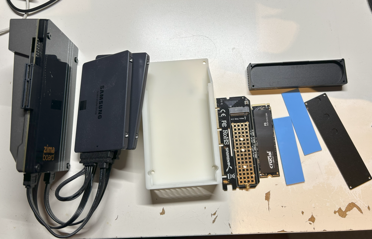
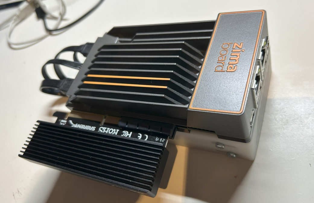
12/20/2023 at 21:02 • 0 commentsSince my overall plan was to create a multi-site private cloud and backup system, I needed a second option for the other side. Also here zero noise was mandatory so I decided to go with a passive ZimbaBoard setup
Here the components and th e full assembly which was quite straight forward with teh 3D printed SDD mount.
Component Selection ~costs(12/23) Main-PC ZimbaBoard 832 w/ dual SSD cable ~200€ Storage Main SSD: Crucial P3 500GB M.2 PCIe Gen3 NVMe
PCIe2SSD adapter: Sabrent M.2 SSD NVMe PCIe Adapter
Storage SSD: 2x Samsung 870 QVO 4TB35€
15€
360€Housing from thingiverse, ordered at JLCPCB <10€ Total: 620€ -
Finising the build
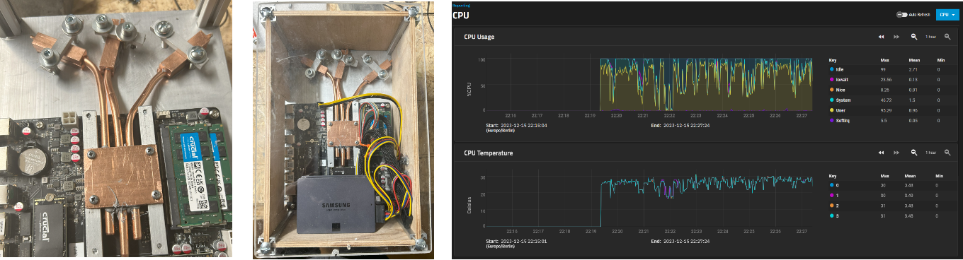
12/20/2023 at 20:44 • 0 commentsFinally I closed the housing and .. the NAS booted successfully (I was a bit affraid of damageing the bare die CPU when mounting the cooler). The temperatures stay below 40° with full load and the maximum I reached was belwo 50° with full CPU load for >6hours.
So overall not the cheapest build but I am quite happy with the sice, the zero noise and the good performance!
-
Mounting it all together
12/20/2023 at 20:38 • 0 commentsThen it was time to add thermal past again, and mount the copper block by pressing it with the alluminium bars to the CPU. I re-used the springs of teh original cooler block. I am quite happy with this design, since I could mount the CPU cooler and then start to mount the heat pipes. This was not as comfortable in my passive PC build.
Then after experimenting with the position of the heat pipe connections to the alluminium cooler, I drilled threaded holes to mount the copper blocks to the cooler. To bend the pipes I re-used the 3D printed bending tool I used already for the passive PC build. Then I added thermal paste and fixed the heat pipes at the cooler block.
Final step was to mount the other ends of the heat pipes to the alluminium cooler by pressing them with small alluminim bars onto it. -
Building the cooling block
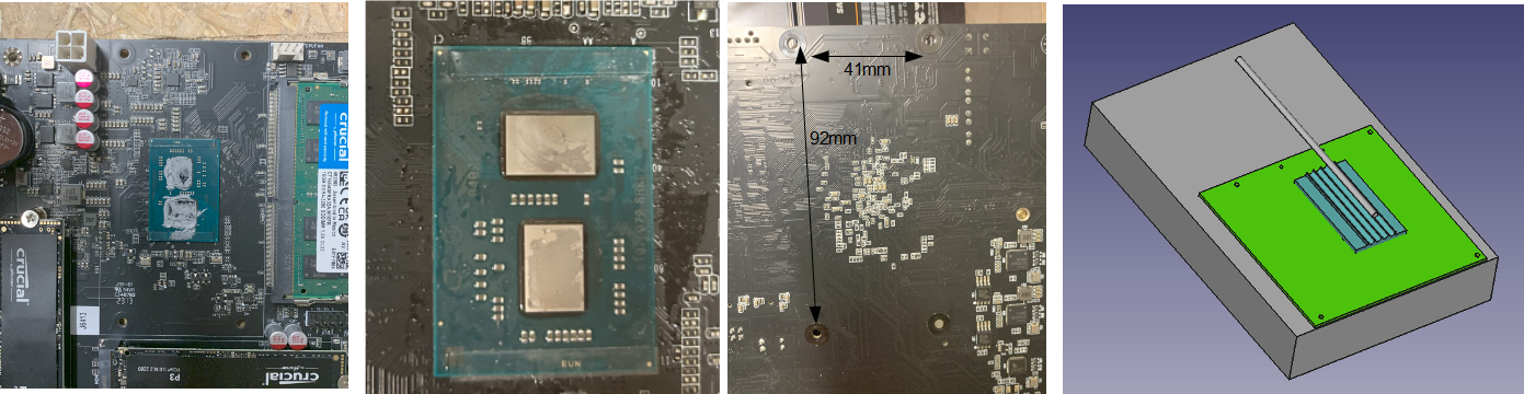
12/20/2023 at 20:15 • 0 commentsI did not find any dimenions of the mainboard cooler mounting holes in the internet so I was wuite interessted how they axactly look like. So the next step was to dismantle the default cooler and removing the thermal paste. I did a small sketch how I planned to mount he cooper block to the bare die CPU and connect the heat pipes to the alluminium cooler.
all
My initial plan was to mill the upper and lower copper blocks at ones with my quite simple 18x30 CNC but this significantly failed this time (it worked not to bad for my passive PC build). Also the initially planmned 4 pipes had been to close together to cope with my mechanical skills so I had to reduce to three (which is still sufficient as I found out with the final build).
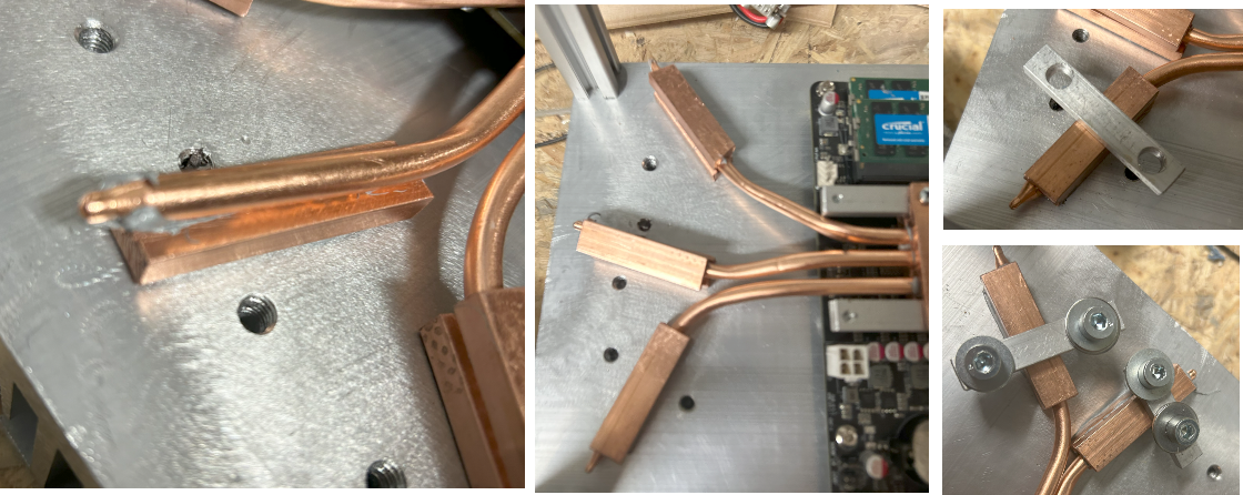
Since I had only milled about 1 or 2 mills when I gave up my initial plan, I used the same copper blockes, drilled holes (and threads) and mounted them together. Then with a good 6mm drill bit I drilled 3 holes. From my past experiences I knew that it was important to fix the copper blocks quite tightly together before drilling a hole in the interface of both.
Then it was quite some manual effort to create space for the alluminium mounting brackets by first filing and finally using a metal saw.
I drilled holes and threads in the alluminium mounting brackets and sanded the copper bottom to be mounted to the bare die CPU chips.
Finally I cut 6 copper bars, clammed them very tightly together and drilled three holes into them. And yes, I did not take care enough to drill the hole very straight but this should not harm the function.
-
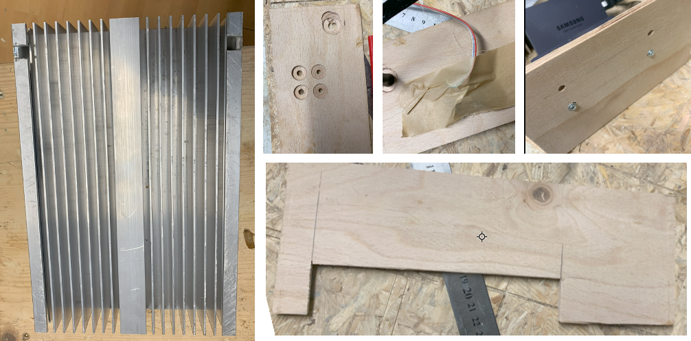
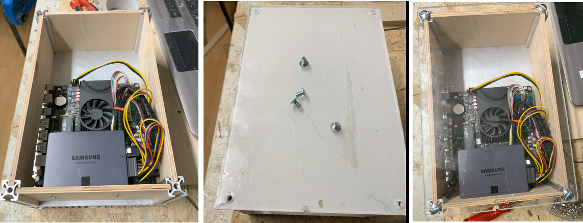
Assembly of the electronics and building the base housing
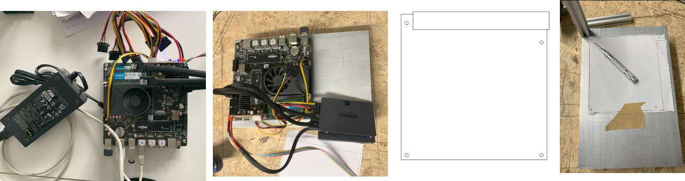
12/20/2023 at 19:41 • 0 commentsOf course the first thing what to do when new PC components arrive is to build them together (picture left, only with boot SSD) and check if it is running. And yes, it was running :-). Next I took the cooler andcopied the micro-itx holes to the alluminium cooler with a printed schematic.
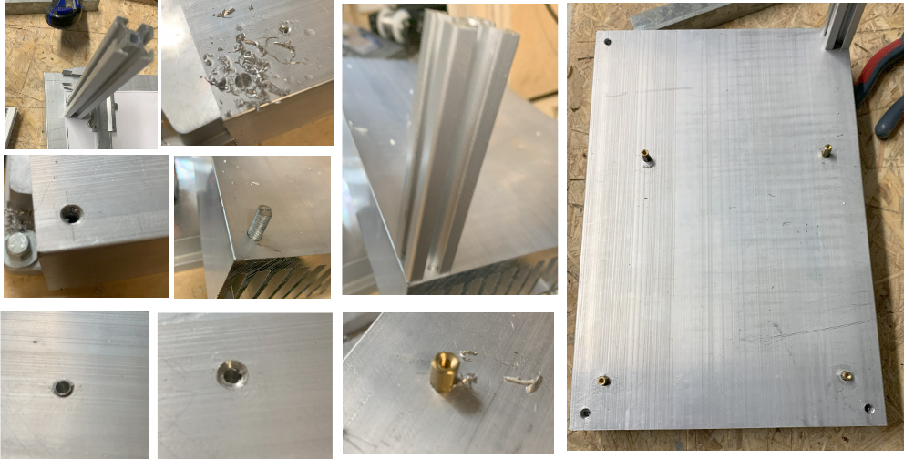
As corners I used 20x20mm Bosch profiles with 10cm length with M6 threads. For mainboard I mounted on small 3mm distance bolts.
To mount the housing on the wall, I just cutted to holes in the alluminium cooler. For the sides I used 6mm thick scrap wood which fits perfectly between the profiles. For the power connection, the LEDs and the on/off button I drilled small holes in the side and fixed them by hot glue.
Putting everything together it looked already quite satisfying and as lid I used a 6mm acrylic sheet I had laying around which I screwed onto the profiles.
Zero noise DIY NAS (bro & little sis)
DIY full passive NAS with 2x4TB SSDs, 3x2.5GbE and 32GB RAM. Full hardware build for multi location cloud setup.
 So overall not the cheapest build but I am quite happy with the sice, the zero noise and the good performance!
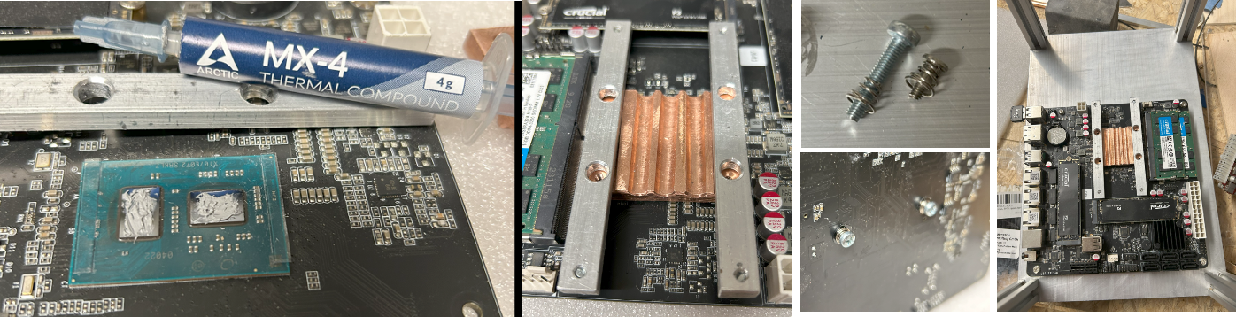 Then after experimenting with the position of the heat pipe connections to the alluminium cooler, I drilled threaded holes to mount the copper blocks to the cooler. To bend the pipes I re-used the
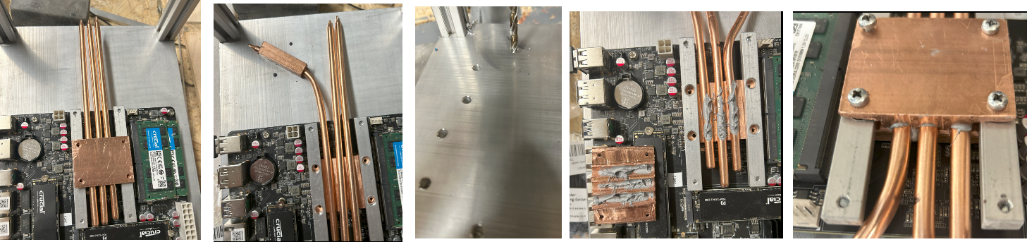
 My initial plan was to mill the upper and lower copper blocks at ones with my quite simple 18x30 CNC but this significantly failed this time (it worked not to bad for my
 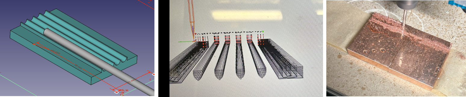 Since I had only milled about 1 or 2 mills when I gave up my initial plan, I used the same copper blockes, drilled holes (and threads) and mounted them together. Then with a good 6mm drill bit I drilled 3 holes. From my past experiences I knew that it was important to fix the copper blocks quite tightly together before drilling a hole in the interface of both.
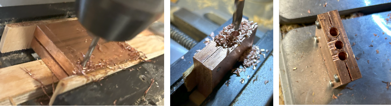 Then it was quite some manual effort to create space for the alluminium mounting brackets by first filing and finally using a metal saw.
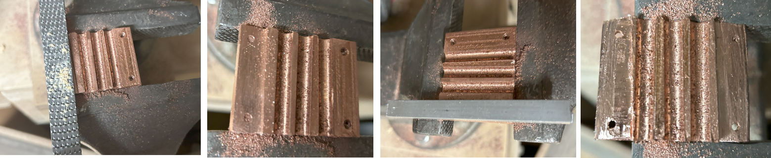 I drilled holes and threads in the alluminium mounting brackets and sanded the copper bottom to be mounted to the bare die CPU chips.
 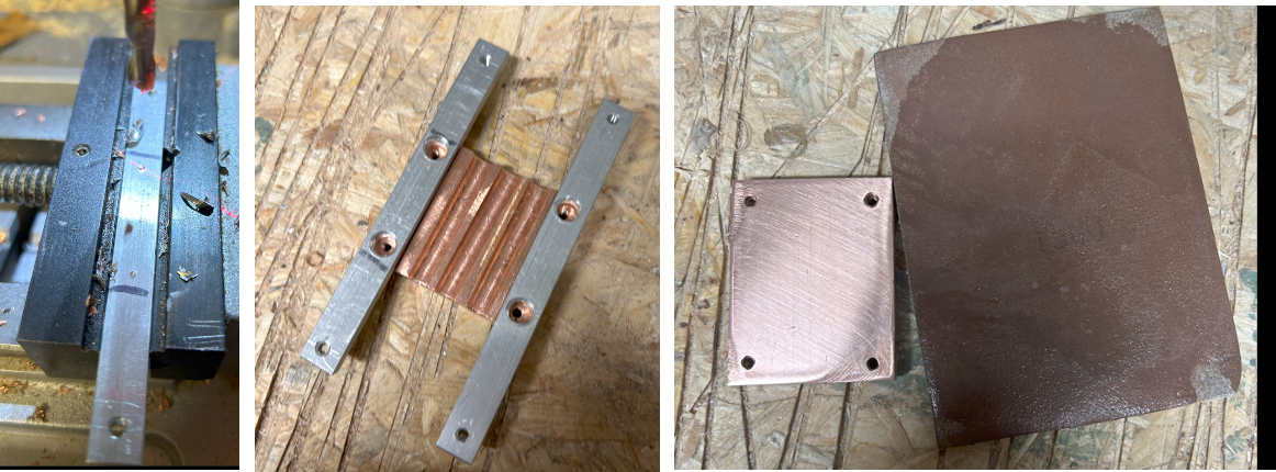 Finally I cut 6 copper bars, clammed them very tightly together and drilled three holes into them. And yes, I did not take care enough to drill the hole very straight but this should not harm the function.
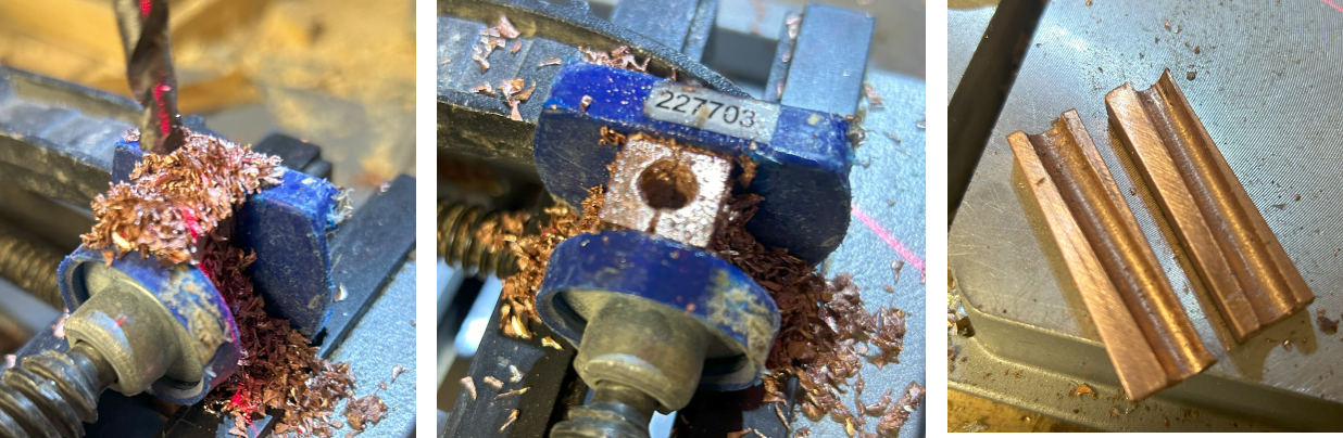
 To mount the housing on the wall, I just cutted to holes in the alluminium cooler. For the sides I used 6mm thick scrap wood which fits perfectly between the profiles. For the power connection, the LEDs and the on/off button I drilled small holes in the side and fixed them by hot glue.