agp.cooper
-
I am Back
03/15/2017 at 13:04 • 0 commentsI am Back
I have been on holidays and busy working on a couple of other projects.
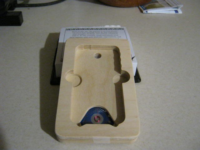
Anyway I fired up the CNC and made three more wooden slices for the modem case.
Just one more wooden slice and the strip-board to go.
I have to have a look at the strip-board layout and how I am going to route the USB cable.
Also some code to communicate to the host computer and to set the modem as originate or answer.
The other problem is that I will need to make a second modem to talk to!
The Modem Box
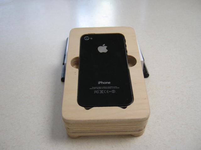
Here is the completed modem box (top view):
![]()
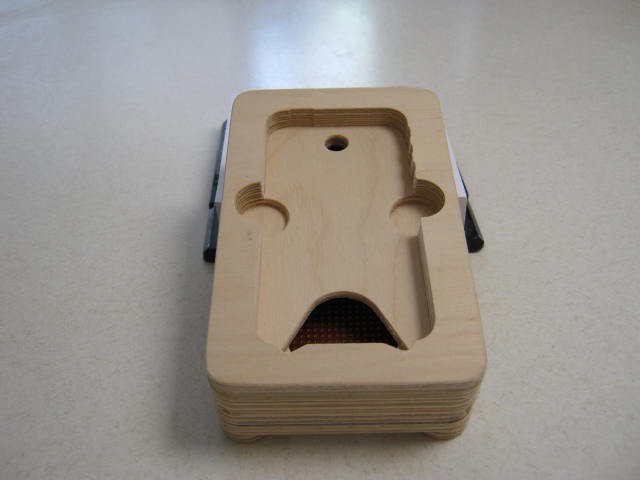
No iPhone:
![]()
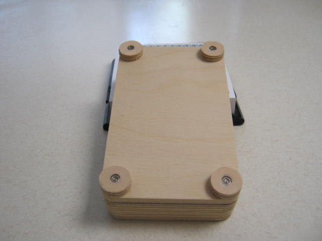
Bottom view:
![]()
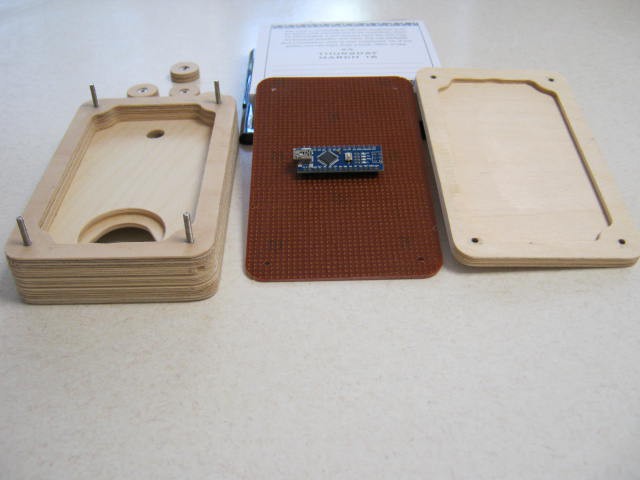
Disassembled:
![]()
So work remaining is to design the strip-board, the USB cable route and perhaps a varnish.
AlanX
-
Bell 103A2 Modem Debug
02/13/2017 at 14:34 • 1 commentLoopback Test
I had some problems with the audio loopback so I had to drop back to a direct loopback.
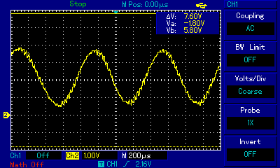
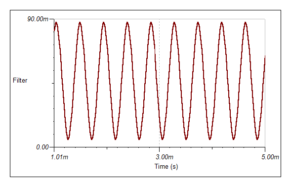
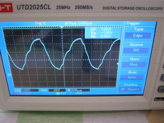
Here is the signal from the first stage lowpass:
![]()
Not pretty but functional. Some noise is probably a good idea for testing and optimising.
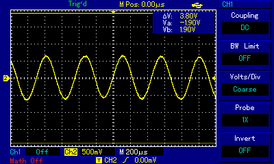
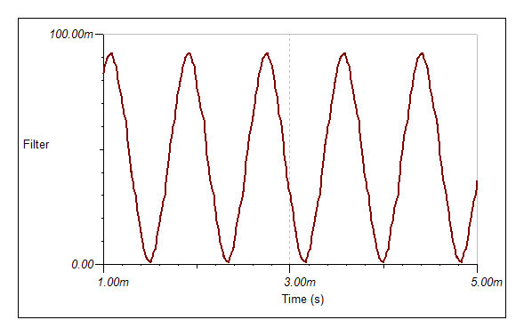
Here is the demodulator output:
![]()
Basically identical results for Answer or Originate configuration. What is not shown here is the decoder jitter.
Baud Rate Generator
The jitter associated with the baud rate generator was the main problem. It was missing the timeout flag. Fixed. It now only misses the occasion interrupt tick from the sample clock.
Demodulator Jitter
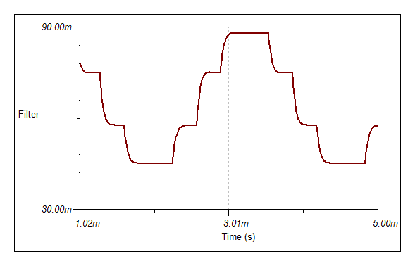
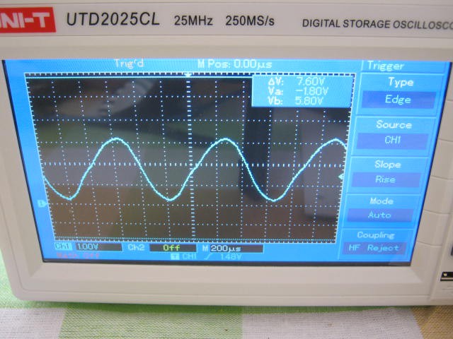
The jitter associated with demodulator is likely to be jitter from the sine wave generator and/or from the phase transition. Suppressing the high frequency noise by adding an additional low pass had no effect:
![]()
The only real hint is that jitter is much worse (x4?) with the higher frequencies suggesting jitter is from the sine wave generator.
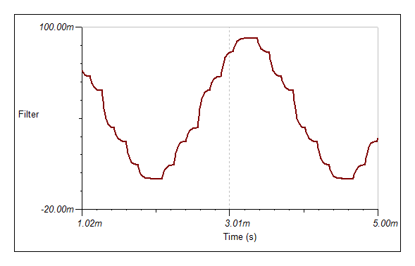
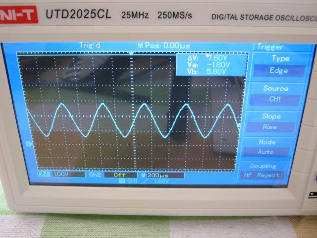
Turned off the binary signal (i.e. a single tone) and the jitter is clearly visible and in tune with the demodulator jitter. Here is the signal, even in this image you can see this signal moves around:
![]()
Bandpass Filters
Before I found the baud rate generator problem I reduced the band pass filter Q to good effect. After minimising the remaining jitter I will have to rework the band pass filters to see if I can increase the Q as I think suppressing the opposite channel still has merit.
Sine Wave Generator Investigations
Tried a 62.5kHz Fast PWM, 32 bit maths and a 256 sine wave lookup table (and variations in between). The sine wave looks great but slowly oscillates. The demodulator hates it! After double checking I find the frequency is off which means the Arduino cannot keep up (even with just the sine wave generator running). Back to 31.37 kHz.
Now I was caught out in that I thought the Phase Correct PWM frequency is half of the Fast PWM frequency of 62500 Hz. It is not! It is actually 31372.5 Hz. It pays to check the manual.
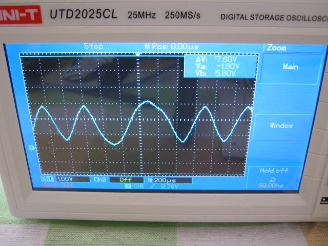
I have come to the conclusion that the jitter is mostly due to background interrupts by the Arduino bootloader. This probably means that I am losing interrupt ticks. I did drop the PWM to 7813 Hz to have a look, but the wave form was pretty poor:
![]()
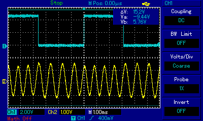
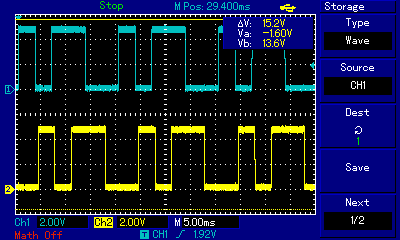
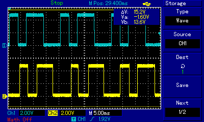
Data In Versus Data Out
Here is the Data In (blue) versus Data Out (yellow). Note that Data Out is delayed by about a bit:
![]()
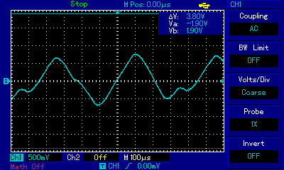
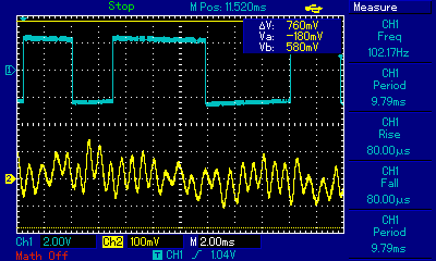
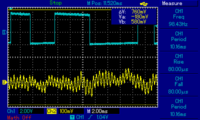
You might say what jitter? That was the low channel (1170 Hz), the high channel (2125 Hz) is not so good:
![]()
In reality the background jitter is just like a noise floor. It just sets a minimum for degradation by the telephone system. I could spend weeks investigating jitter and trying solutions but I feel I have a fair solution right now so I will move on.
Audio Loopback
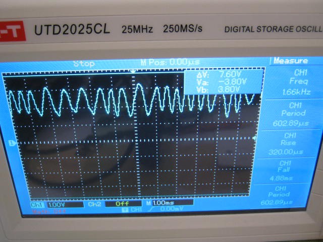
Now that I think I have the code working properly, here is the results of the audio (speaker and microphone) loopback for the low channel:
![]()
The signal looks to be all over the place but it detects okay with the usual jitter.
Here is the high channel:
![]()
Detection is good with the speaker to about 30 cm away. Without the speaker connected you get the usual spike chatter.
The microphone gain is far too high, someone talking in the room is stronger than the signal. But the next circuit board iteration has that fixed.
---
So lots of progress today! A working modem!
Alanx
-
Yet Another Project Log! Magic Numbers
02/11/2017 at 09:17 • 0 commentsThe Search for Magic Numbers
I have been searching for magic numbers. Yes I use Excel to help (i.e. goal seek, solver, macros (mostly brute-force) and data tables).
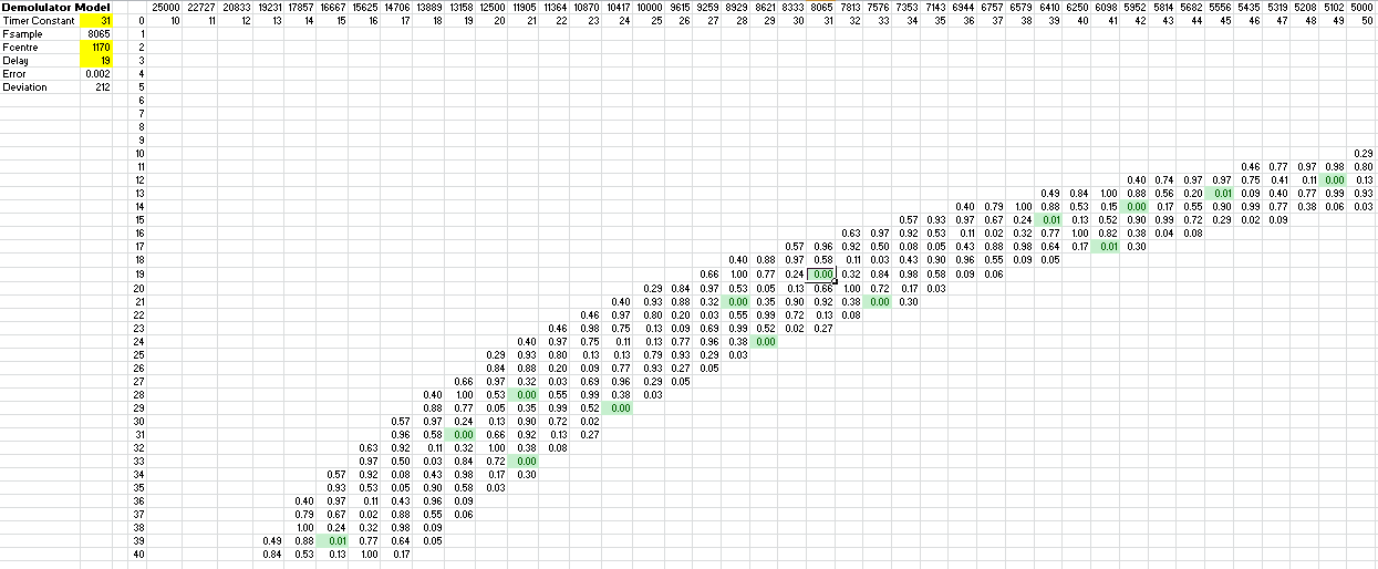
The Sample Frequency Search
Basically matching up the timer divider (i.e. Fsample = 16,000,000/64/n) and the delay number to find a correlation null at the centre frequency. We want a sample frequency that is between 7000 Hz and 10000 Hz to avoid aliasing within the telephone bandwidth and enough time for processing the signal between timer ticks. The correlation null need not be exactly zero. Here is the table for the 1170 Hz centre frequency:
![]()
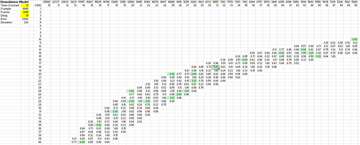
The frequency number (n) is at the top and the delay number (d) is on the left. The band is from 175 Hz to 250 Hz bandwidth. I have selected a cell near the middle (sample frequency 8069 Hz and a delay of 19). I chose this cell over the others as the table for the 12125 Hz centre frequency has a matching sample frequency (delay 18):
Using the same sample frequency simplifies the low pass filter coding.![]()
The Search for the Perfect Bandpass Filter
Here I used a brute-force Excel macro. I decide to use three stages and wanted a pretty close match in performance for the two centre frequencies. Here are the coefficients that I found:
Modem Answer Originate Units Fsample 8069 8069 Hz Fcentre 1170 2225 Hz Divisor 8 8 Q 1.78 2.16 Gain 1.3 1.3 A0 2 2 A1 0 0 A2 -2 -2 B1 8 -1 B2 -5 -5 Other channel suppression -29 -36 dB When considering filter coefficients you must avoid division by using arithmetic shift right. Therefore the divisor must be a power of 2. A low divisor reduces the risk of integer overflow.
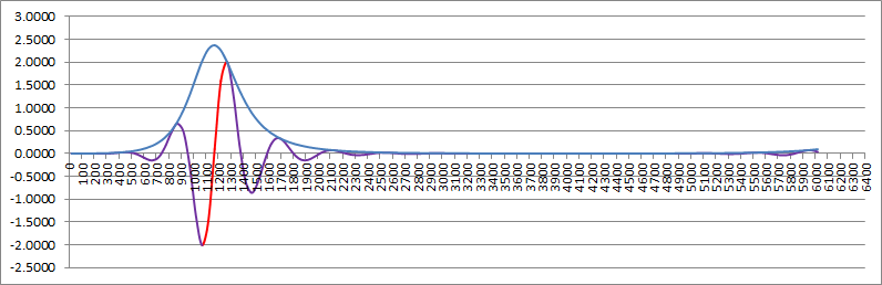
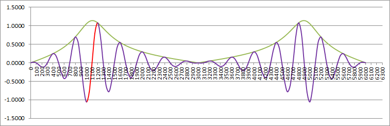
These filters should reject the other channel by about 30dB. This should be enough. Here is the answer modem (i.e. Fc = 1170 Hz) calculated response:
![]()
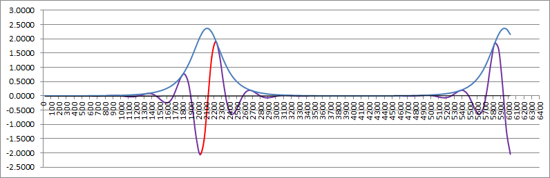
And the originate modem (i.e. Fc = 2125 Hz) calculated response:
![]()
Note the alias above 5000 Hz.
The Magic Biquad Frequency Analyser
You may have noticed I have been using a really cool graphs of the bandpass frequency response. Here is where I got it from:
The guy/gal who worked this out deserves a medal!
A BandPass Magic Number Generator
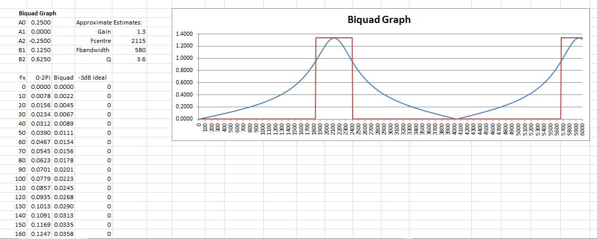
To date I have been using a brute-force (i.e. a dumb grid search) macro to find the integer parameters for my bandpass filters. If you don't know, integer problems are very hard (actually NP Complete). While it works, it is slow and being a bit of a perfectionist (it a genetic disorder) I have eventually got a quick spreadsheet method working. While it finds the best solution available, determining the quality of that solution (in practice the filter Q) is a bit difficult (there is a way but even a perfectionist can say why bother as it is a case of "take it" or "leave it" for the filter). Here is what it looks like:
![]()
I used biquad frequency response as a check:
![]() You may be able to see that the filter Q is closer to 3.6 than the design of 2.2.
You may be able to see that the filter Q is closer to 3.6 than the design of 2.2.I have posted the spreadsheet to the project if your interested.
Modem Simulations
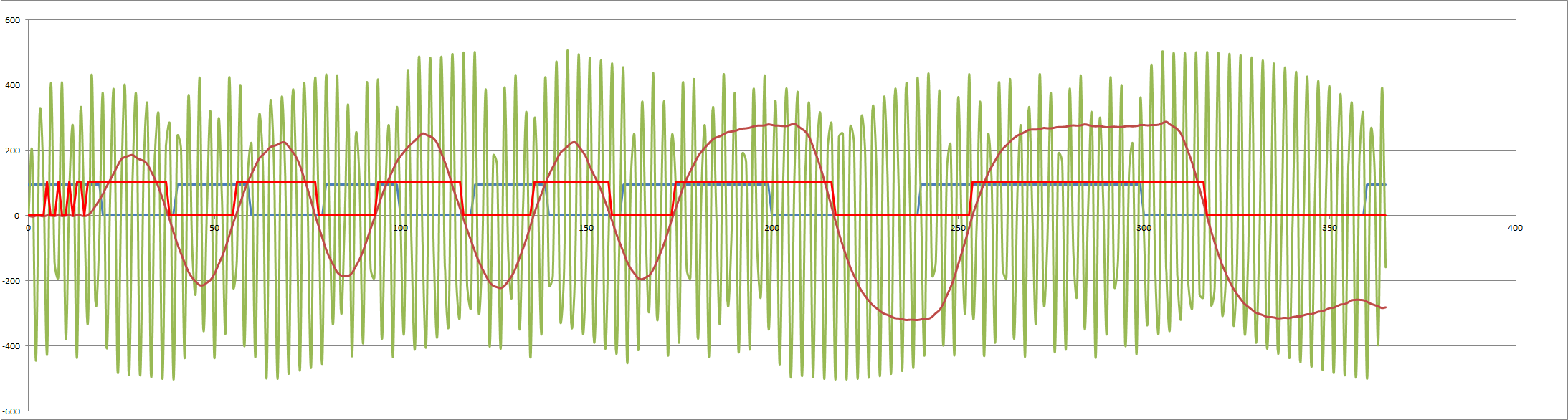
Finally here is the answer modem simulation (the originate modem simulation is similar):
![]()
Notes:
- The blue is the input data and the red the output data.
- The green signal is after the three stage bandpass (the input signal was 1022 pp).
- The brown signal is after the lowpass filter.
Next
Update the Arduino code the test. If all good then finish off the case.
AlanX
-
Generating Sine Waves
02/09/2017 at 23:55 • 0 commentsGenerating Sine Waves
Who thought this would be hard?
I have spent a week trying to work this out. Here is the pseudo code so far:
Calculate the Mark and Space ratios:
- A= int(Fsample/Fmark+0.5)
- B= int(Fsample/Fpace+0.5)
Find the lowest common multiple N of A and B:
- N = LCM(A,B)
Where N is the sine (iSin[]) lookup array size.
To generated the sine wave step through the array using Phase:
- Phase=Phase +N/A, for the mark frequency
Note: B=N/A
So:
- Phase=Phase +B
or
- Phase=Phase +A, for the space frequency
The Phase needs to roll back to the start on overflow:
- if (Phase>=N) then Phase=Phase-N
The sine wave is:
- Sine=iSin[Phase]
To reduce the sine look up array size by a constant (C) we can divide the Phase by the constant (C):
- Sine=iSin[Phase/C]
or
- Sine=iSin[Phase>>M], as the maths is much faster
The sample frequency is restricted and depends on the Arduino clock (16 MHz), the pre-scaler (timer dependent) and the PWM type.
So I have spent a day trying different combinations of Fsample and M to minimise the array size and the error. Nothing great found!
---
I thinks I need help (at least my partner thinks so)!
I found a paper (http://www.analog.com/static/imported-files/tutorials/MT-085.pdf) that although a bit complicated, shows a way out of this mess:
Set N to a power of 2, say 65536 (an unsigned int):
- B=65536*Fmark/Fsample
- A=65536*Fspace/Fsample
Then phase is:
- Phase=Phase+B
or
- Phase=Phase+A
Choose a sine array size that is a power of 2 , say 64.
- Sine=iSin[Phase>>(16-6)]
or
- Sine=iSin[Phase>>10]
Phase rollover is implicit with an unsigned int.
Here is the code for the ISR:
// TRANSMIT:
//   Phase Correct PWM frequency 31250 Hz
//   Originate modem Mark  frequency    1270 Hz (=2244)
//   Originate modem Space frequency    1070 Hz (=2663)
//   Answer modem    Mark  frequency    2225 Hz (=4666)
//   Answer modem    Space frequency    2025 Hz (=4247)
const byte iSin[64] = {
  128,140,153,165,177,188,199,209,
  218,226,234,240,245,250,253,254,
  255,254,253,250,245,240,234,226,
  218,209,199,188,177,165,153,140,
  128,116,103, 91, 79, 68, 57, 47,
   38, 30, 22, 16, 11,  6,  3,  2,
    1,  2,  3,  6, 11, 16, 22, 30,
   38, 47, 57, 68, 79, 91,103,116
};

volatile byte DataOut=0;
ISR(TIMER2_OVF_vect) {
  static unsigned int phase=0;

  OCR2A = iSin[(phase>>10)]; // Output on D11
  if (true) { // Set true for Originate Modem
    if (DataOut==0) {
      phase+=2244;             // Fspace (Originate modem)
    } else {
      phase+=2663;             // Fmark (Originate modem)
    }
  } else {
    if (DataOut==0) {
      phase+=4247;             // Fspace (Answer modem)
    } else {
      phase+=4666;             // Fmark (Answer modem)
    }
  }
}
Now is that not sweet code!
---
I used Phase Correct PWM instead of Fast PWM as it generates less interrupts rather than the phase correct feature.
Final note, don't put the iSin array inside the ISR like I did! It took ages to workout why the PWM was off frequency!
AlanX
-
Backward Channel Considerations
02/01/2017 at 11:28 • 0 commentsThe Forward Channel
I have simulated many options but I have not really done much better than the current setup. The backward channel without any additional filtering is suppressed nearly 20 dB. Really I have to wait until I physically test the modem with the presence of the backward channel before spending too much more time.
The Backward Channel
The backward channel is 387 Hz (space) and 487 Hz (mark). If I lowpass the signal (e.g. 585 Hz) and then down sample to 3300 Hz (from 13200 Hz) then the existing modem code will work fine for backward channel. The main problem is that the 2200 Hz frequency is aliased as 500 Hz. So I will need a good lowpass filter before the down sampling.
More thought is required.
Filter Madness
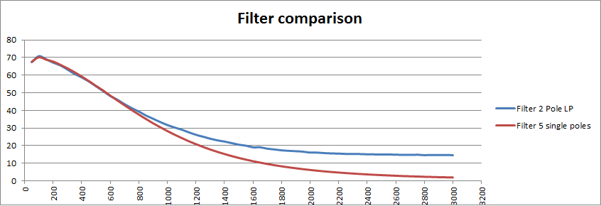
Spent a lot of time playing with filter parameters to avoid proper division (can only use arithmetic shift right). Looking at cascading single pole filters. Easier to design, numerically efficient and works more or less the same. Here is a 5 single pole versus the current two pole lowpass:
![]()
Code for the 558 Hz 2 pole lowpass:
- LP0=(S0+S1+S1+S2+41*LP1-13*LP2)>>5;
- About 7 us.
And for the 5 single pole version:
- A0=(S0+A1)>>1;
- B0=(A0+B1)>>1;
- C0=(B0+C1)>>1;
- D0=(C0+D1)>>1;
- E0=(D0+E1)>>1;
- About 6 us.
So the five single poles works better and is faster!
Modem Output
If I want to configure the modem for both forward and backward output then I will need to review the output filter. One option is to increase the number of steps for the DAC for the backward channel.
More thought is required.
More Code
Rewrote the code so the the modem can be send mode or answer mode. I have not tested it yet but I need to consider the digital to analog conversion (DAC) and the output lowpass filter. The question is do I really need to try so hard to filter out the DAC quantization. Here is the what I am thinking:
![]()
At 2 bit 2200 Hz is fine:
![]()
And at 1200 Hz the wave form is still okay:
![]()
But at 387 Hz:
![]()
This will probably not work will (but I have not tried).
But if I use three bit, the wave form is greatly improved:
![]()
So perhaps 4 bit is the way to go. The advantage of the above circuit is that the amplitude does not vary very much and the power level is probably about right (125 uW) but can be increased in necessary.
Four Bit Version
Here is a four bit version showing 387 Hz and 2200 Hz:
![]()
With the four bit version the resistor ladder network does not have to compensate for the lack of bits. The 25 R resistors are the uP source impedance. The power level is about 0.1 mW which will probably need to be scaled back.
PWM Check
Just to double check, I reconsidered PWM. First the ripple was about the same for the same RC values using a PWM frequency of 31.25 kHz for only the 387 Hz case. However, ripple frequency for the PWM much higher will present as a 4850 Hz alias for the answer modem (i.e. 2200/1200 Hz) and a 1750 Hz alias for the send modem (i.e. 487/387 Hz) so will not present a problem (if any gets through the phone line filters). For the answer modem the sensitivity to the 4850 Hz signal is attenuated about 20 dB (the attenuation is similar for the send modem). So the PWM option will work as well.
Now at this time you may be wondering why I did not go with PWM in the first place? Well basically I could not model the PWM frequency affect on the modem response then!
I like simple so back to PWM:
![]()
The PWM filter works for low frequencies but the ISR generates a square wave for 2.2kHz. Pretty ugly. Added another capacitor across the speaker to clean it up. Looks more like a triangle wave but good enough. Here is the PWM circuit:
![]()
AM Demodulator
I had a play with the decoder and reworked it as an AM demodulator:
![]()
If I wanted to create my own protocol I could mix binary FSK with binary ASK!
Bell 103A Work
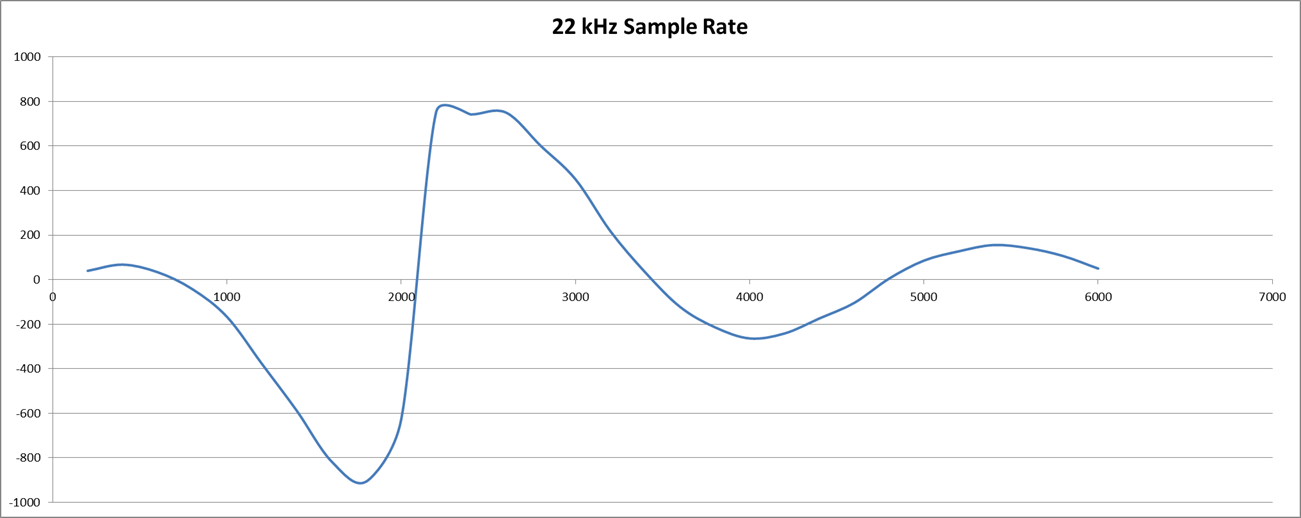
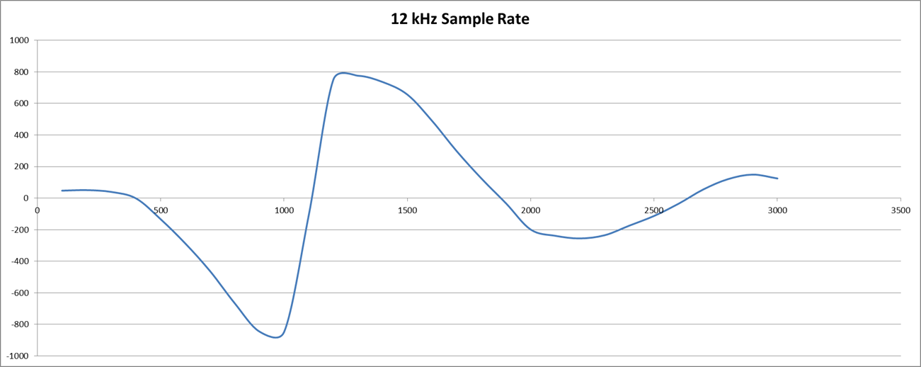
The first observation is that there are a number of configurations that need to be tested and it is rather a headache! First is to determine suitable sampling rates for the originate and answer decoders. Integer multiplies work best and the sample rates determined were: 22 kHz (2200/2000 Hz) and 12 kHz (1200/1000 Hz). The Biquad LP (330/140 Hz) was unstable so a two stage low Q (0.5 each stage) state variable low pass filer was used. For the band pass (2200/1100 Hz) I used a medium Q (5.5) biquad. It works but transit ripple causes problems. Further work is required. Here is the frequency response for a delay of 8 for both originate (22k) receive (2200/2000 Hz) and answer (12k) receive (1200/1000 Hz) modem decoders:
![]()
![]() Pretty nice as only the sample rate was changed.
Pretty nice as only the sample rate was changed.But I get some decoder issues (probably phase (beat) issues) (note the variance in the first three positive peaks):
![]() If I change the sample frequency to 13200 Hz (from 12000 Hz) and delay to 9 (from 8), the issue disappears?
If I change the sample frequency to 13200 Hz (from 12000 Hz) and delay to 9 (from 8), the issue disappears?![]() I am going to have to understand/model the demodulator function more directly.
I am going to have to understand/model the demodulator function more directly. The other issue I ran into was that the transmit frequencies are difficult to generate from the receive sample clock (Timer0) so I need to look at using either the PWM timer (Timer2) or Timer1 to handle the transmit frequencies.
So there is still a lot of work getting everything working together in the best possible way.
Mathematical Help
Trial and error is expensive so I spent the afternoon doing the decoder maths. Not hard, end up with:
- Correlation = 1/2*Cos(-2*Pi*f*d), where 'f' is the frequency and 'd' is the delay.
As I am interested when the correlation crosses the axis (i.e. the centre frequency) the function simplifies to:
- d = (2*n+1)/4*Fsample/Fcentre, where 'n' is a positive integer.
Note I am restricting myself to integers (non-integers will work but are not optimal).
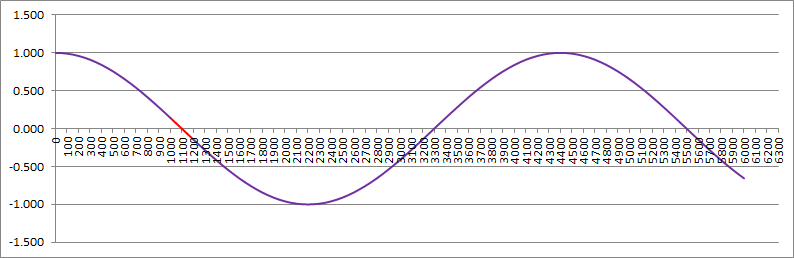
For n=0 I get d=3 (assuming 13200 Hz sample rate) and the response looks like this:
![]()
The red is the range of interest (note the correlation is negative).
For n=1 or d=9 (what I was using) the response is:
![]()
Better but the decoder has a better response to other frequencies that are not of interest. Thus the need for a bandpass filter. Without a bandpass fllter the optimal response is n=5 or d=33:
![]()
At least here no other frequency is better.
By inspection you can work out that the optimal delay is:
- d = Fsample/2/(Fmark-Fspace)
Optimal Sample Rate
The next problem is what is the optimal sample rate. Tough! From the above maths I can only say it is a multiply of 400 Hz (= 2*(Fmark-Fspace). I know I get a good result at 13200 Hz and 12000 Hz but can I go lower?
It has to be greater than 2 x Fmark (2400 Hz). If we use this number then the correlation depends on the signal to sample phase. Not good. I can now say it has to be at least 3 x Fmark to avoid really bad "beating".
I ran a few simulations until I realised that the signal generator was not working correctly. Now that it is fixed, the decision on the sample rate is really based on the bandwidth of the telephone system (i.e. from 300 Hz to about 3400 Hz). Therefore the minimum sample rate should be about 6000 Hz. Here is the calculated sensitivity (combined modem and bandpass filter) for a 6000 Hz sample rate:
![]()
Note the alias on the right beyond 3000 Hz.
Updated Modem Code
Here are the updated modem results.
The originate 1000/1200 Hz:
![]() And the answer 1200/2200 Hz:
And the answer 1200/2200 Hz:![]()
Recalibration
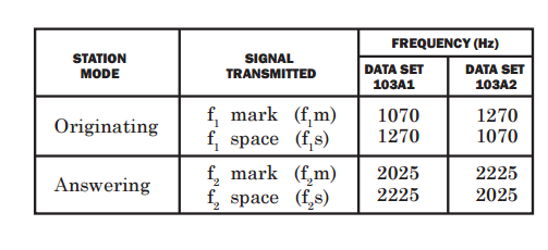
As I seem to have the modem decoders working properly, it is about time I adjusted the frequencies to match the specifications:
![]()
Note I am working with the Bell 103A2 set.
AlanX
-
A Modem Case
01/29/2017 at 12:55 • 0 commentsA Modem Case
Spent the day designing a case for the modem. Basically a piece of 18 mm thick MDF.
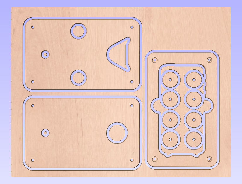
I chose MDF as it has a soft edge when cut and should suit this application. The design consists of a top layer for the iPhone and mounts for the microphone and speaker. The second layer (to do) will hold the electronics etc. The iPhone will be fully below the top of the MDF so that the modem case can have a lid. Here is the top layer:
![]()
This morning I backed out of the "carved" modem case and redesigned a plywood version:
![]()
Th disks are temporary feet.
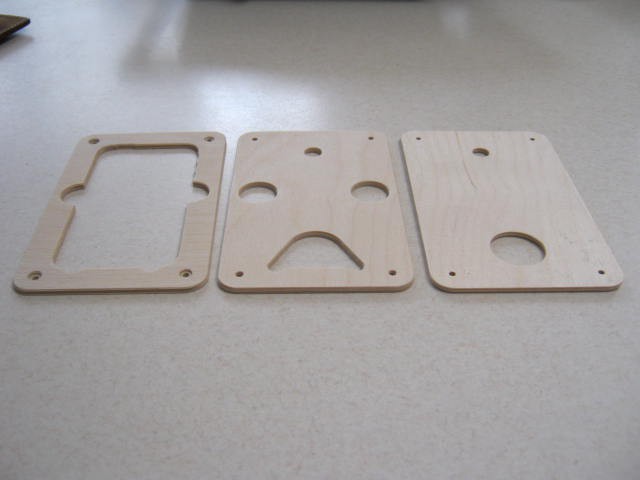
Here are the cut pieces:
![]()
And assembled with the microphone and speaker in place (to be glued later):
![]()
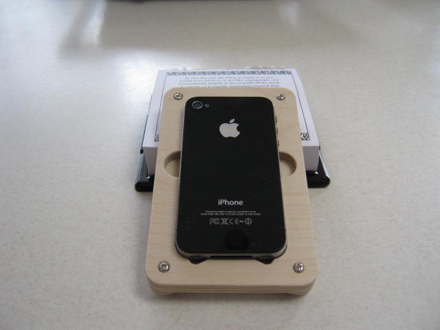
And the iPhone happily sitting on top:
![]()
Now to design the electronics compartment. The simplest power supply and serial interface is to use the Arduino/Nano USB plug and a USB cable. I will also need a switch (on the base) for send or receive mode.
Half duplex means you need two modems and iPhones on each end (unless I can get the back channel to work).
Testing Speakers
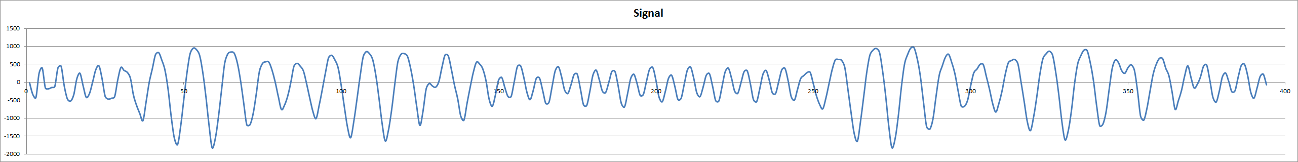
Even though I have made the top of the case for the small speaker I had not actually tested the speaker. I assumed that the smaller speaker with less inertial would be better - wrong!
Here is the small (26.7 mm diameter) speaker signal as recorded by the Nano:
![]()
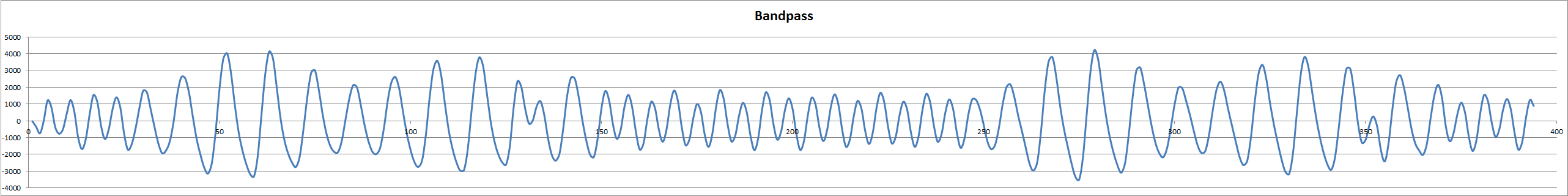
Looks good except for the AM modulation. Here is the signal after the bandpass:
![]()
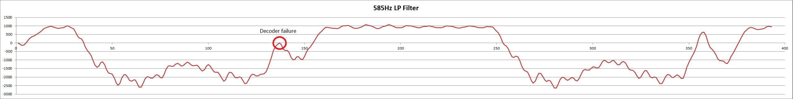
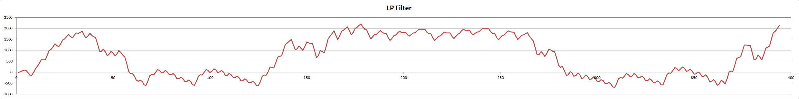
Looks even better except for the AM modulations. Here is the signal after the lowpass:
![]()
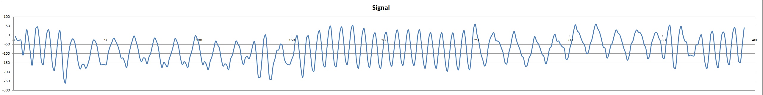
See how the AM modulation upsets the decode and in fact the decode fails (repeatedly at this point). Here the medium (39.5 mm) speaker signal:
![]()
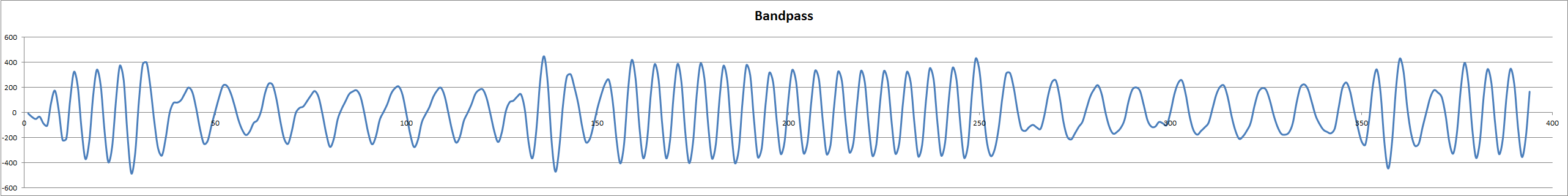
It looks worse but look at the signal after the bandpass:
![]()
It is pretty good. Here is the signal after the lowpass:
![]()
No problems. All of the above is repeatable. No difference with a Zobel network and no hint of issues when measuring the speaker terminals.
So I will have to rework the case for the larger speaker.
---
I have some 6.4 mm thick plywood in the shed so I will cut the electronics enclosure and the base tomorrow. I will cut the strip-board the same size as the other pieces and sandwich it near the base.
I don't have bolts long enough for the complete sandwich pile but that can be fixed later.
Designed the rest of the case. Decided to glue the top sandwiches and conceal the bolts for the bottom sandwiches.
---
Cheap Chinese CNC Machine
I have a cheap Chinese CNC machine, so I can make neat little wooden objects (such as the modem case) but I can tell you these machines are hard to use and are very slow:
- They overheat (the heat-sinks for the drivers are not sufficient for continuous operation).
- The cables break after a short while.
- They are not rigid enough to go fast.
- The USB driver, USB controller or driver interface occasionally stops working.
- Even if the driver power switch is off the spindle motor is still live!
- The table is not level.
- They don't come with sensible instructions are usage recommendations.
On the user side:
- Makes design mistakes.
- Does not properly secure the work piece.
So tonight I had one success out of three attempts. Not happy! I will have another go tomorrow, five pieces remain. Here is the stack so far:
![]()
I have re-cut the speaker hole to fit the 40 mm diameter speaker and added a 6.4 mm thick cover to hide the assembly bolts. The iPhone will now sit just below the top of the case.
Speaker Tests
I tested the modem at 1200/2200 Hz and not too bad.
Tested the modem at 400/500 Hz and evidence of strong AM modulation upsetting the demodulator:
![]()
I suppose it is too much to ask for a speaker not to resonated at any frequency of interest. Not keen on a two speaker design.
I wonder if paper cone speakers are better? I will have to buy a couple and try them.
I suspect stopping the speaker from resonating may be a bit of an ask so I need to look at suppressing AM modulation in software or going directly to a FM discriminator. Looking at he above, it looks like close to 100% AM modulation, that may be difficult to remove.
Thoughts on Speakers
Unsoldered a small paper speaker from my 2 transistor MW radio:
![]() But it was worse, AM modulation (~120 Hz) and frequency was way off (slow to respond):
But it was worse, AM modulation (~120 Hz) and frequency was way off (slow to respond):![]()
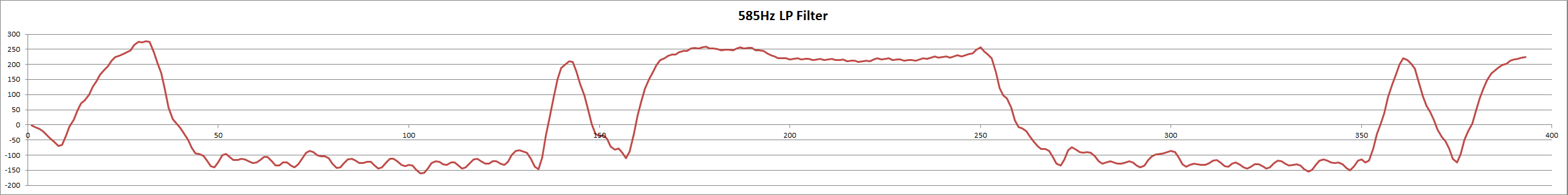
This is what the LP is producing:
![]()
Three More Speakers Tested
Bought three more small speakers, 30 mm mylar and 50 mm mylar and a 30 mm metal ("modem") speaker. The modem and 50 mm speakers failed but the 30 mm just worked (or could with improved filters). So a quality speaker (and these speakers are not quality) would likely work. However I have move on to the Bell 103A specification so the issue is not important anymore.
AlanX
-
Trial and Error
01/25/2017 at 00:54 • 0 commentsTrial and Error
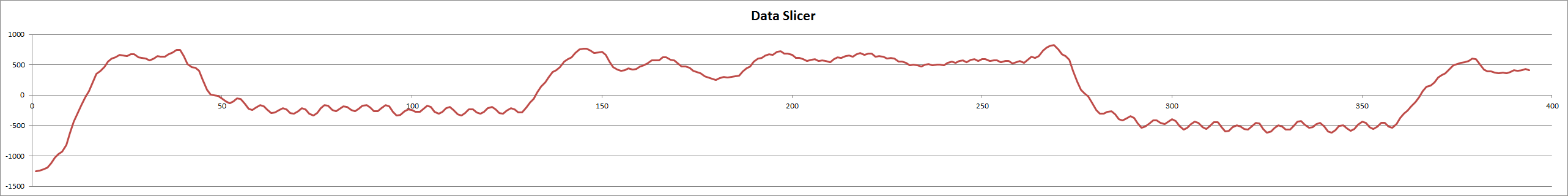
Optimising the code is tricky as there are so many parameters. One approach is to extract the data from the Arduino and model the code in Excel. Once the Excel model faithfully mirrors the Arduino the the parameters can be tested. Here are some examples (cut down to fit the Hackaday webpage width):
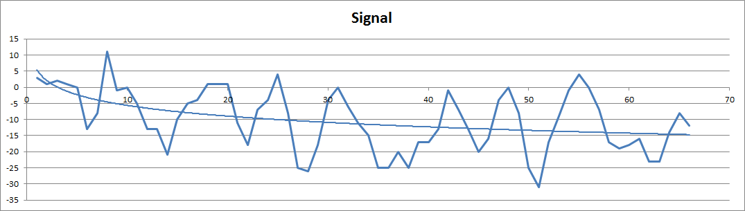
First the input signal recorded from the Arduino (note the pre-amplifier bias shift):
![]()
Now with the bias removed:
![]()
Now mixed:
![]()
Now after the LP filter (and this still amazing me):
![]()
Now with the DC bias removed:
![]()
Now after non-return to zero detection:
![]()
You will note that the out put data is delayed by about 1 bit and the duty cycle is somewhat jittery, That is because the signal is 100mv pp and the background noise is about 50mv pp. If the signal is higher the duty cycle jitter disappears. The main problem with the detector is that it is sensitive to background impulse noise (false highs).
More Code improvements
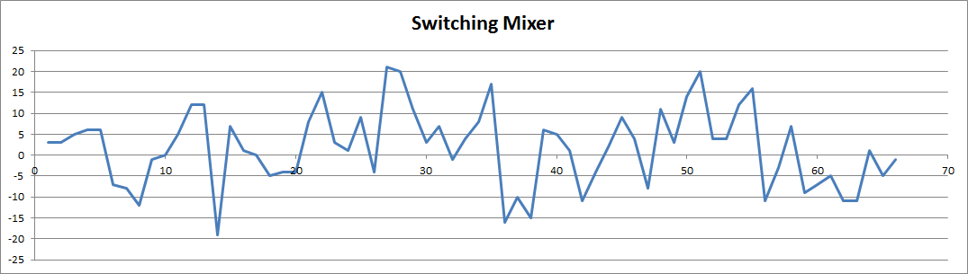
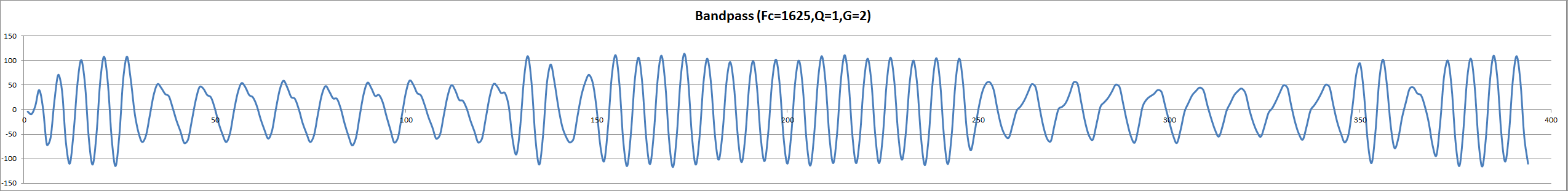
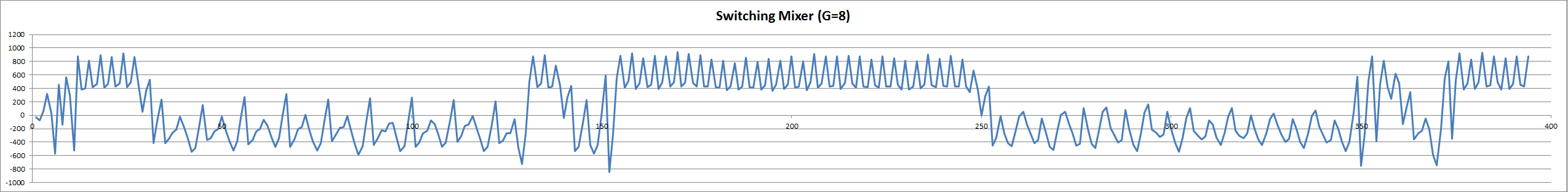
Spent the last few days testing code. I think I am at the end (can't think of anything else to try). The final version consists of a bandpass, switching mixer and a low pass:
- Bandpass: Fc=1625 Hz, Q=1, Gain=4
- Switching mixer: Delay=6, Gain=4
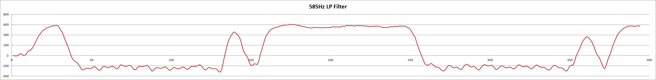
- Low pass: Fc=585 Hz (critically damped)
The DC bias problems at the switching mixer are solved by the bandpass filter much better than the DC bias filter.
The DC bias problems after the low pass was solved by increasing the gain (i.e. an integer maths problem).
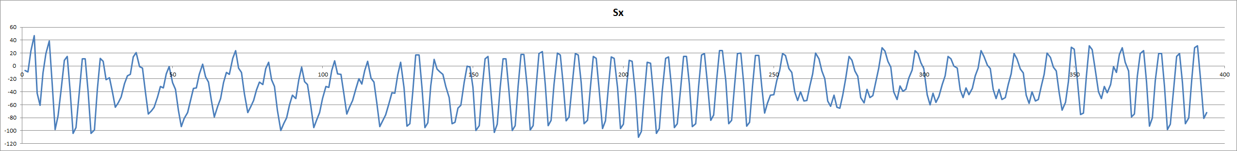
Here are the signals:
The input signal:
![]()
After the bandpass filter:
![]()
After switch mixing:
![]()
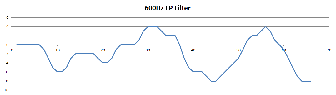
After the lowpass filter:
![]()
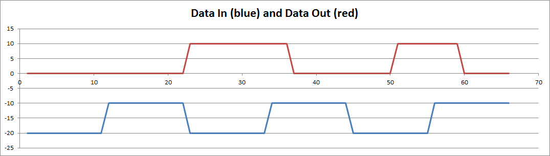
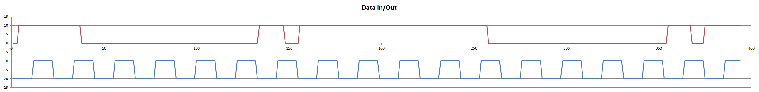
And finally the demodulated signal (shown against the buad clock):
![]()
The input signal about 0.77v pp and the demodulator works down to 0.001mv pp (+/1 LSB of the ADC!).
Execution Time
The measured execution time of the ISR (including the ISR overhead of 2.6 us) was:
- 33.3 us total
- 8.6 us to drive the output wave form
- 20.1 us to decode the input signal (including 17.2 us for the ADC conversion)
The total time between interrupts is 75.7 us.
A very tight fit if I want to use a 150 baud back channel as per the specification.
Here is the current code:
// Bell 202 modem
#define Fspace     1200
#define Fmark      2200
#define Fsample   13200
#define Baud       1200
#define sampleTicks  66     // sampleTicks = Fsample / Fmark * Fsample / Fspace

// 2 bit Sine table for Fsample equal to 13200 Hz
const byte sin2Bit[sampleTicks] = {
  2,2,2,2,2,2,2,2,
  3,3,3,3,3,3,3,3,3,3,3,3,3,3,3,3,3,
  2,2,2,2,2,2,2,2,
  1,1,1,1,1,1,1,1,
  0,0,0,0,0,0,0,0,0,0,0,0,0,0,0,0,0,
  1,1,1,1,1,1,1,1
};

// Define various ADC prescaler
const byte PS_16=(1<<ADPS2);
const byte PS_32=(1<<ADPS2)|(1<<ADPS0);
const byte PS_64=(1<<ADPS2)|(1<<ADPS1);
const byte PS_128=(1<<ADPS2)|(1<<ADPS1)|(1<<ADPS0);

void setup() {
  pinMode(A0,INPUT);                               // Audio input
  pinMode(12,OUTPUT);                              // Digital data output
  pinMode(11,OUTPUT);                              // Audio output bit 1
  pinMode(10,OUTPUT);                              // Audio output bit 0
  pinMode(LED_BUILTIN,OUTPUT);                     // Test loop speed
  Serial.begin(9600);
  // Set ADC prescaler (assume a 16 MHz clock)
  ADCSRA&=~PS_128;                                 // Remove bits set by Arduino library
  ADCSRA|=PS_16;                                   // 16 prescaler (1 MHz)
  // About 17.2 us to return an ADC value but only good for 6 bits (probably more)

  cli();                                           // Disable interrupts
  // ATmega48A/PA/88A/PA/168A/PA/328/P
  // Use Timer 0 for sample rate (13.2 kHz)
  // Note delay() and millis() will no longer work (use microseconds() instead)
  TIMSK0 = 0;                                      // Timer interrupts OFF
  TCCR0A = (2 << WGM00);                           // CTC mode
  TCCR0B = (2 << CS00);                            // prescaler 8, 2 MHz clock
  TIMSK0 = (1 << OCIE0A);                          // COMPA interrupt
  OCR0A = 151;                                     // Sample rate: 2 MHz/152 = 13.2 kHz
  sei();                                           // Enable interrupts
}

// Total execution time 33.3 us including interrupt overhead of 2.6us
volatile byte DataIn=0;
volatile byte DataOut=1;
volatile byte baudTick=11;
ISR(TIMER0_COMPA_vect) {
  static byte Phase=0;
  static int SX0=0,SX1=0,SX2=0;
  static int BP0=0,BP1=0,BP2=0,BP3=0,BP4=0,BP5=0,BP6=0;
  static int MX0=0,MX1=0,MX2=0;
  static int LP0=0,LP1=0,LP2=0;

  // Audio output (8.6 us)
  PORTB=(PORTB&0b11110011)|(sin2Bit[Phase]<<2);
  if (DataOut==0) {
    Phase+=6;
  } else {
    Phase+=11;
  }
  if (Phase>=sampleTicks) Phase-=sampleTicks;
  // Done when baudTicks==0
  if (baudTick>0) baudTick--;

  // Decode the data (22.1 us)
  SX2=SX1;SX1=SX0;
  BP6=BP5;BP5=BP4;BP4=BP3;BP3=BP2;BP2=BP1;BP1=BP0;
  MX2=MX1;MX1=MX0;
  LP2=LP1;LP1=LP0;

  SX0=analogRead(A0)-512;                     // Get sample
  BP0=BP1+SX0-SX2-(BP2>>1);                   // 1625Hz (Q=1) bandpass (gain x4)
  MX0=(BP6>=0)?BP0:-BP0;                      // Switching mixer
  MX0=MX0<<2;                                 // Increase gain (x4)
  LP0=(MX0+MX1+MX1+MX2+41*LP1-13*LP2)>>5;     // 585 Hz low pass filter

  // Test correlation and set D12
  if (LP0>=0) {
    DataIn=1;
    PORTB|=0b00010000;                        // Set D12 high
  } else {
    DataIn=0;
    PORTB&=0b11101111;                        // Set D12 low
  }

}

void loop() {
  static byte lastBaudTick=0;
  static byte temp=1;
  static byte i=0;
  // A test frame 0x00 and 0xFF with a start and stop bit.
  byte test[20]={1,0,0,0,0,0,0,0,0,0,1,0,1,1,1,1,1,1,1,1};

  if (lastBaudTick!=baudTick) {
    digitalWrite(12,DataIn);
    if (baudTick==0) {
      baudTick=11;
      DataOut=temp;
    } else if (baudTick==1) {
       temp=test[i++];
       if (i>=20) i=0;
    }
    lastBaudTick=baudTick;
    // Output loop toggle: should be almost 6600 Hz and steady
    digitalWrite(13,!digitalRead(13));

  }
}
Limits of DSP and Integer Numbers
The 1625 Hz, Q of 1 band-pass filter works exceptionally well with integer numbers. Trying to suppress the out of band frequencies has proven difficult. The coefficients of low frequency (high pass) filters are not kind (i.e. are very small) resulting in "integer DC bias" upsetting the switching mixer.
I did try doubling up the bandpass but the Q increases and upsets the demodulation and the low Q coefficients introduced high frequency noise to the demodulator (integer maths problems).
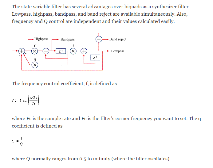
The current IIR filters are based on "Biquad" equations. Apparently State Variable (SV) filters are preferred for low frequencies. Here is the DSP verrsion of a SV filter:
![]()
(source: http://www.earlevel.com/main/2003/03/02/the-digital-state-variable-filter/)
Converting the DSP diagram into code I get:
- lp[n]= lp[n-1] + f * bp [n-1]
- hp[n] = sx[n] - lp[n] - q*bp[n-1]
- bp[n] = f * hp[n] + bp[n-1]
- nx[n] = hp[n] + lp[n]
Where sx[n] is the signal. This simplifies to:
- lp= lp + f * bp
- hp = sx- lp - q*bp
- bp = f * hp + bp
- nx = hp + lp
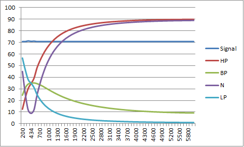
Plotting the filter response I get for an integer 0.5 Q notch filter (N) centred on the back channel centre frequency (434 Hz):
![]()
Forget the ripple as this is due to the both integer maths and limits of my spreadsheet model. Here is a floating point version:
![]()
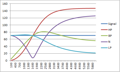
So it works well but you do need to check the actual response Consider the 1 Q 1625 Hz filter:
![]()
The band pass is more like a high pass (unless my maths is wrong)!
The notch filter works well but introduces a DC bias to the switching mixer. This can be mitigated by increasing the gain before the notch filter but I think I have to wait until I get to the point of actually needing to deal with the back channel.
AlanX
-
Modem Version 2
01/23/2017 at 02:56 • 0 commentsModem Version 2
Here it is:
![]()
Testing the Output
Here is a 1200Hz output at the DAC:
![]()
An after the low pass filter:
![]()
The designed peak to peak voltage is 3v. The output is offset to maximise the emitter follower voltage swing.
Same again for 2200Hz:
![]()
And after the low pass filter:
![]()
The designed peak to peak voltage is 2v.
Here is a binary signal after the low pass filter:
Note the amplitude modulation.![]()
Here is a random signal after the low pass filter:
So at this point all good.![]()
On the Receiving Side
The modem did pick up and demodulate a 500 uW audio signal from the speaker at about 1 cm away from the microphone but the microphone and transistor amplifier are rather non-linear with 1 to 2 volt voltage swings and is demodulating the amplitude modulation on the input signal:
![]() Note that the top of the signal has less range than the bottom of the signal.
Note that the top of the signal has less range than the bottom of the signal.Demodulation Updates
Had some problems demodulating the audio signal. Found some coding errors introduced in the last code update. Fixed. I also reworked the high pass to more aggressively remove the DC bias and to undo the low pass mark/space amplitude differences.
Here is the audio signal (~0.7 vpp) after the pre-amp and the demodulated signal (note that the demodulated signal is delayed by about 1 bit:
![]()
Have to be happy about this!
More work is required because demodulation fails at less than 0.5 vpp. With about 500 uW of speaker power and the speaker about 1 cm away from the microphone, the audio signal amplitude post the pre-amp is about 1 vpp (about where I want it).
Perhaps I need to consider some automatic gain control (AGC)?
Fine Tuning the Code
Debugging interrupt service routines (ISR) on an Arduino is hard work. You cannot just print debug information from inside the ISR. There are ways around this.
Anyway, I exported the variable data, line by line, checking and correcting. Had to relearn operator precedence order, and changed the DC bias code to something I found on the Internet (thanks: sam-koblenski.blogspot.com.au/2015/11/everyday-dsp-for-programmers-dc-and.html). Added another DC bias adjustment to the correlation output. It works very well now, down to just above the noise level (i.e. the fan of my oscilloscope delivers 100 mV pp post the pre-amplifier). Here is the demodulator code:
  // Decode the data
  X1=X0;
  Y6=Y5;Y5=Y4;Y4=Y3;Y3=Y2;Y2=Y1;Y1=Y0;
  Z2=Z1;Z1=Z0;
  F2=F1;F1=F0;
  G1=G0;
  Sx=analogRead(A0)-512;                  // 18 us
  X0=Sx+(3*X1>>2);Y0=X0-X1;               // Remove DC offset
  Z0=(Y6>=0)?Y0:-Y0;                      // Switching mixer
  F0=(Z0+Z1+Z1+Z2+F1*40-F2*12)>>5;        // 600 Hz low pass filter (8 us)
  G0=F0+(3*G1>>2);H=G0-G1;                // Remove DC offset
  DataIn=(H>0)?1:0;                       // Test correlation
Note: all variables are 16 bit integer.I don't think I need any more sensitivity but if I did, then filtering off of the high frequency noise would help (i.e. the demodulator is sensitive to any frequency above 1700 Hz as the mark frequency). I could roll off the microphone a little faster by adding a 2.2uF across the microphone pins. Actually, that did not work, it made it worse - parasitic oscillation? Here is the current strip-board layout:
Other options to reduce the noise is a high-pass in hardware or software.![]()
TBC...
AlanX
-
Working Out the Audio Path
01/22/2017 at 01:57 • 0 commentsWorking Out the Audio Path
Microphone Estimate Check
Here is my estimate for speaking into a microphone 25 mm away:
Speaking into a microphone Estimate Voice at 1 m 60.0 dB SPL (1 W / 1 m) No Power Adjustment 0.0 dB SPL (uP) -> V rms (the magic number!) -74.0 dB Microphone Sensitivity -63.0 dB Microphone Rated at 1k Load 0.0 dB Assume an effective 25 mm mouth to microphone spacing 32.0 dB Amplifier Gain (x1) 0.0 dB Voltage (rms) -45.0 dB Voltage (rms) 5.623 mV rms Voltage (pp) 15.905 mV pp
So is the mathematics right?Jack Smith (www.cliftonlaboratories.com/microphone_output_level.htm) piblished:
"The image below is at a speaking level more typical of what I would use in a normal QSO. Although there are a few peaks of 40 mV or more, the majority of the speech is around 20 mV peak-to-peak."
![]() So my estimate is reasonable.
So my estimate is reasonable.iPhone Output Level
Next, what is the output level of the iPhone in normal handset mode?
Hard to find on the Internet but a "dial tone" was quoted at 80 dB. This sounds okay, 80 dB is the level where you raise your voice to be heard and beyond that you risk long term hearing damage.
On that basis I can expect 4 vpp from the microphone (assuming I use the standard 1k load resistance, the microphone sensitivity is proportional to the load resistance within limits):
Dial Tone Estimate Telephone Dial Tone 80.0 dB SPL (1 W / 1 m) No Power Adjustment 0.0 dB SPL (uP) -> V rms -74.0 dB Microphone Sensitivity -63.0 dB Microphone rated at 1k load 0.0 dB Assume an effective 10 mm speaker to microphone spacing 0.0 dB Amplifier Gain (x1) 0.0 dB Voltage (rms) -57.0 dB Voltage (rms) 1.413 mV rms Voltage (pp) 3.995 mV pp Here I have had to assume an effective speaker to microphone distance of 10 mm.
Modem Speaker to iPhone Estimate
Here I have made two calculations: the first is normal speaking into an iPhone and the second the modem. The main difference is the power and distance from the "speaker" to the microphone:
Voice to Iphone Speaker Sensitivity 60.0 dB SPL (1 W / 1 m) No Power Adjustment 0.0 dB Distance Correction (50 mm) 26.0 dB Sound Level 86.0 dB Speaker to Iphone Speaker Sensitivity 80.0 dB SPL (1 W / 1 m) Power Adjustment (4 mW) -48.0 dB Distance Correction (10 mm) 40.0 dB Sound Level 72.0 dB There is a difference af 14 dB (x5) but this is well within the AGC range of the iPhone.
So the current design is workable.
iPhone to Modem Microphone Estimate
This question is more about the amount of gain required for the modem microphone:
Modem Receive Estimate iPhone Output 80.0 dB SPL (1 W / 1 m) No power adjustment 0.0 dB SPL (uP) -> V rms -74.0 dB Microphone Sensitivity -63.0 dB Microphone rated at 1k load 0.0 dB Assume an effective 10 mm speaker to microphone spacing 0.0 dB Amplifier Gain (x200) 46.0 dB Voltage (rms) -11.0 dB Voltage (rms) 0.283 V rms Voltage (pp) 0.799 V pp As the target average uP signal is about 0.7 vpp in order to maximise the dynamic range (5 v down to 0.1 v), a microphone gain of x200 is required. An LM386 would work well here.
The AM4011 Microphone
Checking the bias current for the AM4011 microphone:
Voltage across microphone Microphone Current 2.2 v 0.31 mA 4.4 v 0.32 mA 7.7 v 0.36 mA Based on the above measurements, a 5v supply and a 10k load resistor will work fine (approximately 2 volts across the microphone). This suggests a 20 dB gain improvement over the 1k load resistor test condition.
This suggest I will have to reduce the microphone amplifier back to maintain 1 vpp:
Modem Receive Estimate iPhone Output 80.0 dB SPL (1 W / 1 m) No power adjustment 0.0 dB SPL (uP) -> V rms -74.0 dB Microphone Sensitivity (rated at 1k load) -63.0 dB 10k Microphone Load Resistor 20.0 dB Assume an effective 10 mm speaker to microphone spacing 0.0 dB Amplifier Gain (x25) 28.0 dB Voltage (rms) -9.0 dB Voltage (rms) 0.353 V rms Voltage (pp) 0.999 V pp We will see if the microphone amplifier can be dropped back to a gain of only 28 dB!
Microphone Test In-Circuit
I assembled Modem V2 and checked the microphone circuit. The microphone worked well but only had 0.9v across it? Checked the circuit for wiring errors and incorrect component values, no faults found. Took the microphone out and checked it again (2.17v with a 10k resistor). Now I know the power supply for the test is 5.22v and the Nano gives out only 4.69 volts and I included a 1k resistor in series with the 10k resistor for the decoupling capacitor but 0.9v, really? Eventually I worked out that the decoupling capacitor was bad so I replaced it. I decided to bump up the microphone voltage by replacing the 10k resistor with a 6k8 resistor. The microphone voltage is now 2.15v in-circuit. I have another microphone which measured 1.8v in the same out of circuit test, so good to be above 2v in -circuit.
With speaking normal level voice at 0.5m I am getting about 0.5vpp. My dog barking at the rubbish truck 3m from the microphone pull 5vpp.
A 500uW signal from the modem speaker pulls 1vpp at 1cm.
AlanX
-
The Audio Interface
01/16/2017 at 05:32 • 9 commentsThe Audio Interface
Connecting the microprocessor (uP) to an 8 ohm speaker and to an 8 ohm speaker used as a microphone is tricky. Tricky if you want it clean (no PWM in the out put) and simple (i.e. low part count and garden variety components).
Op Amps
The problems here are simple power supply, voltage swing, input noise and output current capacity (i.e. output impedance).
The old single supply contenders (from my local electronics store) are:
- LM324
- LM3900
- CA3140
With a newer:
- LMC6482 or LMC6384.
None of these are low noise but the LMC6482/4 is rail to rail and rated at 600 ohm output impedance. So none of them will drive an 8 ohm speaker directly.
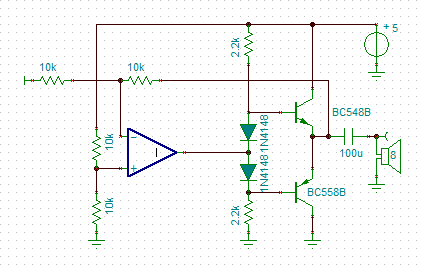
One option is to add a push-pull transistor circuit to the output:
![]()
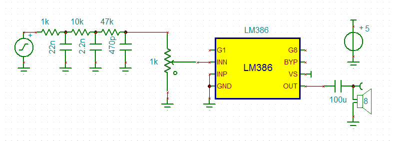
LM386
An LM386 will drive an 8 ohm speaker directly and has a 50k imput impedance, gain is programmable from 20 to 200.
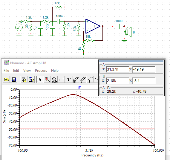
For this application, an LM386 has merit. The gain bandwidth (5Mz) and input impedance is high enough for a multi-feedback band pass. Here is a schematic of a Sallen Key band pass:
![]()
I have used an ideal OpAmp instead of the real thing as TinaTi does not have it.
The gain of the 386 has been set to x20. As the 386 has an output voltage swing of the supply voltage less 2 volts, the 5v PWM input has been attenuated for an output of 2.5 volts peak to peak. I added a 1u capacitor to the attenuator network to roll off the high frequency faster. I have not shown the zobel network or the other 386 circuity.
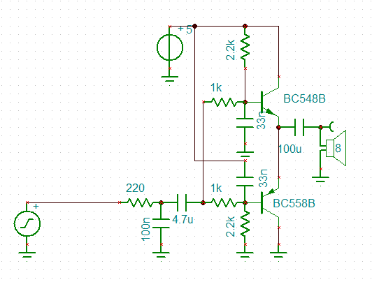
Transistors
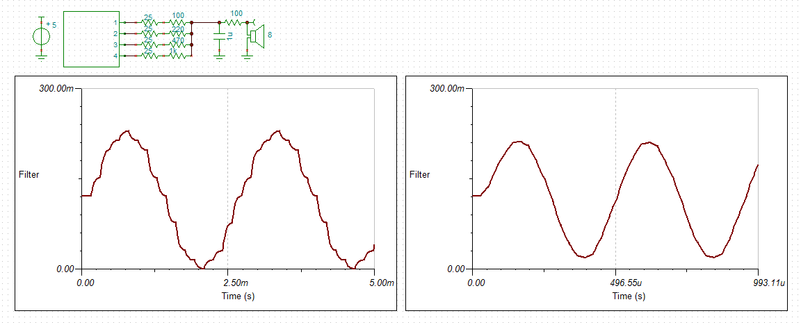
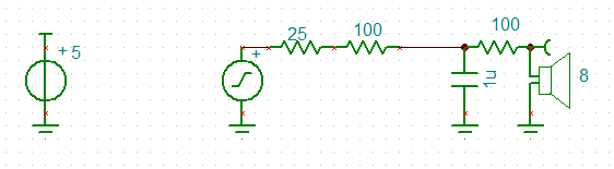
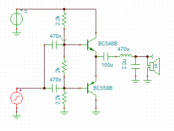
No problems, here is a narrow band speaker driver/buffer:
![]()
Note that the 25R is the atmega328p output impedance but the 100R is to limit the current to the maximum permitted.
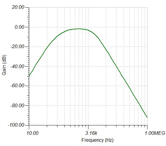
And here is the frequency response:
![]()
The buffer has a -7bB loss but the 31kHz PWM frequency is attenuated a further -28dB.
Quiescent current is about 13 mA according to the simulation.
A speaker microphone input circuit would look like this:
![]() Source: www.next.gr/uploads/51/sp_mic.gif
Source: www.next.gr/uploads/51/sp_mic.gifThis image is a common base followed by a common collector (an emitter follower). (The emitter follower is rather useless here!)
Transformers and LC Filters
Good audio transformers are bulky and expensive.
I did spend some time looking at LC impedance matching but high Q (low resistance) components are also quite bulky. I have some suitable toroids (FT-68-??) that are good to 300kHz with an Al of 1.06 uH per turn.
Here is the type of design I have looked at:
![]()
Due to impedance matching the circuit delivers x3.4 the power to the speaker than using just a 100R to limit the current. Other than the steep high frequency roll off it does not seem worth it.
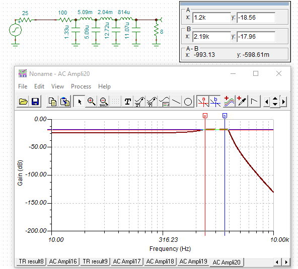
A good place to put the LC filter is on the output of the audio amp:
A 470uH toroid is just 21 turns on the above toroid. Here is the frequency response:![]()
![]()
Two Options Done
I have designed a transistor and a LM386 versions.
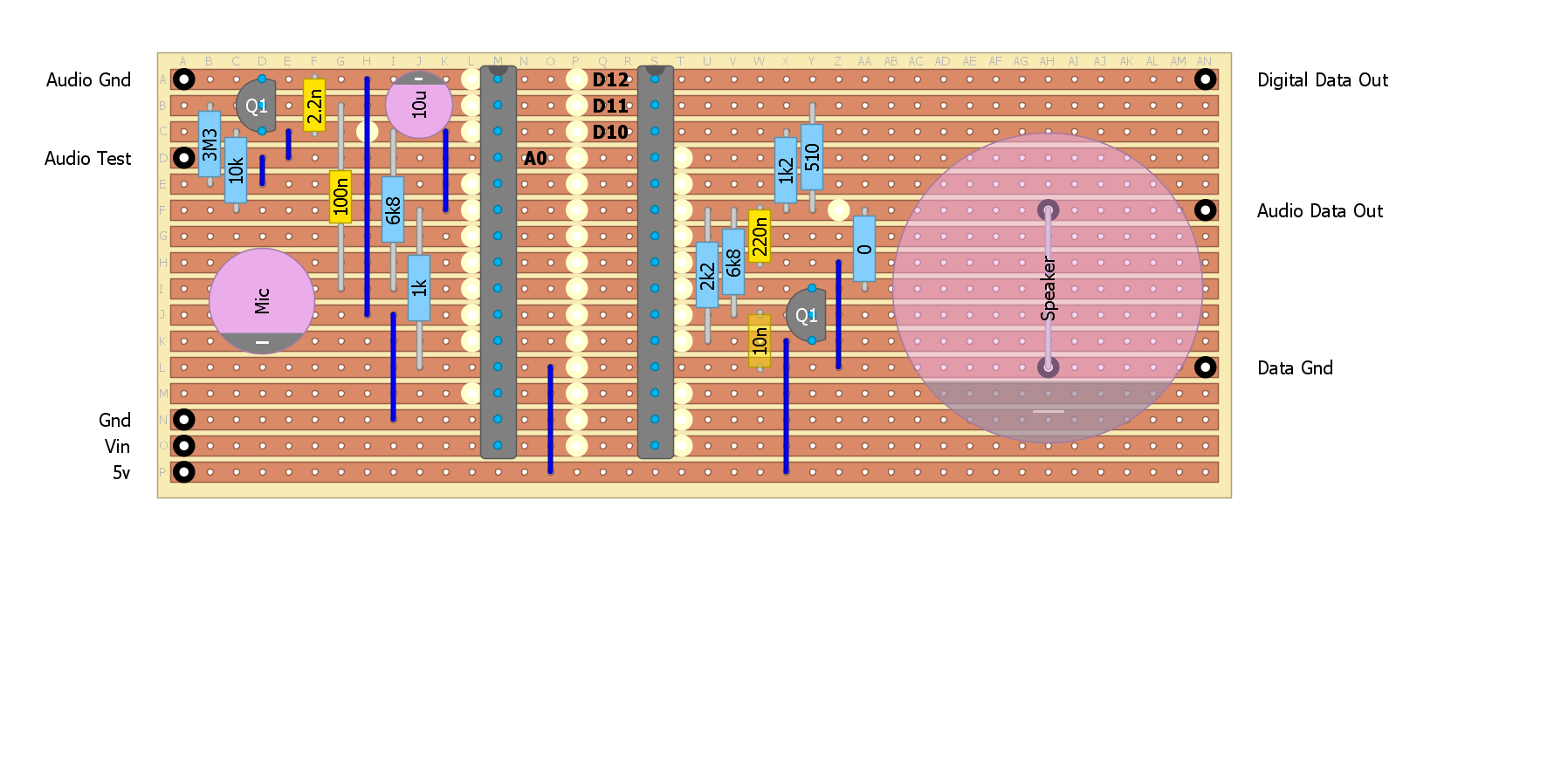
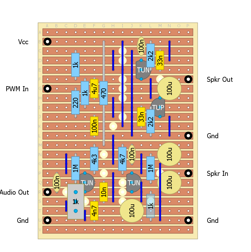
The Transistor Version
Here is the transistor version strip-board design:
![]()
Here is the final PWM buffer:
![]()
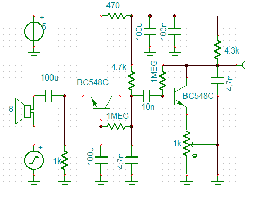
And the final pre-amp:
![]()
The problem with the transistor version is that at this level of complexity it will need to be debugged (built and tested in stages).
The LM386 Version
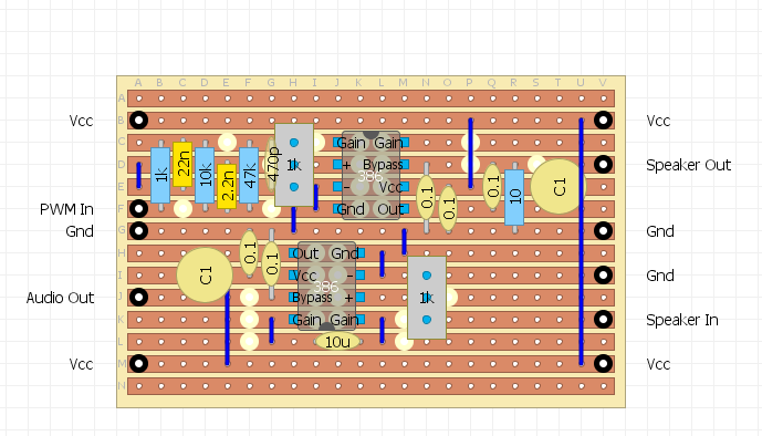
Back to the LM386 version:
![]()
Here is the PWM buffer (less the Zobel network):
Basically a three pole RC LP filter and attenuator. The output voltage is 2v pp for a 67% setting on the potentiometer. The maximum output voltage without sever distortion is about 2.2v peak to peak.![]()
The LM386 spice model came from https://hackaday.io/g4lvanix
(https://github.com/g4lvanix/Spice-models/blob/master/sub/LM386.sub), thanks.
Still Not Good Enough!
The LM386 version is at the near foolproof stage, the lesson appears to be that PWM is a "tough nut to crack".
Two thoughts:
- The power output for a an acoustic iPhone modem needs only to be a few mW rather than a max power of 75 mW available from the LM386 (except for experiments using a "loud" speaker).
- A simple resistor ladder for direct digital to analog conversion would simplify the filtering requirements (and free up a timer).
Solving the DAC Maths
To solve this problem I created a simple spreadsheet and modelled a HP RC filter and a LP RC filter.
A LP RC filter can be modelled as exponential smoothing:
- y[i] = a*y[i-1]+(1-a)*x[i]
Where:
- x[i] is the raw input at time step i
- y[i] is the filtered output at time step i
- a is a constant between 0 and 1
If T is the time step T between samples then:
- RC = T*(1-a)/a
- Flp = 1/2/Pi/RC
Similar for a HP RC filter:
y[i] = a*(x[i]-x[i-1]+y[i-1])
And:
- RC = T*a/(1-a)
- Fhp = 1/2/Pi/RC
I solved these by hand many years ago but you can find them on Wikipedia.
The centre frequency we are interested in is the geometric mean of 1200Hz and 2200Hz:
- F0=(1200*2200)^0.5
- =1625 Hz
I used the Excel Solver to minimum error squared by adjusting the HP and LP filter "a" constants. I also adjusted the duty cycle of the digital outputs. Here is the results:
![]()
I only used the last cycle was used for the error measurement.
The optimised parameters were:
- LP corner frequency: 659 Hz
- HP corner frequency: 3853 Hz
- and the digital duty (i.e. the time spent at 0 or 2): 126 degrees
The digital duty is not an important parameter and 120 degrees would be fine.
Designing the DAC Ladder
To start I modelled a simple 2R-R ladder, here are the results:
Not too bad I suppose. Perhaps I should move the centre frequency to clean up the low frequency key a bit better.![]()
Need some work to increase the output voltage and reduce the output impedance.
Here is the improved version:
![]()
All that is need is a buffer to drive the speaker.
Decimating the Design
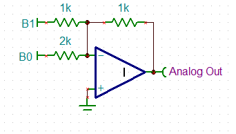
After designing the R2R ladder I thought it would be a good idea to "Decimate" the design (i.e. ruthlessly reduce the part count). So I was looking at a summing DAC like this:
![]() This can be reduced (if voltage can be sacrificed) to:
This can be reduced (if voltage can be sacrificed) to:![]()
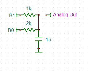
At this point I realised the bottom 1k resistor could be replaced with a capacitor:
![]()
Now that is "two birds with one stone". But what is the RC constant for this? No wantibg to do the maths:
- If we assume B1 and B2 are in phase square waves then the RC constant by inspection is R1*R2/(R1+R2)*C and the voltage gain is 1 (for low frequencies).
- If we assume B1 and B2 are out of phase square waves then the RC constant by inspection is R1*R2/(R1+R2)*C and the voltage gain is 1/2 (for low frequencies).
So neat, no complicated maths.
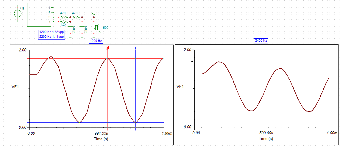
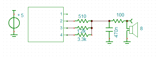
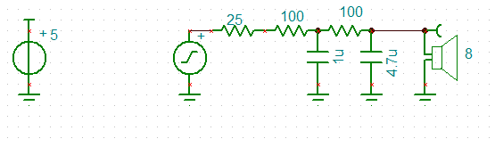
So here is my second order low pass design:
![]()
Note in selecting the RC constant I have a choice:
- select an RC constant that has similar output voltages for the mark/space frequencies as per the previous designs and accept the high frequency noise, or
- select an RC constant with minimal high frequency noise and accept different output voltages for the mark/space frequencies (the mark frequency being attenuated).
For the FSK demodulator reducing harmonics is more important than amplitude variations. Thus the RC constants used in the above schematic.
In the above schematic I have shown a 500 R speaker? Well I forgot that I originally intended to use these 35 mm diameter ceramic speaker that I have, rather than the 8 R speakers I have been battling with.
Although ceramic speakers are more efficient then the equivalent sized moving coil speaker, I suspect 1.1 to 1.7 vpp (0.3 mW to 0.7 mW) will not be loud but quite adequate for an acoustic modem.
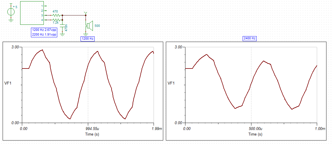
More Ruthlessness
If I drop the second low pass, I get higher speaker voltages and not unreasonable signal:
![]()
The above power outputs are 0.9 mW for 2.2 kHz and 1.8 mW for 1.2 kHz.
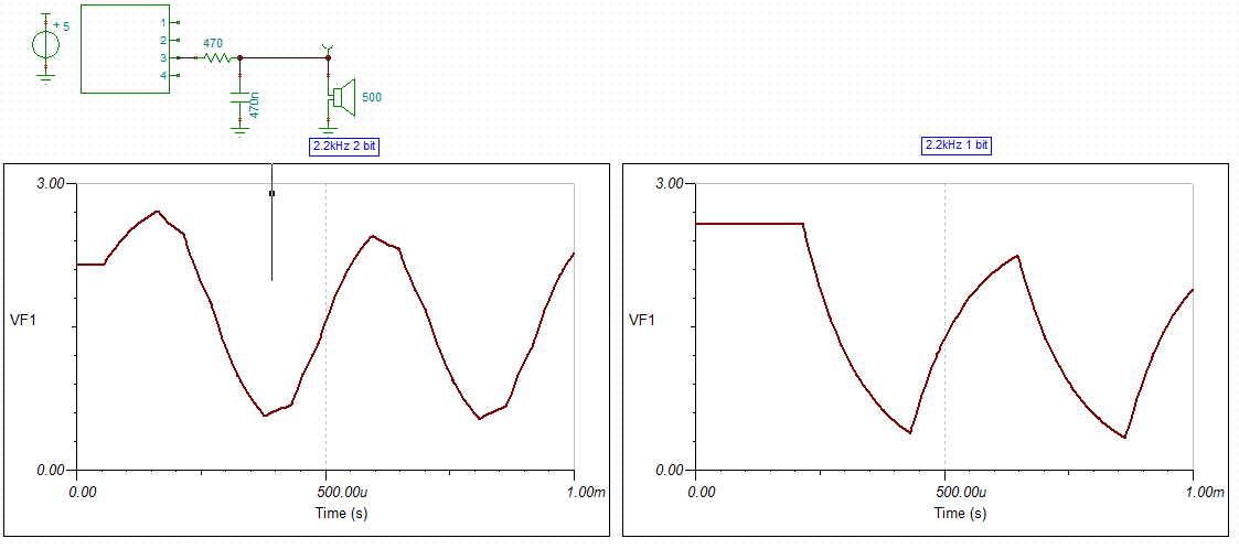
It is worth looking at how good the 2 bit summing low pass filter is:
![]()
The difference between 2 bit and 1 bit in the above image is pretty impressive!
I think the first order 2 bit DAC with the ceramic speaker should be sufficient for the application.
The datasheet for the ceramic speaker suggests that the they should not be subjected to a long term DC voltage, so a 1 uF decouple capacitor is required (not shown).
Well that was Disappointing
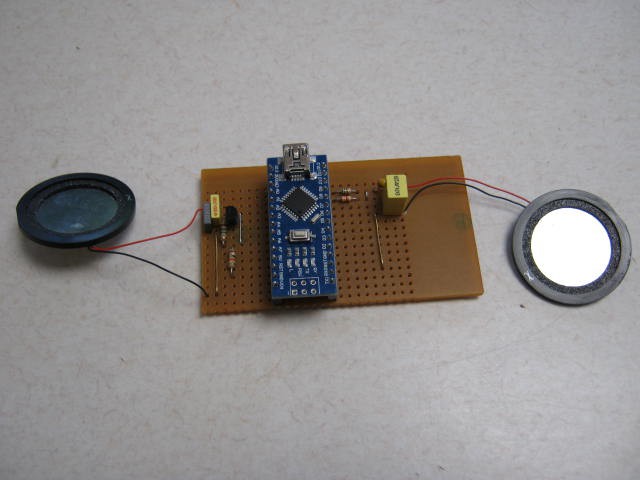
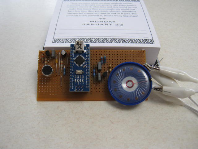
Here is the assembled modem:
![]()
First problem was that the sound level was very low. Think of a whisper (~20dB)!
Checking the wave form on the speaker, is was as expected:
- 2.5 vpp at 1200 Hz
- 1.8 vpp at 2200 Hz
That is a very bad speaker. These speakers don't match the muRata spefications (for VSB35EWH0701B). They should deliver 70 dB for 1v rms (~2.8 vpp) at 10cm. 70 dB is a vacuum cleaner at 1m!
On the input side the audio output after 40dB amplification was only a few mv. These are very bad microphones.
Basically they are going in the bin and I will buy something else. I may as well buy some proper microphones as well.
Audio Output Test
The output signal is as expected unless you send random data. Then it breaks up. it can not handle the frequency shift. So I will have to use the second low pass filter option.
Updated Second Order Low Pass Filter and Buffer
After checking what was available, I settled on a 30 mm diameter PCB mount 100 ohm speaker. The AST-030C0MR-R is rated at 80 dB at 10 cm with a 0.1 W (9 vpp) input.
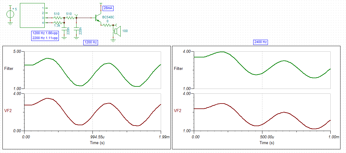
Here is the schematic:
![]()
The zero ohm resistor in series with the speaker allows the volume to to reduced as required. The emitter follower has just enough free-board for 3 vpp input.
As an experiment I used a 40 mm 8 ohm speaker with a 97 ohm resistor in series, to test the output loudness. The volume is probably about 20 dB as the power to the speaker is only about 250 uW. A little louder than the ceramic speaker but not much. With a 30 mm diameter 100 ohm speaker, the output power will be about 4 mW. This has an apparent loudness of about four times.
Watts to dB
My estimates of dB loudness are basically guesses so time to injects some science.
I found a reference that suggests a typical HiFi speaker delivers about 85 to 92 dB at 1 m. The AST-030C0MR-R is rated at 80 dB at 10 cm for 0.1 W power input, that is the same as 80 dB at 1 m for 1 W power input. A speaking voice (at 1 m) is about 60 dB. So the required input power is 100 mW from these 30 mm speakers for a speaking voice. As the input power is expected to be 4 mW (-48 dB) then the output loudness will be 32 dB. 250 uW is -72 dB so the loudness is 8 dB (n.b. 10 dB is breathing!), so my above guesses of 20 dB were way off!
For this application, the modem is relying on being less than 1 cm away from the iPhone microphone and as the iPhone is happy to be talked to from a metre away, we can add 40 dB to the 32 dB to get 72 dB so the iPhone should be able to handle it.
Modelling the Summing Capacitor
I ran a simple simulation of the summing capacitor model in Excel and got very similar optimisation results to my "eye-ball" of the Tina-TI simulations:
- Bit 1: 510 R (fixed)
- Bit 0: 1k2 instead of 1k3
The output voltages from Tina-TI are now :
- 2.38 vpp for 1200 Hz
- 1.38 vpp for 2400 Hz
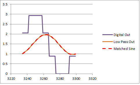
The optimisations were designed to minimise the harmonics (i.e. best sine wave for 1200 Hz) and was based on a summing DAC and a low pass filter of 1 vpp output:
![]()
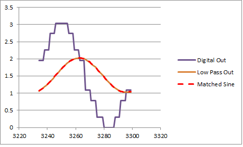
I reworked the code for a 3 bit DAC:
![]()
- Bit 2: 510 R
- Bit 1: 1k2
- Bit 0: 3k3
AlanX
An Old Fashion Acoustic Modem for the iPhone
My son recently returned from a holiday in China. His biggest complaint was the blocking of FaceBook!


 You may be able to see that the filter Q is closer to 3.6 than the design of 2.2.
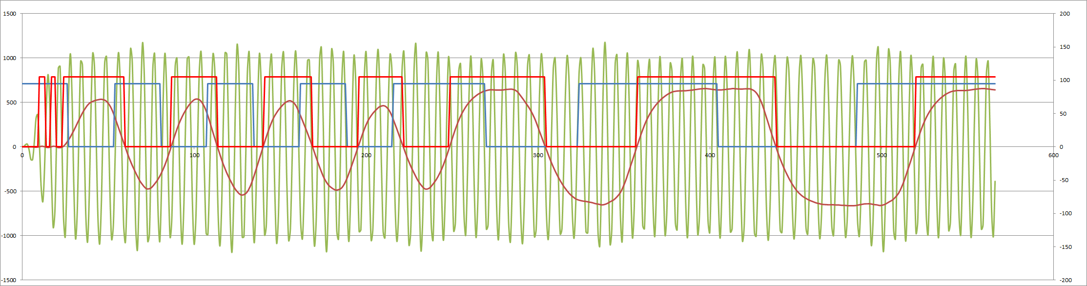
 If I change the sample frequency to 13200 Hz (from 12000 Hz) and delay to 9 (from 8), the issue disappears?
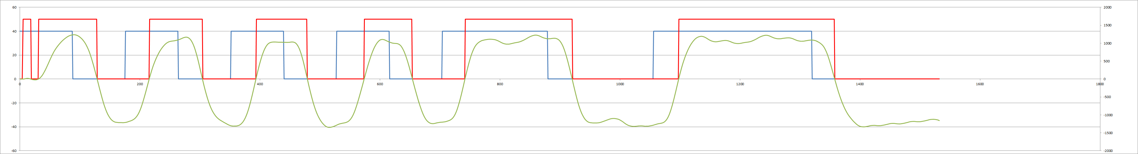


 And the answer 1200/2200 Hz:
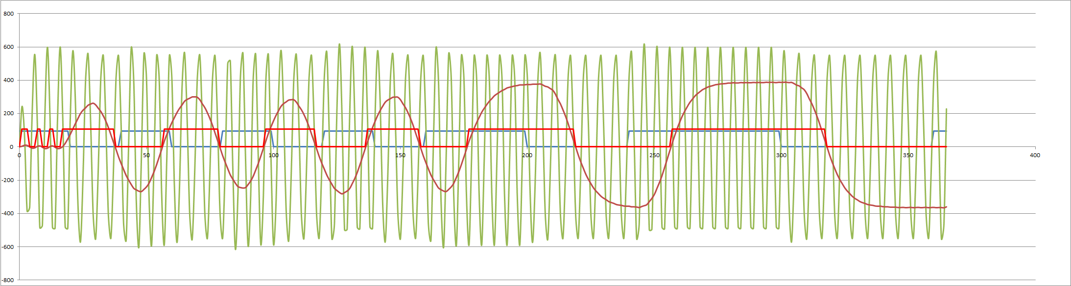


 Note that the top of the signal has less range than the bottom of the signal.
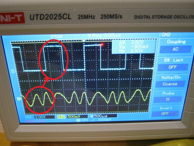


 This can be reduced (if voltage can be sacrificed) to: