 Tamas Feher
You can explore the current state of the design through a 3D visualizer.
Click this link and give it a spin!
The famous ball balancing platform reimagined
Already have an account? Log in.
To make the experience fit your profile, pick a username and tell us what interests you.
You can explore the current state of the design through a 3D visualizer.
Click this link and give it a spin!
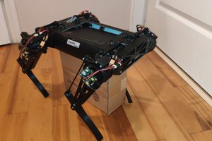
Thank you for coming along for the design and development of the BJR!
I learned a lot about coding, prototyping, sensors, and control systems during this project.
You can find the full source code of the project in this repository: https://github.com/EverydayDynamics/bjr
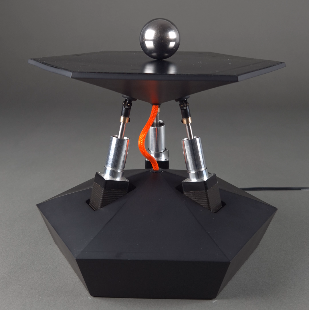
Here is a picture of the finished product:
The coated 3d printed parts came out beautiful!
My worry was that the black vinyl on top of the touchscreen would hinder it's effectiveness, but no issues found whatsoever.
Please enjoy this short video showcasing the robot in operation!
Let me know if you would like me to show how any of it's parts work, or what project I should do next.
I'm thinking about something with machine learning in it.
Cheers!
Inside the BJR_019 lives an STM32F4 microcontroller, orchestrating motion control, sensing, and communication. Every line of firmware on that chip and the supporting software that interacts with it was written in Rust.
The decision was deliberate. I believe the Rust ecosystem is mature enough to get more widespread in the embedded community. With this project I wanted to test my assumptions.
Debugging bare-metal embedded systems is always harder. Crashes rarely announce themselves with helpful stack traces. Most often, things just stop working.
With Rust, many memory-related bugs are caught before they ever touch the hardware. The compiler enforces safety rules that can feel annoyingly strict at times. In retrospective those same rules have saved me from introducing hard-to-find bugs.
Using a different language doesn't make bugs magically disappear, but even if it fails, debugging has been much simpler.
Took a little while until I got used to the HAL's design patterns, but once I got a hold of it, I could apply it to all the other projects in rust. It also gave birth to my own higher level abstraction (BAL, the Board Abstraction Layer) that I'll introduce in a later log.
The BJR_019 project isn’t just firmware. Alongside the embedded code, I wrote a telemetry visualization tool, also in Rust.
This small visualizer enabled me to chisel out control related issues with minimal data processing. I could see what's happening to the robot in real time.
Because both the firmware and the visualization software shared the same language, I could rapidly iterate on the communication protocol. Adding a new telemetry field was as simple as tweaking a few lines in one package That tight integration was a huge win for speed.
One of the standout parts of this journey has been using probe-rs. an incredible toolkit for embedded Rust. With a single-line installation, I gained:
If you're unfamiliar with Segger's Real Time Transfer (RTT) feature, you're in for a treat! Check it out here.
Calling
cargo embed --bin bjr_app --release
Will do a couple of things:
To configure this, I added a simple Embed.toml file:
[default.general]
chip = "STM32F446RETx"

[default.rtt]
enabled = true
up_channels = [
    { channel = 0, mode = "NoBlockSkip", format = "String" },
    { channel = 1, mode = "NoBlockSkip", format = "String"},
    { channel = 2, mode = "NoBlockSkip", format = "BinaryLE", socket = "127.0.0.1:8080" },
]
tabs = [
    { up_channel = 0, name = "Log" },
    { up_channel = 1, name = "Terminal" },
]
You set it once and forget it.
For me, rapid iteration is the name of the game. The faster I can flash, debug, and visualize, the faster I can tune the robot and push it forward.
Rust, combined with probe-rs, RTT and the visualizer, gave me a workflow that was fast, productive and genuinely enjoyable. It reduced friction, allowing me to focus less on plumbing and more on experimenting with the robot itself.
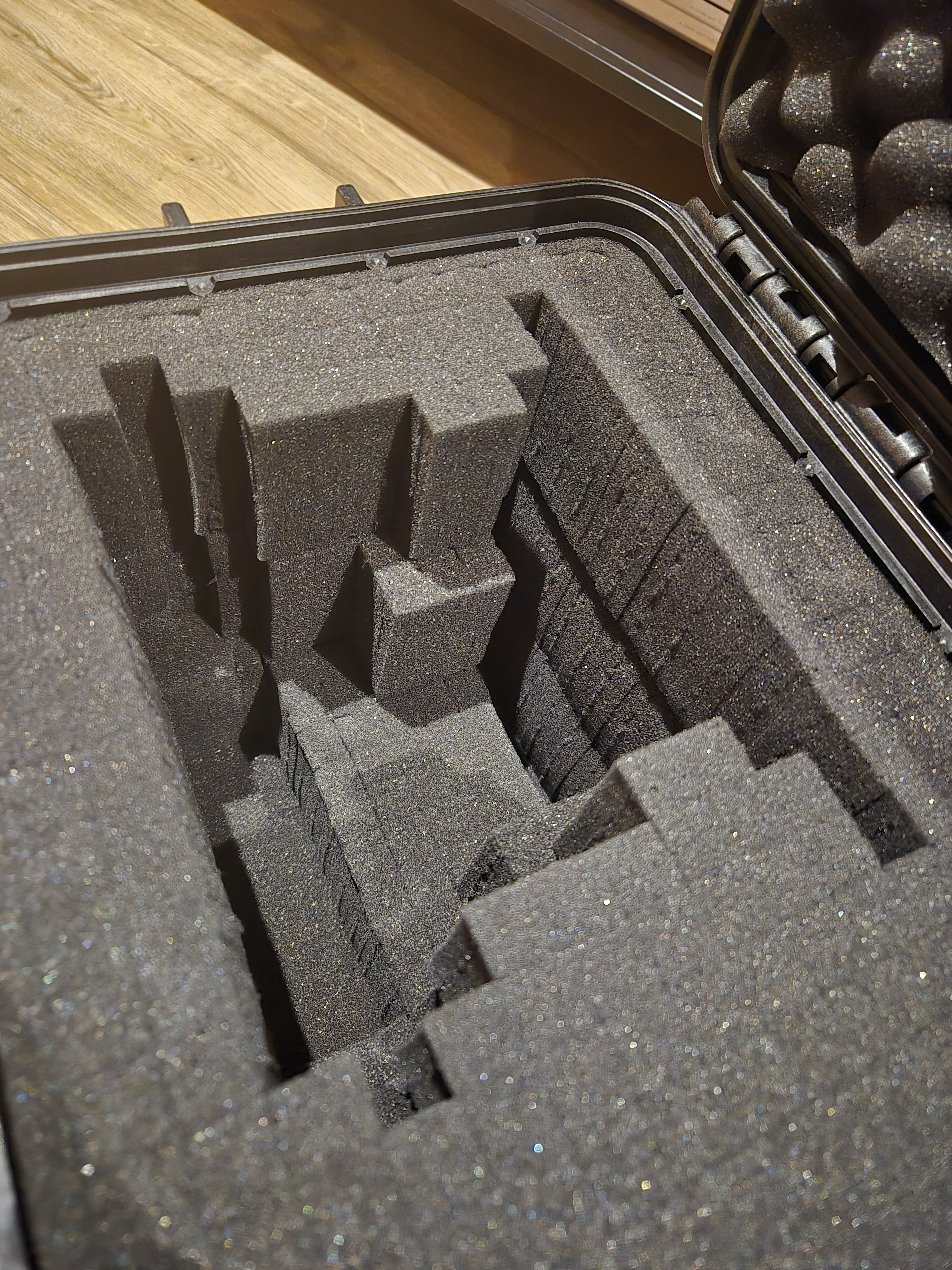
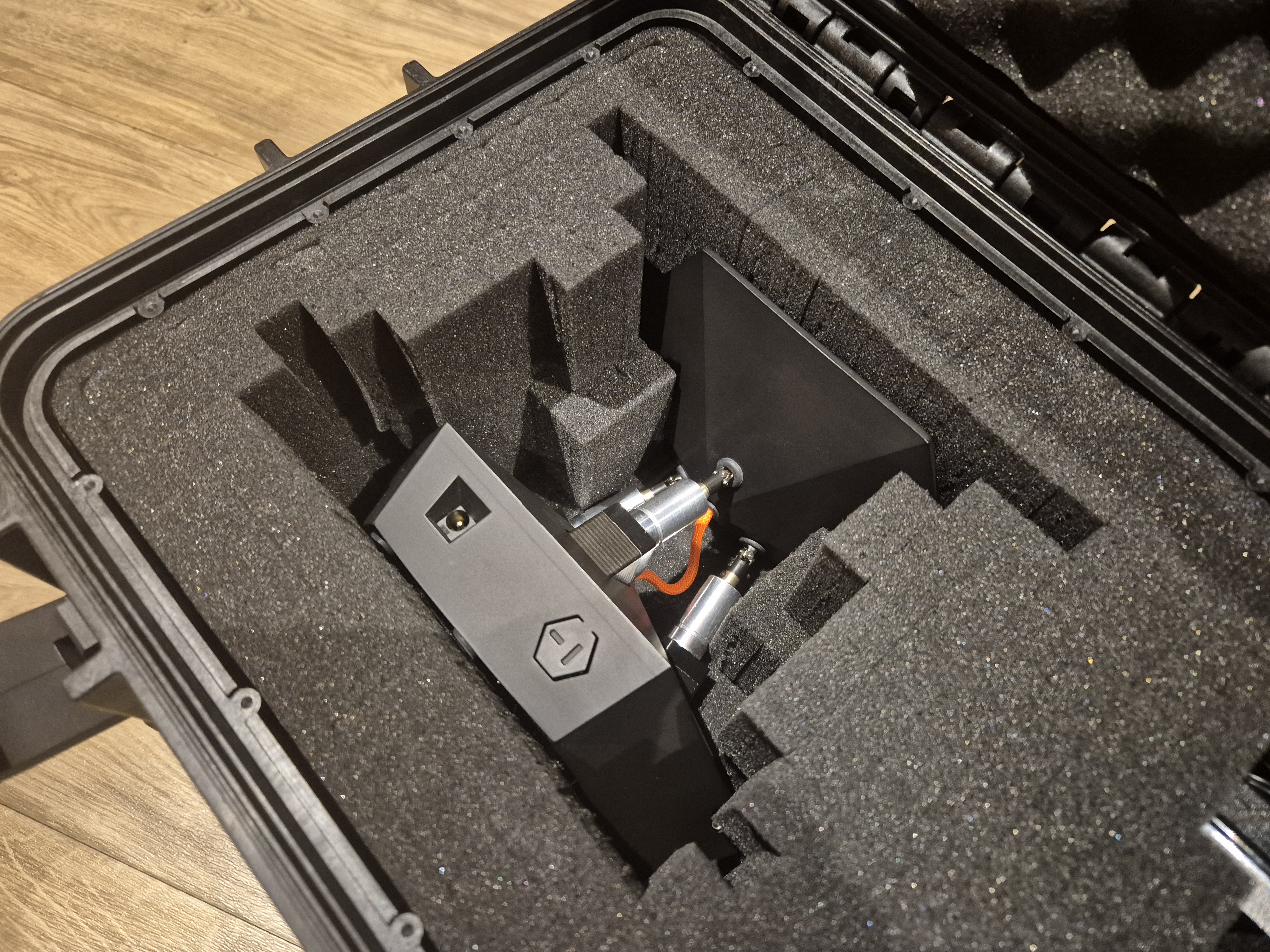
It's probably an overkill, but I've been working on this project for a long time, so I wanted to make the investment to be able to transport it without having to fear for it's safety.
The case came with multiple layers of pre cut foam cells. All I needed to do was to break away the thin bit of foam holding the chunks together, and that left me with a cavity that fits the robot perfectly.
The box is the MAX400 case. It's a tad bit bigger than what I needed, but better this way, so I can ship the accessories alongside with it.
These flight cases are no joke, it's rated for IP67, and various military standards as well.
If you find yourself having to transport your project, I can highly recommend a flight case. If not for else, the coolness factor is through the roof if you rock up to the function with one of these.
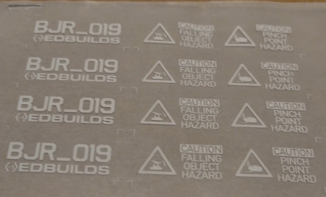
These are sort of stickers that will act as decoration and warning signs. on the robot. I chose these instead of Vinyl or water transfer, as it adds the least amount of height to the surface. (Or as I was told, I still need to test it.) I want the decals to have a low profile, so on the plate it wouldn't disrupt the movement of the ball.
The markings show:
- the corners of the active area
- The diameter of the "Circling" mode
- A cross in the center for the "Center hold" mode
- The triangles show the "Point-to-Point" mode locations.
I added the hazard labels after doing a quick risk assessment. these are the main risks that I see when anyone interacts with the robot:
- The universal joint could pinch the skin on someone's finger
- The ball could fall off from the platform, onto someones foot.
And of course, Can't forget the name and iteration of the project:
Let me know what you think of these designs! I'll post soon about how they look on the robot.
Sorry for the radio silence, in the past couple months I've been busy with getting the software ready.
I will write a couple logs about the software later, but for now, please enjoy this demonstration of the control system:
It's jittery, it's wobbly, it's loud, it's noisy, it's inaccurate, but at least it's stable!
Currently it's a simple PD controller, but more on that in a follow up log.
I'm so happy with this milestone, but we are far from being done.
After that, we might have a viable MVP!
Looking forward for the next steps, stay tuned for updates by following this project.
Please give it a like as well, to keep me encouraged to continue
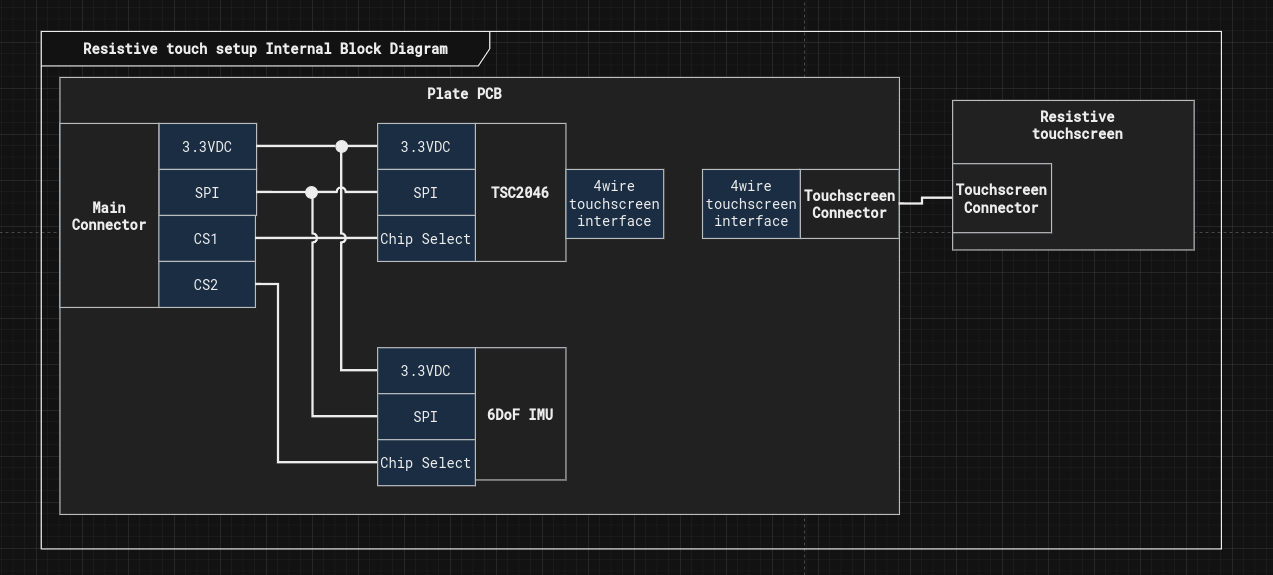
In this log we will take a look at the resistive plate PCB, see it's functionality, where it sits in the assembly, and how it was assembled. Lastly I'll go over the lessons learned.
This pcb serves 4 main functions:
1. It controls the resistive touchscreen through the TSC2046 chip
2. It serves as a strucutral support that holds the resistive touchscreen, and the adjacent elements.
3. Anchors the middle hub, which serves as the holding point of the universal joints
4. It houses a 6DoF IMU as well, to be able to tell which angle does the plate sit relative to the gravity vector.
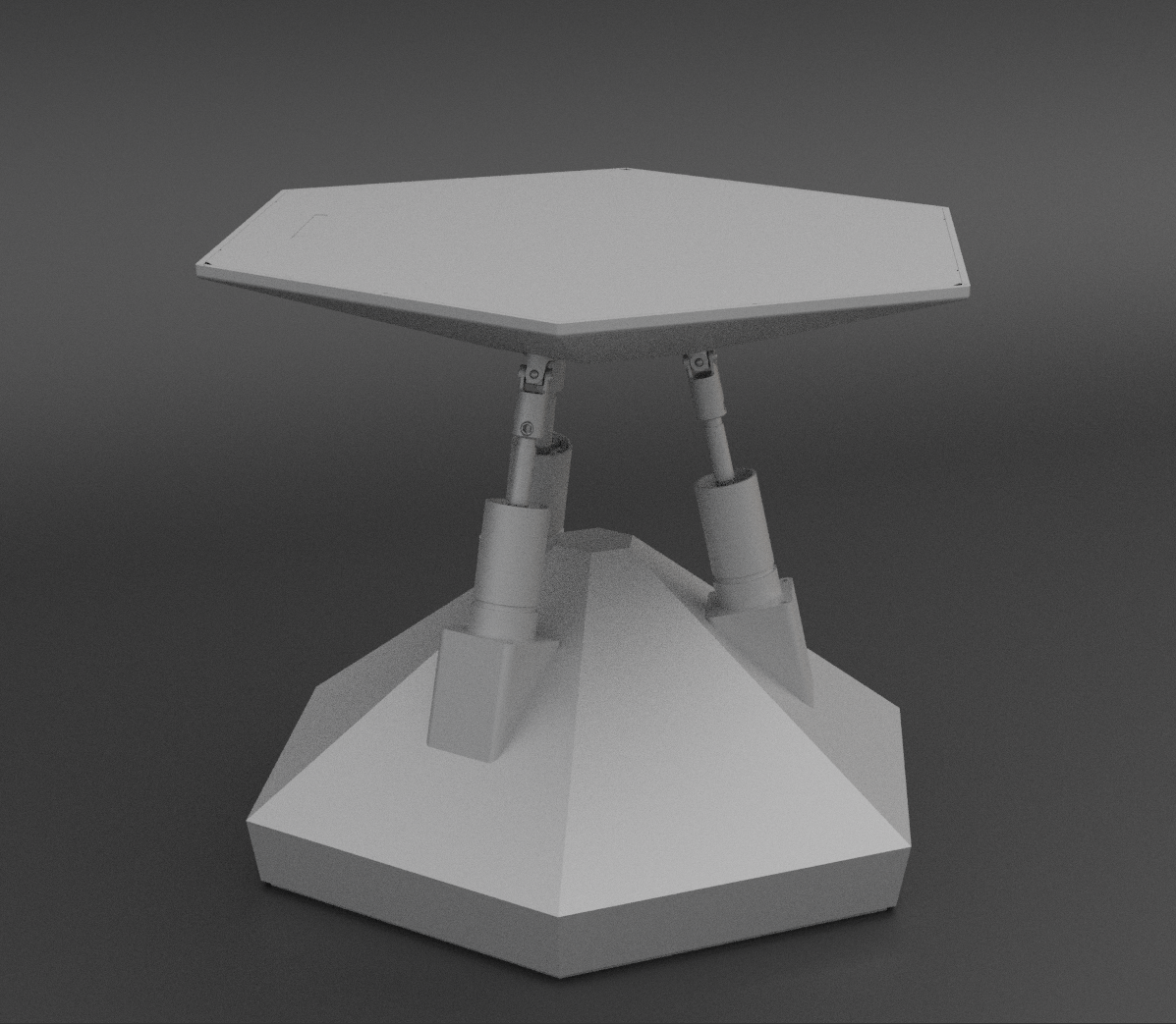
here you can see how the PCB contributes to the top assembly. (the green hexagonal part)
The chosen IMU (LSM6DS3TR-C) had a leadless package, and a very fine pitch. I didn't feel comfortable soldering it by hand, so I tried out for the first time stencil soldering. At the end it turned out better than I expected it would, however I did have to touch up the connectors by hand. I recorded the process, so please enjoy this short video of the process:
Let me know in the comments if I should improve the soldering process.
- The PCB manufacturer quotes the PCB based on size, so using the PCB as a large structural element might not been the best choice. In the future it's best to keep the PCB as small as possible, and use other material for support.
- The threaded anchors rip the copper off easily from the PCB, so I had to glue them in position, which helped at the end. It's a good lesson again not to use PCBs for structural support.
Over all the resistive plate PCB will be an important part of the build, and now I have a working prototype of it.
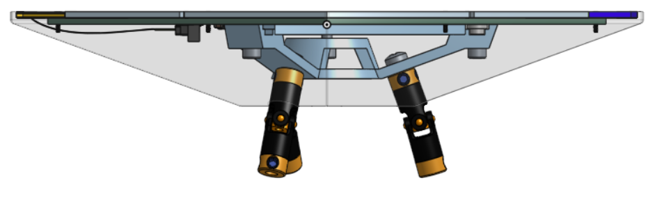
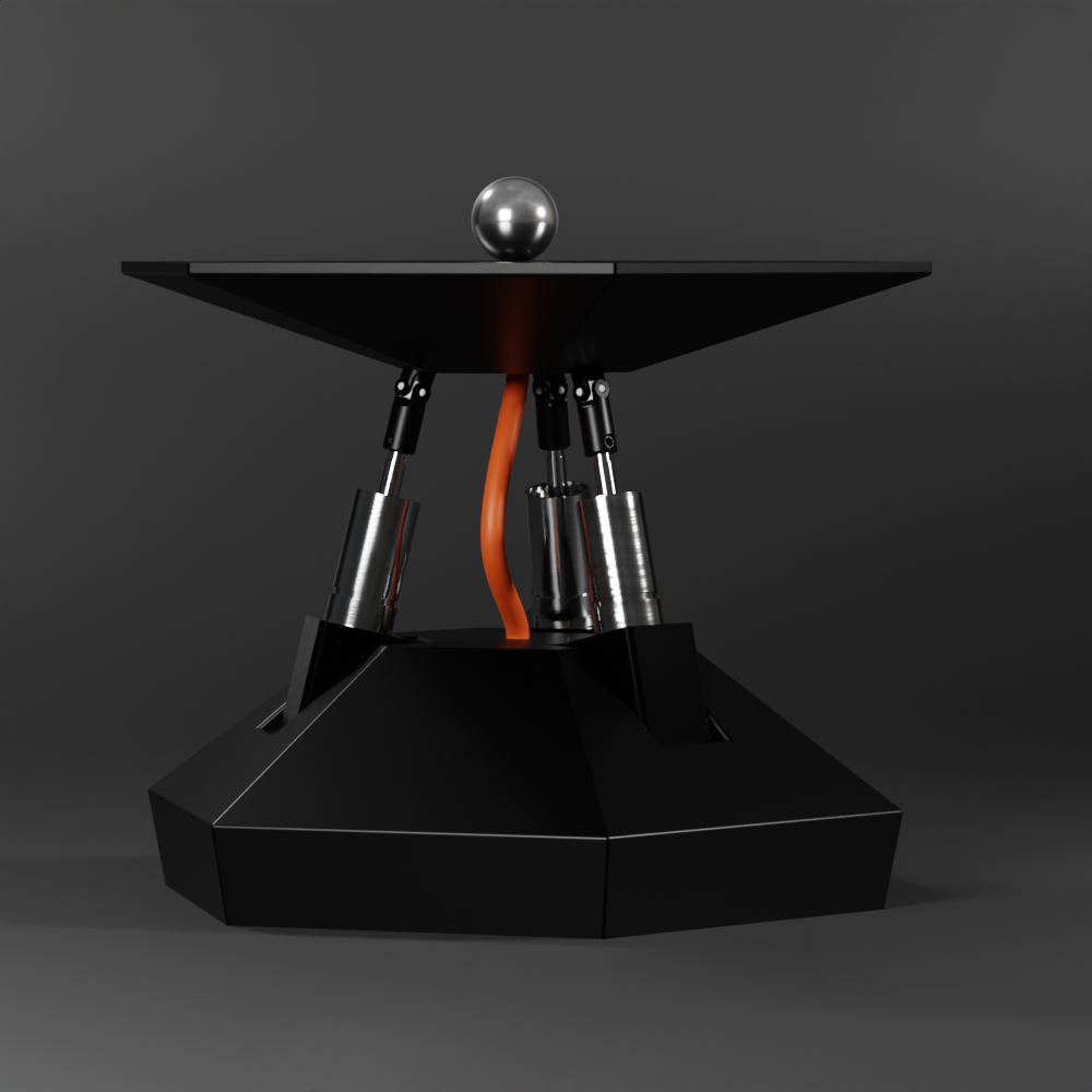
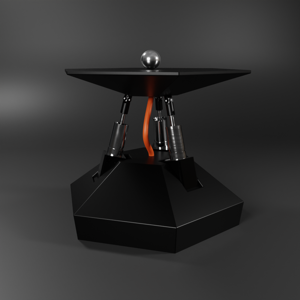
I've made a couple more renders, that elaborates more on the visual identity I envisioned for the project.
Please take a look, and tell me what you think:
The bottom and the top parts are geometric and very clean looking in terms of visual aesthetics. In the meantime the middle layer is unapologeticly exposed, celebrating the raw robotics. It exposes the universal joints, the pistons and a striking cable that flexes as the plates moves around.
The renders were done in Blender by exporting the model from onshape. Here are a couple more setups:
There are still a lot to be designed here, the cable is just a placeholder and the bottom shell is to be detailed further, but this would be the general outline.
Tell me what's your idea to improve the visual identity here.
The last log has been a couple months ago, In the meantime I moved houses and now that I'm settled in, let's get this project off the ground again. In this log I'll introduce an alternative design that uses resistive touch sensing instead of capacitive or inductive sensing.
In the earlier logs it looked like the inductive sensing would be a suitable candidate for this project, so why is it changing? you might ask.
It's true, however it takes a fair amount of design, prototyping, coding to make it into a feature that can accurately detect the ball's location. There are many other subsystems that I need to prove out. If I spend so long to get this tech off the ground, the rest of the subsystems will stay at risk.
In the industry the metric for how mature a technology is is called the Technology readiness level.
In BJR_LOG_03 I've introduced the resistive touchscreen, but just for a recap, here is how it operates:
In a resistive touch screen, there are 2 conductive films separated by a thin layer of air gap. Once something applies pressure to the top film, the contact is made by the 2 conductive surfaces. opposing edges of the films are connected to electrodes, so if a voltage is applied across them, with the contact point it forms a voltage divider. The voltage can be measured and from there the touch location can be interpreted.
The reason why I chose this over the other technologies is it's ease of use. Resistive touchscreens are available on Mouser, they are relatively cheap, and there is a wide support for controlling them. I chose the TSC2046 IC for control.
I chose rust as the main programming language for this project, simply because I enjoy writing firmware in this language. I published a driver for the TSC2046 chip on crates.io. If you ever happen to need it.
Now that the plate is not a single pcb, but rather a combination of multiple elements, I needed to redesign a little the top part of the robot. While I was at it, I thought I would give it a little personality as well.
The development continues with a resistive touchscreen as the ball detection device.
In the last log, we tried using Capacitive sensing to sense the ball, but that ultimately failed.
In this log, we are going to explore an inductive sensing method to detect the ball's position on the plate.
There are multiple ways to exploit inductance for proximity sensing. In this article, we will focus on the resonant sensing principle.
The sensing inductive coil and a capacitor are connected in parallel to form an LC tank circuit. The inherent resonant frequency of this circuit can be calculated as
As a conductive target approaches the inductive coil, eddy currents form on the surface of the conductive target. The magnetic field of these eddy currents resists the current of the inductive coil, which reduces the inductance of the system and increases the resonant sensing frequency.
Here is an example LC circuit with 2H of inductance
And the same example but with half the inductance
You can see that the frequency of resonance has changed and this is the property that we will measure in this experiment. You can find out more about the principle of operation in this
For testing, I'm using the TI LDC1614 high-resolution inductance to digital converter.
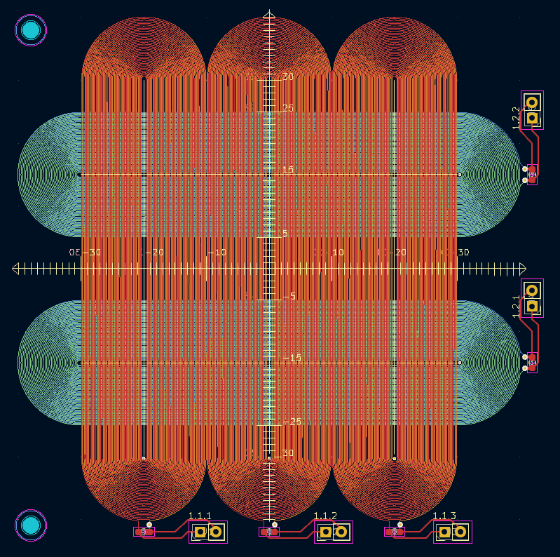
The way I chose to construct the sensing elements is by lining up multiple sensing coils next to each other. The sensing elements are spiral tracks printed on a PCB. They've been elongated into a "Horse race track" shape, so that they would be sensitive to the ball's movement only in one axis. Later tests confirmed that moving the ball alongside the racetrack doesn't influence the measurement to a significant degree.
Multiple of these tracks have been put next to each other and interlaced in different directions on a 4 layer pcb, so that we have sensing resolution in both the X and Y directions.
The final test pattern looks like a weaving pattern:
This way the vertical racetracks detect the X position by observing which coil has changed it's inductance the most. Hopefully to sub mm accuracy. Same applies to the horizontal racetracks.
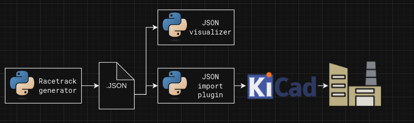
The issue with these racetracks is that there is no built in feature in KiCad (Open source electronics design software) to lay spirals out. Doing it by hand would be a grudgingly long job. Instead I opted of automating the process through python scripting.
KiCad's python scripting API is a bit difficult to use due to lack of official documentation, so I opted to offload the racetrack making into a dedicated python script, that outputs a JSON file which contains the details for all the tracks that it needs to contain. The plugin I wrote for this job takes in that json file, and imports all the primitives into KiCad. I wrote a visualizer, that enabled me to iterate on the generator without spamming KiCad with failed tracks.
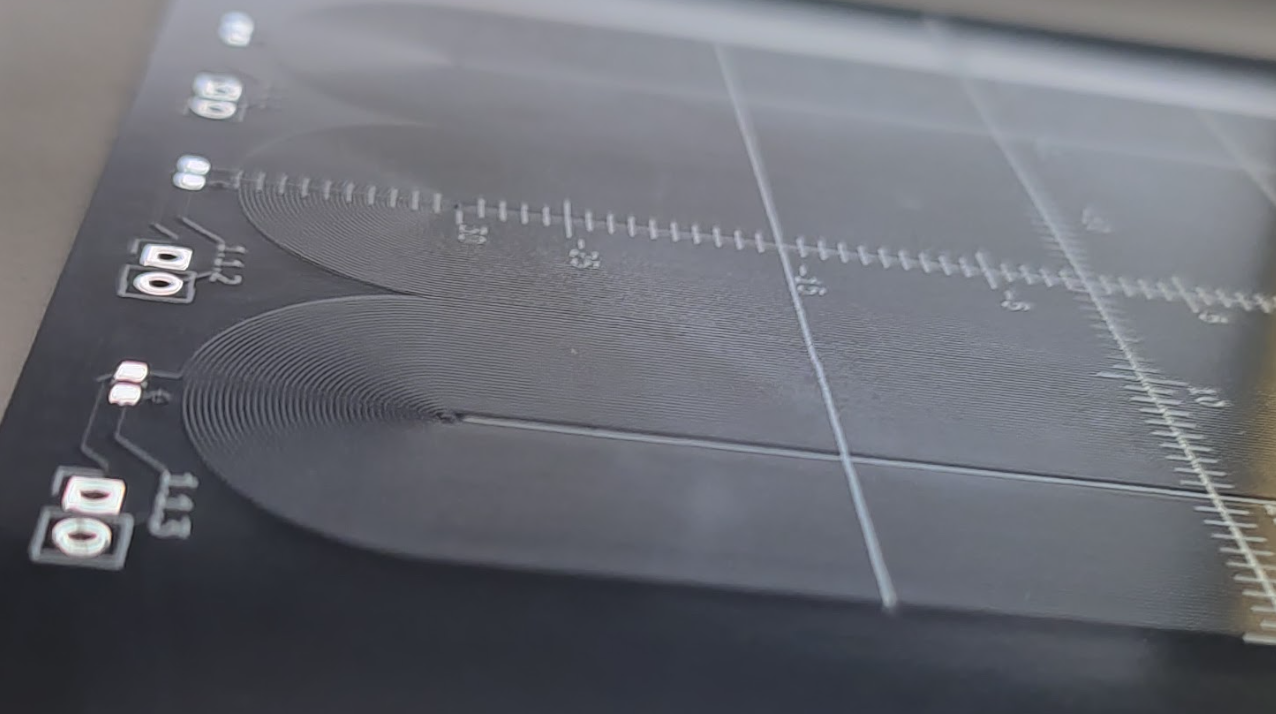
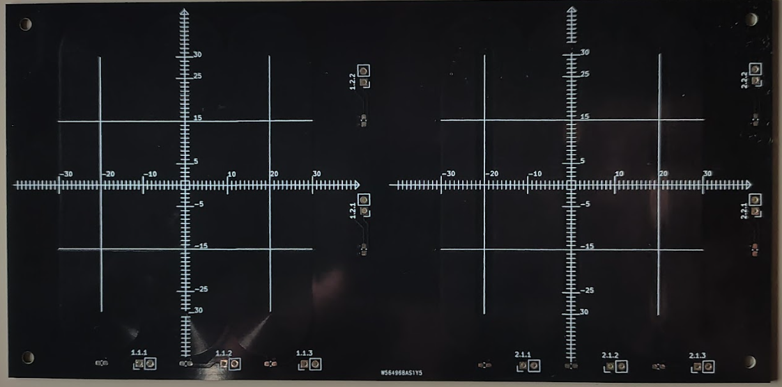
Here are the results:
The big question about this side route is if we are going to be able to make enough change in the measured inductance that we can measure it well enough? Given that we have pcb coils, interviewing traces, and spherical target, instead of a flat one.
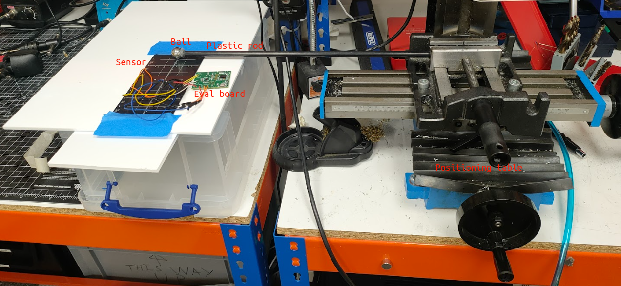
To test this I used the LDC1614EVM evaluation board and mounted the ball on a plastic rod, so it wouldn't interfere with the measurements. The plastic rod was fastened to an X-Y positioning table, that let me set the ball's position with sub mm accuracy.
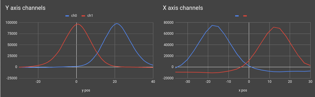
After painstakingly taking a measurement at every single millimetre and manually recording the measured value, here is what we got:
The results are promising. We are seeing a 100000 counts maximum activation on the Y axis channels, and around 75000 counts maximum activation on the X axis. With this level of resolution, i'm happy to continue exploring in this direction
In this log we've introduced inductive...
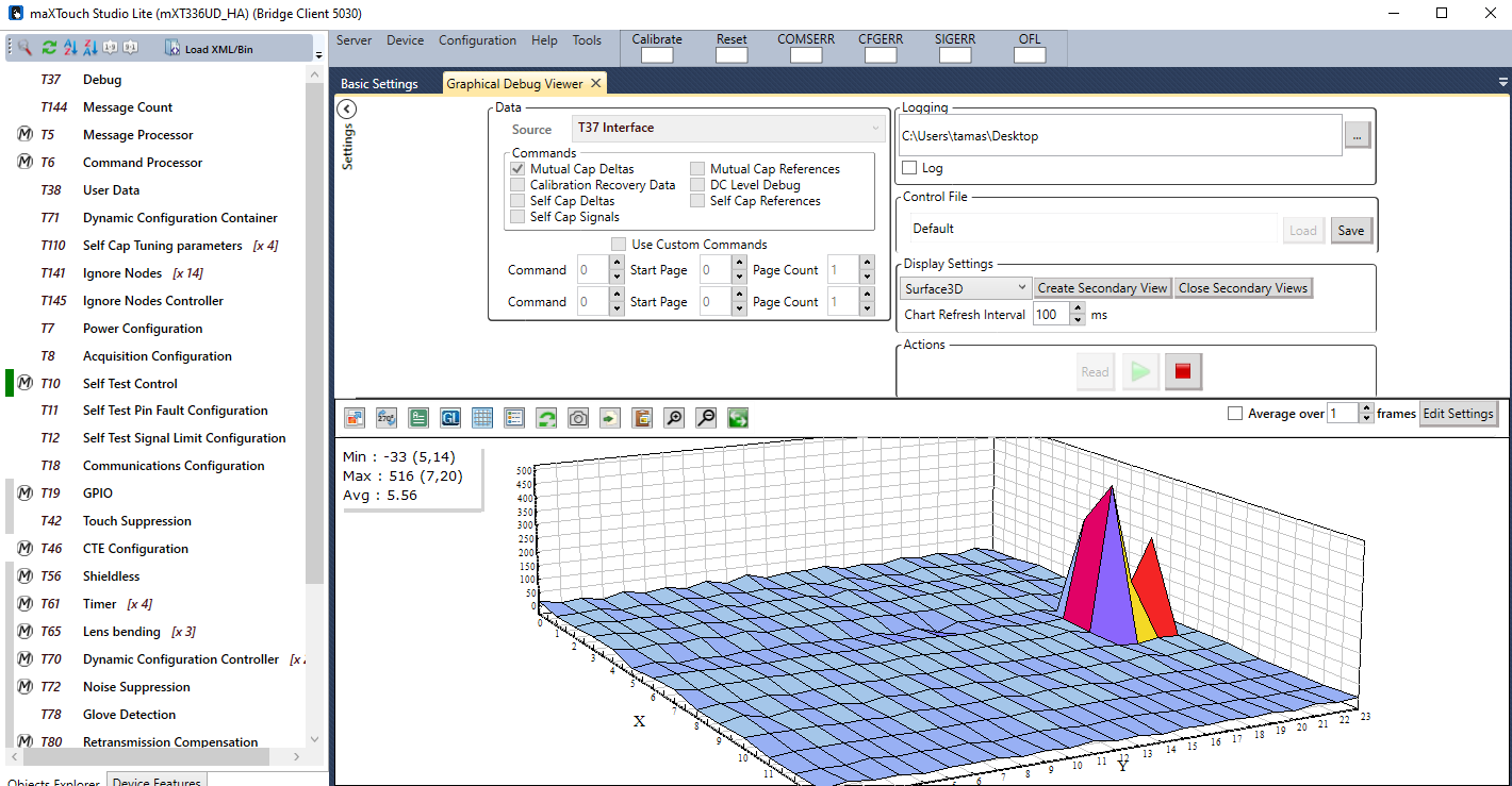
Read more »In BJR_LOG_08, we've gone through how a capacitive touch-capable PCB was designed and manufactured. In this log, we will look over how this was tested and the results of the test for use in this project.
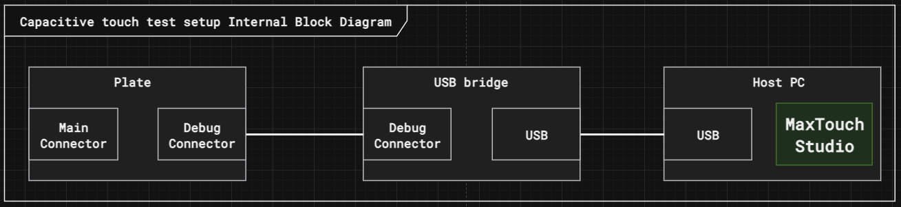
The Capacitive touch plate exposes 2 connectors. One for the main controller, which will be used in normal operation, and a debug connector designed for testing the plate.
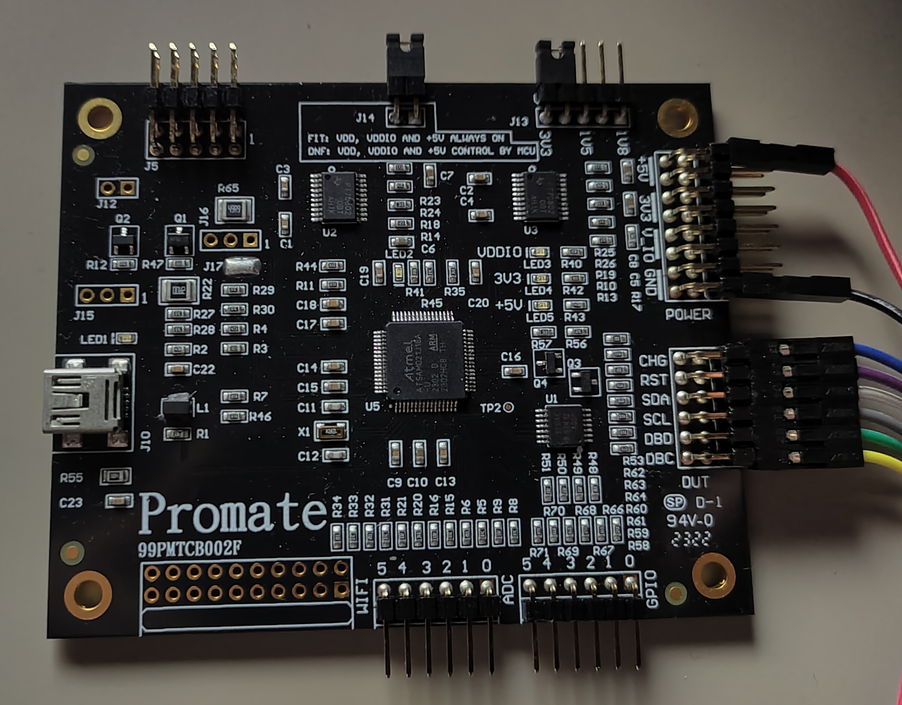
For testing, we will bypass the central controller altogether, and connect the plate to the computer through a USB bridge. The bridge is a PROMATE D21 . It's the cheapest bridge I could find at £78.22.
The reason I'm willing to spend on a device just to verify the operation of something that will be controlled through other means is the number of unknown factors. Let's say I download the I2C device driver for the MaxTouch chip, and start communicating with it through the central controller. If anything goes wrong, I have little idea whether my PCB design went wrong, my I2C bus is busted, the device driver is buggy, or my default configuration is flawed. The fewer unknown factors I expose for a test, the sooner I can conclude. By using an off-the-shelf bridge, and their tuning software, I can eliminate most of the unknown factors.
First I tested the 3.3V bus. Applying the right voltage through a test point and see if it's using the right amount of current. Then went onto the 5V source and repeated the test. Once I was confident the board wouldn't burst into flames if I connected it to the bridge I went ahead and prayed it would recognise my board. By some divine miracle, it did! No touch-ups were needed, the connection was straight-up established!
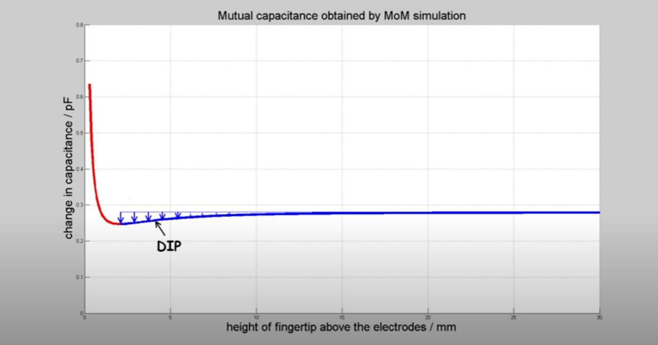
First I tested how well it detected human touch. The measurement was all over the place at the beginning. The reason for that is the mutual capacitance sensor's response to proximity. At first, the capacitance starts slowly decreasing. As the proximity reduces to near zero, the capacitance starts shooting up rapidly as seen in the graph below:
You can learn more about the physics of this phenomena in this youtube video, where I got the graph from.
The sensor only operates in the "dip" region, so to be able to detect my finger I needed to add a couple of layers of non-conducting material between the plate and my finger. (tape in my case for fine-tuning). Once the right dielectric thickness was found, the plate was working quite well to detect my finger. With a bit more work, I could have turned this into a decent touch panel.
The next video shows on a surface plot what the plate recognizes from my finger:
In the next video, you will see that the response is still great even if I hold a bearing ball in my hand.
|f I'm wearing thick gloves, there is still some response, but not strong enough to be able to detect a singular touch point, so the internal filter just gives up.
Now here comes the interesting bit. If I grab the steel ball with my gloved hand, and roll it around on the sensing surface, there is still too little activation of the sensor to pick up a touch signal.
Why is that? After looking into it I found this: It's not enough for an object to be conductive to be detected by the capacitive sensor, but also needs to be able to disrupt the electrostatic field well enough so that the capacitance change is picked up by the receiver. To disrupt the field, the object would need to be either coupled to the ground or be large enough to make a dent in the electrostatic field. Sadly the bearing ball I planned to use achieves neither. If I increase the size of the ball, the signal gets better, but with the weight limit of the actuators I can't increase it large enough to be usable. This taps into the study of tangibles on capacitive touch screens. Many have tried, but most of them came to the same conclusion: It would need a human to touch the device to be...
Read more »


Yes Rust is mature enough to use in embedded programming and brings many safety features without giving up much efficiency. I'm still need to get a round tuit to design a complex enough project for Rust.
How are you going to measure the position of the ball? Some sort of capacitive sensing?

Exactly, I'll be using the ATMXT336UD capacitive touchscreen controller. Soon I'll post a couple logs on how I got to that decision and the pcb design


 Peter Wasilewski
 AngelLM
 AdaCore
I'm curious to know more about the specific type of captive linear stepper motor you used. The options out there seem a little confusing.