Close
0%
0%

Reverse Engineering a ProMark VR Toy Drone

Notes from hacking around with a $100USD WiFi enabled QuadCopter.

Similar projects worth following
Playing with my nephew's toy drone over the holidays rationalized an after-Christmas purchase of a ProMark VR Drone for $100USD. Styled after much more expensive and capable QuadCopters, the ProMark VR Drone still delivers quite a bit of capability for that price. The plastic body is quite fragile (as I discovered), and it uses brushed DC motors, but the control system is pretty impressive. It comes with both a traditional remote control and the ability to both view a live video stream (moderately high resolution - claimed to be 720p), and to alternately control the drone via WiFi and an app running on Android or IOS. It even included a set of VR goggles to view the live video. My nephew and I had a lot of fun until I hammered it in and then it became great fodder for hacking.

The drone is comprised of the plastic body powered by a 2-cell LiPo battery (charged from a 5V input) and servo directed camera sitting underneath. The servo is a 5-wire connection (probably 2-motor, 3-pot). The camera connects via a 4-wire 3.5mm audio-jack connector and has an external WiFi antenna. The remote control is a basic unit communicating via a 2.4 GHz signal (probably something like an NRF24L01+ clone - yet to be determined). It can control the drone with traditional controls such as roll, pitch, yaw and throttle. It also provides the ability to take pictures (and store them to a micro-SD card) or start a video recording as well as initiate take-off, landing or perform a flip. The "Promark VR" app connects to the drone (camera) via WiFi and can also control flight as well as take pictures and video stored on the phone. The drone acts as the WiFi AP and the app connects to it. Of course I immediately figured there was a small Linux computer in there somewhere.

It flies reasonably well, although without any sophisticated features found on more expensive devices. They claim 300m for the remote and 100m via WiFi. Video is decent resolution but not accurate colors. They don't document the micro-SD card in the back of the camera but it will store both snapshots and video on the card if one is present.
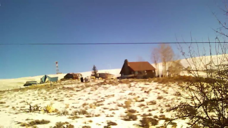
Snapshot while flying


I accidently put some run-down batteries in the transmitter and during a flight the transmitter turned off while the drone was moving quickly away. By the time I figured out the problem and was able to turn the transmitter back on, relink it to the drone and send a "land" command the drone was pretty high up and came down hard. It sheared off two landing struts and banged up the camera pretty bad. That seemed a good reason to take it apart and see how it all worked. Following are notes as I look at the various subsystems in this toy.

Some online research hints that this drone may be related, at least technology-wise, to the Syma X8WC.

Hi3518 DataSheet.pdf

Camera Module SOC specification

Adobe Portable Document Format - 11.10 MB - 01/10/2017 at 05:54

Preview

  • Laugh-out-loud shipping ingenuity

    Dan Julio01/18/2017 at 21:09 2 comments

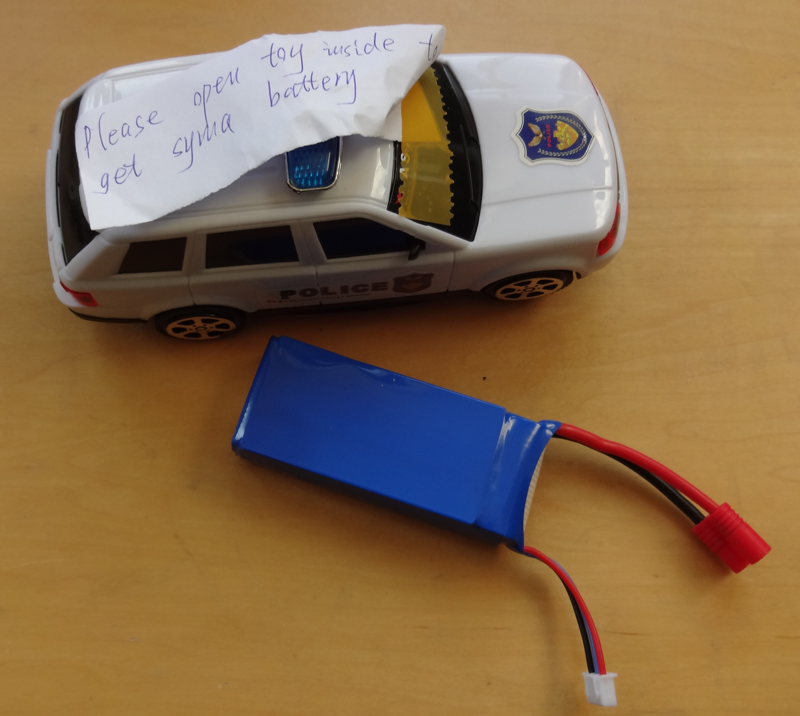
    The ProMark website listed replacement parts such as an extra battery and spare blades but no way to order them. An email to their support line went unanswered. After finding that the ProMark drone seemed to share at least a mechanical similarity to a Syma drone I went to a website carrying Syma products and ordered an extra battery and some spare blades. They arrived last night.

    The battery came packaged in a fully functional toy police car with instructions to take apart the car to get the battery. Literally just stuffed in the empty space inside the car (which motors around, making noises and blinking its LED headlights just fine on a pair of AA batteries). No doubt this is to get around shipping restrictions for LiPo batteries. I thought it was really funny and kinda clever.

  • Wireshark to the rescue / figuring out a UDP data stream

    Dan Julio01/16/2017 at 07:11 0 comments

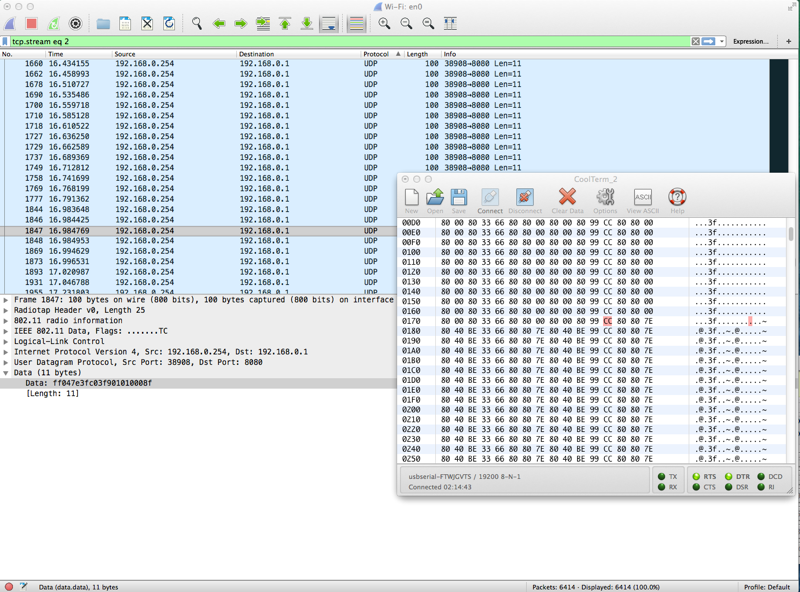
    I guessed that the phone app opened some sort of socket communication channel with the "aircraft-ctl" program running on the camera board. I figured the thing to do was to try to capture the packet stream between the camera and app and then find out the packets associated with the controls. I started with Wireshark running on my Mac with the Mac connected to the camera's WiFi network. Even though I had selected promiscuous mode, I got nothing of interest initially. I figured the Mac's WiFi interface couldn't see packets that weren't related to it's traffic. So I went looking for apps to run on the phone itself and found tPacketCapture. It looked promising and I did some experiments with it. It acts as a proxy to capture all network traffic in and out of the phone and generates a pcap file that can be viewed by Wireshark. Unfortunately it slowed down network traffic (not entirely sure why - perhaps my phone is too slow) and I ended up losing a lot of packets and couldn't really make heads or tails of the data except to suspect that the app was sending UDP packets with the control information to port 8080 on the camera (my earlier prediction of a TCP telnet-like service was wrong). But UDP made sense since the app might just stream the packets like many simple remote controls and the loss of a few packets here or there wouldn't matter (just like a traditional RF remote control). Back to the drawing board (google...) and I was able to ascertain that the WiFi interface on my Mac did, in-fact, support a monitor mode which could be enabled in Wireshark to see all WiFi traffic. I enabled it and success! I saw all communication with the camera board. Sorting on UDP packets yielded a constant stream of 11-byte packets to port 8080 whenever the app on-screen controls were enabled. Control packets seem to be sent on approximately 25 mSec intervals and simply represent the state of the controls when they are set (e.g. bits might remain set as long as an on-screen button is pressed).


    I displayed the serial data from the camera board in a CoolTerm window and then set about methodically capturing the packets as I manipulated only one control at a time. This way I could more easily associate changing data in the UDP packet with the serial data sent from the camera to the drone's controller. I ended up generating 16 different captures (my notes with some raw data analysis at the end of this log entry) and was able to figure out the basic format of the UDP packet.

    11 byte UDP packets: (about every 25 mSec)
    
      Bytes 0:1 = 0xff04 which seem constant
    
      Byte 2 = Throttle (8-bit values 0x00 - 0xFF).  Directly output in serial stream.
    
      Byte 3 = Rotate Left/Right (7-bit value 0x00 - 0x7F, center 0x3F).  Remapped around 0x80 on serial.
    
      Byte 4 = Forward/Backward pitch (7-bit value 0x80 - 0xFF, center 0xC0).  Remapped around 0x80 on serial.
    
      Byte 5 = Left/Right pitch (7-bit value 0x00 - 0x7F, center 0x3F).  Remapped around 0x80 on serial.
    
      Byte 6 = Rotate Trim (5- or 6-bit value 0x00 - 0x1F or 0x20, center 0x10).  Added or subtracted from Rotate value.  Bit 7 indicates takeoff/landing controls displayed.
    
      Byte 7 = Forward/Backward trim (6-bit value 0x20 - 0x00, center 0x10).  Added or subtracted from Forward/Backward pitch.
    
      Byte 8 = Left/Right trim (6-bit value 0x00 - 0x20, center 0x10).  Added or subtracted from Left/Right pitch.
    
      Byte 9 = Flags
    
         Bit 7: Set initially when either takeoff or landing pressed
    
         Bit 6: Set after bit 7 for takeoff
    
         Bit 5: Emergency stop (bit 7 is also set)
    
         Bit 4:
    
         Bit 3:
    
         Bit 2: Normal/Headless
    
         Bit 1:0: Speed Model
    
           00 : 30%
    
           01 : 60%
    
           10 : 100%
    
           11 : Unused
    
      Byte 10: Checksum (added to bytes 1-9 = 0xFF)

    Questions remain about the header byte values. Is that a fixed value or could different header bytes (especially byte 1 : 0x04 - since it is included in the Checksum) have additional packet information? What, if anything, do the unused bits in the trim bytes and flag byte mean?


    Most UDP data was directly mapped (potentially...

    Read more »

  • Comm protocol between camera and drone controller

    Dan Julio01/12/2017 at 03:31 1 comment

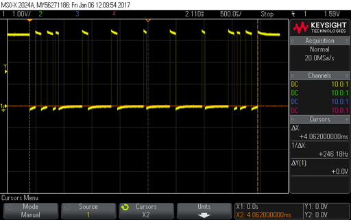
    Initially I thought the data stream from the camera board to the quadcopter controller was PPM. This signal is only active when the app is running and the on-screen controls are brought up. The quadcopter has to be power-cycled in order to be controlled by the RF remote again. However a closer look at the signal as the on-screen controls were manipulated hinted that it was a serial stream instead. This makes some sense. The HI3518 has two serial ports and it would certainly be easier to ship a set of bytes of a serial port than generate a PPM data stream. A complete frame, shown below, takes about 4.06 mSec.

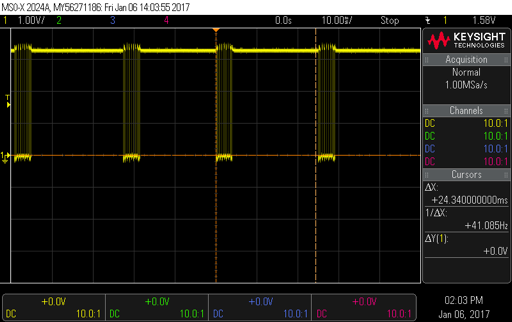
    The period between frames is about 25 mSec although it seemed to vary a bit.
    The smallest "bit" period in the frame is about 52 uSec which implies a bit rate of 19,200 baud and an 8-byte packet. Sure enough connecting the signal to the USB serial converter and a 19.2 kBaud 8N1 terminal connection yielded what looked like good data. Even better data seemed to be byte aligned and I saw direct changes when I manipulated the on-screen controls. What follows are the notes I took while associating data with control action. At the end is my guess as to what each byte means. The trim controls simply seem to add a small + or - offset to the actual control value. The start-byte and end-byte sum to 0xFF and the remaining bytes are protected by a XOR checksum.
    Some bytes were repeated while the control was being touched. I am wondering now if the application just opens a simple telnet-like port connection with the camera board (perhaps on port 8080) and sends these bytes straight through (ala a remote serial connection). Next up will be to try to suss out the network traffic between the application and camera board.

    Upon boot: ???
    
      FF 69 6E 69 74 20 6F 6B 0A CC 80 80 00 80 00 80 33 66…
    
    Upon app connection: ???
    
      66 80 80 00 80 00 80 99
    
    Upon app controls:
    
      CC 80 80 00 80 00 80 33 66 80 80 00 80 00 80 99  (repeated)
    
    Launch:
    
      CC 80 80 7E 80 40 BE 33 66 80 80 7E 80 40 BE 99  (repeated when takeoff/land displayed)
    
      CC 80 80 7E 80 42 BC 33 66 80 80 7E 80 42 BC 99  (repeated 6 times when takeoff pressed)
    
      CC 80 80 7E 80 41 BF 33 66 80 80 7E 80 41 BF 99  (repeated 59 times - maybe while press)
    
      CC 80 80 7E 80 40 BE 33 66 80 80 7E 80 40 BE 99
    
    Land:
    
      CC 80 80 7E 80 40 BE 33 66 80 80 7E 80 40 BE 99
    
      CC 80 80 7E 80 42 BC 33 66 80 80 7E 80 42 BC 99  (repeated 62 times - maybe while press)
    
      CC 80 80 00 80 00 80 33 66 80 80 00 80 00 80 99  (repeated after controls removed)
    
    Throttle up:
    
      CC 80 80 00 80 00 80 33 66 80 80 00 80 00 80 99
    
      CC 80 80 26 80 00 A6 33 66 80 80 2E 80 00 AE 99
    
      CC 80 80 44 80 00 C4 33 66 80 80 4E 80 00 CE 99
    
      CC 80 80 64 80 00 E4 33 66 80 80 7E 80 00 FE 99
    
      CC 80 80 86 80 00 06 33 66 80 80 96 80 00 16 99
    
      CC 80 80 A0 80 00 20 33 66 80 80 B2 80 00 32 99
    
      CC 80 80 B8 80 00 38 33 66 80 80 C8 80 00 48 99
    
      CC 80 80 D0 80 00 50 33 66 80 80 D4 80 00 54 99
    
      CC 80 80 DC 80 00 5C 33 66 80 80 E0 80 00 60 99
    
      CC 80 80 EA 80 00 6A 33 66 80 80 EE 80 00 6E 99
    
      CC 80 80 F6 80 00 76 33 66 80 80 F8 80 00 78 99
    
      CC 80 80 FC 80 00 7C 33 66 80 80 FC 80 00 7C 99
    
    Throttle left/right:
    
      CC 80 80 78 80 00 F8 33 66 80 80 78 C0 00 B8 99
    
      CC 80 80 78 C0 00 B8 33 66 80 80 78 C2 00 BA 99
    
    …
    
      CC 80 80 86 E6 00 60 33 66 80 80 88 E4 00 6C 99 (max right although real max seems FC)
    
    …
    
      CC 80 80 74 01 00 75 33 66 80 80 74 01 00 75 99 (min left)
    
    Right Stick up/down:
    
      CC 8B BD 88 80 00 3E 33 66 8B BB 88 80 00 38 99 (up)
    
      CC 80 41 88 80 00 C9 33 66 80 41 88 80 00 C9 99 (down)
    
    Right Stick left/right:
    
      CC AE 74 00 80 00 5A 33 66 B5 74 00 80 00 41 99 (right)
    
      CC 53 80 00 80 00 53 33 66 53 80 00 80 00 53 99 (left)
    
    Normal/Headless button:
    
      CC 80 80 00 80 20 A0 33 66 80 80 00 80 20 A0 99
    
    Right Trim Throttle twice (from center):
    
      CC 80 80 00 82 00 82 33 66 80 80 00 82 00 82 99
    
    Left Trim Throttle once (from center):
    
      CC 80 80 00 7F 00 7F 33 66 80 80 00 7F 00 7F 99
    
      CC 80 80 00 75 00 75 33 66 80 80 00 75 00 75 99  (left a bunch)
    
    Right Trim Right...
    Read more »

  • Connecting to Linux

    Dan Julio01/10/2017 at 06:42 0 comments

    The Android app "Fing" provided a list of the services available on the Linux camera ports (one could have used nmap on a computer):

    • 23 telnet
    • 80 http
    • 554 rtsp
    • 8080 http-proxy

    Telnetting to the device from my Mac gave me a login prompt but as I described in the previous post, there was no login possible because no users are enabled.

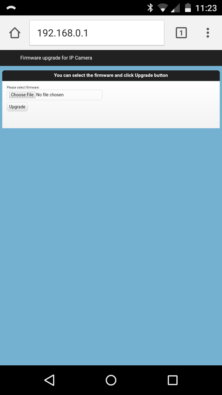
    The HTTP server helpfully serves up a simple page designed to load new firmware (which there appears, currently, to be none - in fact the ProMark website is strange. It exists but things like the pages to order replacement parts like propellers and batteries have no prices or links to actually buy anything - which makes one wonder if the company really still exists...or only existed for one Christmas season).


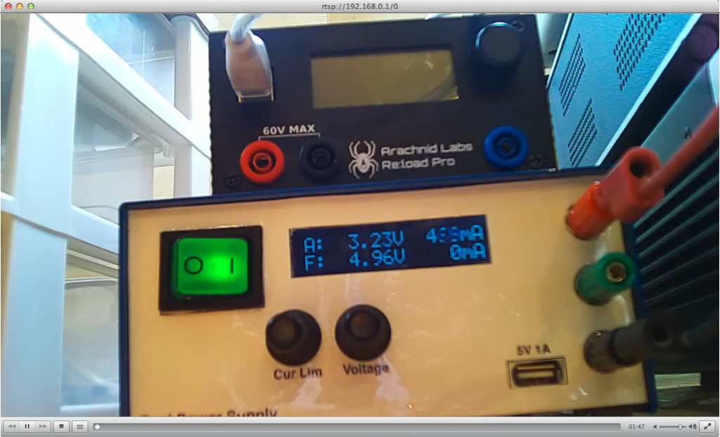
    I could get nothing at the 8080 port but was more interested to see if I could find a way to stream video from the board. Many, many hours later I was able to figure out the following way to watch real-time video using VLC. The intermediate time was spent with Wireshark watching packets on my Mac between the board and my android phone and *a lot* of googling. A hint from the wireshark log agreed with Fing that there was a RTSP video stream.

    rtsp://192.168.0.1:554/0 RTSP/1.0\r\n
    URL rtsp://192.168.0.1/0/track1

    So finally I was able to watch the camera's output in VLC with the following URL for VLC (it seems so simple written here, but there were hours of my befuddled thinking before....):

    rtsp://192.168.0.1/0
    

  • UBoot experiments

    Dan Julio01/10/2017 at 05:52 0 comments

    ProMark helpfully left a second's worth of delay in UBoot before staring the boot process available on the serial port. This meant I could get a UBoot prompt and output the machine's environment variables which show some interesting information (the output of "printenv" shown at the end of this post). It also meant I could try to boot into a single-user prompt which I was ultimately able too after a bunch of experimenting and a friend's helpful suggestion to watch some master's manipulation of UBoot on youtube. The trick for this device is to set "flashargs" as shown below to boot into /bin/sh.

    setenv flashargs ‘run commonargs; set bootargs ${bootargs} root=${flashroot} rootfstype=${flashrootfstype} noinitrd init=/bin/sh’
    
    boot


    I also changed the boot delay to 3 seconds to make it easier to interrupt the boot process (which is simply sending some character via the console serial port). "saveenv" writes the changes permanently to the flash memory (as opposed to the change I made above to flashargs which does not persevere over a power-cycle).

    setenv bootdelay 3
    saveenv

    The system uses busybox to provide most functions including "cat". I took a look at /etc/passwd from the single-user prompt and was disappointed. The system allows no logins, whatsoever, even though it allows a telnet connection and provides a login on the serial port. Score one for the security conscious developers at ProMark. Here's the contents of the /etc/passwd file from the single-user prompt (all the way from setting the UBoot environment variable "flashargs" through the boot and cat of /etc/passwd):

    ipcam # setenv flashargs 'run commonargs; set bootargs ${bootargs} root=${flashroot} rootfstype=${flashrootfstype} noinitrd init=/bin/sh'
    
    ipcam # printenv flashargs
    
    flashargs=run commonargs; set bootargs ${bootargs} root=${flashroot} rootfstype=${flashrootfstype} noinitrd init=/bin/sh
    
    ipcam # boot
    
    Booting from SPI Flash...
    
    8192 KiB hi_sfc at 0:0 is now current device
    
    ## Booting kernel from Legacy Image at 81000000 ...
    
       Image Name:   Linux-3.0.8
    
       Image Type:   ARM Linux Kernel Image (uncompressed)
    
       Data Size:    1723048 Bytes = 1.6 MiB
    
       Load Address: 80008000
    
       Entry Point:  80008000
    
       Loading Kernel Image ... OK
    
    OK
    
    Starting kernel ...
    
    Uncompressing Linux... done, booting the kernel.
    
    Linux version 3.0.8 (root@hiber) (gcc version 5.2.0 (Buildroot 2015.11.1) ) #4 Thu Aug 25 05:42:37 EDT 2016
    
    CPU: ARM926EJ-S [41069265] revision 5 (ARMv5TEJ), cr=00053177
    
    CPU: VIVT data cache, VIVT instruction cache
    
    Machine: hi3518
    
    Memory policy: ECC disabled, Data cache writeback
    
    AXI bus clock 200000000.
    
    Built 1 zonelists in Zone order, mobility grouping on.  Total pages: 10160
    
    Kernel command line: mem=40M mmz=24M console=ttyAMA0,115200n8 mtdparts=hi_sfc:512k(uboot)ro,256k(uboot-env),256k(mfd),3m(kernel),4m(rootfs) hieth.mdioifu=1 hieth.mdioifd=1 hieth.phyaddru=0 hieth.phyaddrd=1 root=/dev/mtdblock4 rootfstype=squashfs,jffs2 noinitrd init=/bin/sh
    
    PID hash table entries: 256 (order: -2, 1024 bytes)
    
    Dentry cache hash table entries: 8192 (order: 3, 32768 bytes)
    
    Inode-cache hash table entries: 4096 (order: 2, 16384 bytes)
    
    Memory: 40MB = 40MB total
    
    Memory: 35852k/35852k available, 5108k reserved, 0K highmem
    
    Virtual kernel memory layout:
    
        vector  : 0xffff0000 - 0xffff1000   (   4 kB)
    
        fixmap  : 0xfff00000 - 0xfffe0000   ( 896 kB)
    
        DMA     : 0xffc00000 - 0xffe00000   (   2 MB)
    
        vmalloc : 0xc3000000 - 0xfe000000   ( 944 MB)
    
        lowmem  : 0xc0000000 - 0xc2800000   (  40 MB)
    
        modules : 0xbf000000 - 0xc0000000   (  16 MB)
    
          .init : 0xc0008000 - 0xc0027000   ( 124 kB)
    
          .text : 0xc0027000 - 0xc044b000   (4240 kB)
    
          .data : 0xc044c000 - 0xc047d740   ( 198 kB)
    
           .bss : 0xc047d764 - 0xc0496d70   ( 102 kB)
    
    SLUB: Genslabs=13, HWalign=32, Order=0-3, MinObjects=0, CPUs=1, Nodes=1
    
    NR_IRQS:128 nr_irqs:128 128
    
    sched_clock: 32 bits at 100MHz, resolution 10ns, wraps every 42949ms
    
    Calibrating delay loop... 218.72 BogoMIPS (lpj=1093632)
    
    pid_max: default: 32768 minimum: 301
    
    Mount-cache hash table entries: 512
    
    CPU: Testing...
    Read more »

  • Linux in a toy

    Dan Julio01/10/2017 at 04:52 0 comments

    The first part of the drone I took apart was the camera. It is a complete linux machine based on the HiSilicon HI3518 ARM SOC that usually finds a home in Web Cams along with a USB-connected WiFi module and a 4-wire connection to the Drone itself. It was fairly easy to figure out that two wires were power (GND and 3.3 volts), one wire was a GPIO trigger from the drone (via it's dedicated remote control to take a picture or start a video) and one wire was control data from the app to control the drone itself. I initially assumed that data was traditional PPM but later analysis showed it was a serial stream. I found two test points which I correctly surmised where a serial port was was rewarded with 115,200 baud 8N1 goodness when they were connected to a 3.3V FTDI 230X USB-serial interface.

    USB UART connected

    It seems that this board is essentially a web-cam with an additional process added to allow it to control a quad-copter. It seems that this chip is used in a lot of "cheap" web-cams that have lots of potential exploits including hardwired login credentials. I found lists of username/password combinations online that various security researchers had found on a lot of products. I tried them all without any success. It turns out that the ProMark people are a little more security conscious but I didn't know that at this point in the reverse engineering process.

    Interesting aside: The board runs at between 300-400 mA at 3.3V when no-one is connected. It takes around 500 mA when someone is connected and above 600 mA when streaming video.

    U-Boot 2010.06 (Jul 26 2016 - 01:40:47)
    
    Check spi flash controller v350... Found
    
    Spi(cs1) ID: 0xEF 0x40 0x17 0x00 0x00 0x00
    
    Spi(cs1): Block:64KB Chip:8MB Name:"W25Q64FV"
    
    In:    serial
    
    Out:   serial
    
    Err:   serial
    
    uboot version:2.0.2
    
    Hit any key to stop autoboot:  1 ... 0 
    
    Booting from SPI Flash...
    
    8192 KiB hi_sfc at 0:0 is now current device
    
    ## Booting kernel from Legacy Image at 81000000 ...
    
       Image Name:   Linux-3.0.8
    
       Image Type:   ARM Linux Kernel Image (uncompressed)
    
       Data Size:    1723048 Bytes = 1.6 MiB
    
       Load Address: 80008000
    
       Entry Point:  80008000
    
       Loading Kernel Image ... OK
    
    OK
    
    Starting kernel ...
    
    Uncompressing Linux... done, booting the kernel.
    
    Linux version 3.0.8 (root@hiber) (gcc version 5.2.0 (Buildroot 2015.11.1) ) #4 Thu Aug 25 05:42:37 EDT 2016
    
    CPU: ARM926EJ-S [41069265] revision 5 (ARMv5TEJ), cr=00053177
    
    CPU: VIVT data cache, VIVT instruction cache
    
    Machine: hi3518
    
    Memory policy: ECC disabled, Data cache writeback
    
    AXI bus clock 200000000.
    
    Built 1 zonelists in Zone order, mobility grouping on.  Total pages: 10160
    
    Kernel command line: mem=40M mmz=24M console=ttyAMA0,115200n8 mtdparts=hi_sfc:512k(uboot)ro,256k(uboot-env),256k(mfd),3m(kernel),4m(rootfs) hieth.mdioifu=1 hieth.mdioifd=1 hieth.phyaddru=0 hieth.phyaddrd=1 root=/dev/mtdblock4 rootfstype=squashfs,jffs2
    
    PID hash table entries: 256 (order: -2, 1024 bytes)
    
    Dentry cache hash table entries: 8192 (order: 3, 32768 bytes)
    
    Inode-cache hash table entries: 4096 (order: 2, 16384 bytes)
    
    Memory: 40MB = 40MB total
    
    Memory: 35852k/35852k available, 5108k reserved, 0K highmem
    
    Virtual kernel memory layout:
    
        vector  : 0xffff0000 - 0xffff1000   (   4 kB)
    
        fixmap  : 0xfff00000 - 0xfffe0000   ( 896 kB)
    
        DMA     : 0xffc00000 - 0xffe00000   (   2 MB)
    
        vmalloc : 0xc3000000 - 0xfe000000   ( 944 MB)
    
        lowmem  : 0xc0000000 - 0xc2800000   (  40 MB)
    
        modules : 0xbf000000 - 0xc0000000   (  16 MB)
    
          .init : 0xc0008000 - 0xc0027000   ( 124 kB)
    
          .text : 0xc0027000 - 0xc044b000   (4240 kB)
    
          .data : 0xc044c000 - 0xc047d740   ( 198 kB)
    
           .bss : 0xc047d764 - 0xc0496d70   ( 102 kB)
    
    SLUB: Genslabs=13, HWalign=32, Order=0-3, MinObjects=0, CPUs=1, Nodes=1
    
    NR_IRQS:128 nr_irqs:128 128
    
    sched_clock: 32 bits at 100MHz, resolution 10ns, wraps every 42949ms
    
    Calibrating delay loop... 218.72 BogoMIPS (lpj=1093632)
    
    pid_max: default: 32768 minimum: 301
    
    Mount-cache hash table entries: 512
    
    CPU: Testing write buffer coherency: ok
    
    devtmpfs: initialized
    
    NET: Registered protocol family 16
    
    Serial: AMBA PL011...
    Read more »

View all 6 project logs

Enjoy this project?

Share

Discussions

Kynan wrote 09/18/2021 at 12:51 point

Hey I am also trying to hack a WiFi Drone too, feel free to look over my info too and if you had any comments I would love to hear them.

I believe we have the same microcontroller chip

https://hackaday.io/project/181753-obtaining-control-of-jxd523-the-20-drone

  Are you sure? yes | no

ozzy69 wrote 07/22/2020 at 13:17 point

Cool your project!

did you ever try to use the wireless from camera for to control another device like arduino for example? 

  Are you sure? yes | no

Dan Julio wrote 07/22/2020 at 17:57 point

I didn't but that might be possible.  Unfortunately while hacking on the board I ruined it putting this project effectively at an end.

  Are you sure? yes | no

ozzy69 wrote 07/22/2020 at 23:13 point

Ohhhh really man? What a pity!

I was want to use the wi fi of the camera in my arduino for to send datas without ethernet cable, but i don't know to do it. 

If you have suggestion, tell me please and

Thanks for answer me

  Are you sure? yes | no

Kynan wrote 09/18/2021 at 12:56 point

I think the Drone I have has some sort of system like that.

I believe I have seen the same chip in Arduino board in the one controlling flight.

  Are you sure? yes | no

Albert Davis wrote 06/01/2019 at 20:43 point

without blowing my 62 year old mind i am very interested in finding a fix for the wifi module that sends fpv video and telemetry  that workes then stopped working. Can you show me how to reboot this little board you are communicating with via linux? 

  Are you sure? yes | no

rickybennett wrote 03/26/2019 at 14:38 point

so i have this drone if i have an sd in the cam it dose not record vid or pics to it only my phone, how are you getting it to record to the sd card ?

  Are you sure? yes | no

Similar Projects

Does this project spark your interest?

Become a member to follow this project and never miss any updates