Close
0%
0%

Bigfoot - Sewing machine motor speed control

A DIY motor speed control for sewing machine motors - true speed control, not merely a power regulator.

Similar projects worth following
Bigfoot is a sewing machine motor speed control that regulates speed rather than merely reducing power as typical sewing machine foot pedals do.

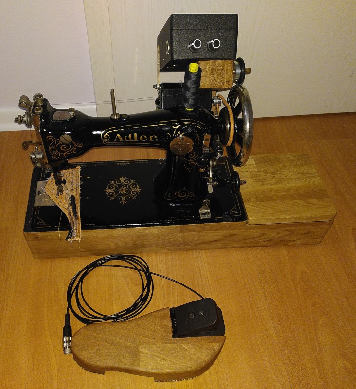
Bigfoot consists of a pedal with a Hall effect sensor, an infrared photointerrupter to detect the motor speed, and a control board with an Arduino and a 300VDC PWM driver to feed power to a standard sewing machine universal motor. That's "universal motor" as in "accepts AC and DC."

My Bigfoot runs on 230VAC, but all of the components were chosen such that it will run on 120VAC just as easily. All it takes is a different power cord and a 120 VAC motor in place of the 230VAC motor I used.

I use an Adler class 8 sewing machine to sew projects out of leather and Naugahyde.

The Adler was not made for that kind of thing - it was built for speed.  Punching through a few layers of leather doesn't bother it - I can sew leather with it with nothing more than one finger turning the balance wheel.

There was never a hand crank for the Adler as there was for many vintage sewing machines of the same age.  The Adler was made for professional use.  It had a treadle table.

My Adler has to get by with an aftermarket sewing machine motor.  Its table is long gone. Folks in Germany like to "upcyle" sewing machine tables as decoration.  The machines are then usually disposed of as junk - my Adler was a victim of someone else's "upcycling" project.

Leather is normally sewn with rather long stitches,  The combination of a fast sewing machine and long stitches means that the article you are sewing runs through the Adler very fast - too fast for me,  to be honest.

To make my Adler easier to use, I came up with the Bigfoot controller.

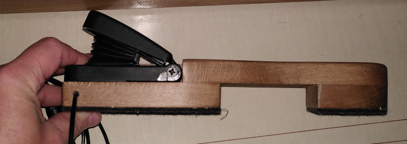
Bigfoot has a Hall effect go-kart pedal mounted on a custom floor pedal.  I find the commercial controllers uncomfortable - I have to bend my foot too far up to use them.  The Bigfoot pedal is made to be comfortable - most of the motion range is below flat footed.

The controller has a photointerrupter with a slotted wheel and a friction drive to pickup the sewing machine speed.  It is mounted on the motor such that the pickup rolls on the handwheel.

Inside the controller is an Arduino to read the motor speed and the foot pedal and to generate a PWM signal to drive the motor.

There's an isolated MOSFET driver to allow the Arduino to drive a MOSFET controlling 300VDC.  Typical sewing machine motors are universal motors designed to be driven on line voltage.  Full wave rectified 230VAC gives you 300VDC - and the universal motor is just as happy with that as it would be with AC.

The Arduino runs a PID controller to maintain the set motor speed.

Since I find manually tuning PID controllers to be really difficult, there's a pushbutton "tune PID" function built in.  Raise the presser foot, unthread the machine, press the button, wait while the machine runs the speed up and down for a few seconds, all done.   The PID coefficients are automatically stored in the Arduino EEPROM.

  • What do you do with a leather eating monster?

    Joseph Eoff11/19/2023 at 20:14 0 comments

    What do you do once you've converted your vintage sewing machine into a leather eating monster using the Bigfoot sewing machine motor control?

    You feed it leather, of course.

    The first test of the Bigfoot control was this leather and nylon carrying case that I made for my wife:

    Carrying case 2

    She sings in a choir and takes her Koenig and Meyer 100/1 music stand with her to practice.

    I spent a quiet Sunday afternoon today while she was at choir practice making something for myself with the help of my Adler and Bigfoot.

    I am an American, but I've lived in Germany now for over thirty years.  Some twenty years ago, my parents came over and spent six months in a rented house in a close by village.  They were here to see our kids, of course, but also to travel around and see Europe.

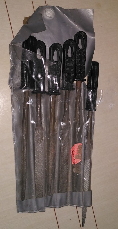
    While they were here, my Dad picked up a used child's bicycle for my daughter and stripped it down, fixed it up, and repainted it.  Somewhere in there, he had need of a set of small files - I'll be danged if I know what for.

    When they went home, he left that set of files here along with the electric lawn mower (and very long extension cable) he'd bought to take care of the yard in the rented house. 
    I still use the lawn mower and extension cable around my own house - and that set of files is still in my little workshop in the garage.

    When I went to use the files yesterday (to smooth the end of a screw I'd cut to mount a motor on a vintage Kayser vibrating shuttle sewing machine that I'm working on,) I noticed that the package the files were in was in pretty bad shape.

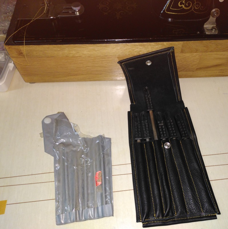
    I rooted around a bit, and found a couple of scraps of black leather that seemed big enough, and decided I'd make a new case to keep my Dad's files together.

    It's not like the files themselves are special - he bought them marked down from the "cheap stuff" bin in the local hardware store.  I could easily buy a new set, and in better quality.  He gave them to me, though, so I'd prefer to hang on to them.  Besides, they still work just fine so it'd be stupid to throw them away just to replace them with new ones in a better case.

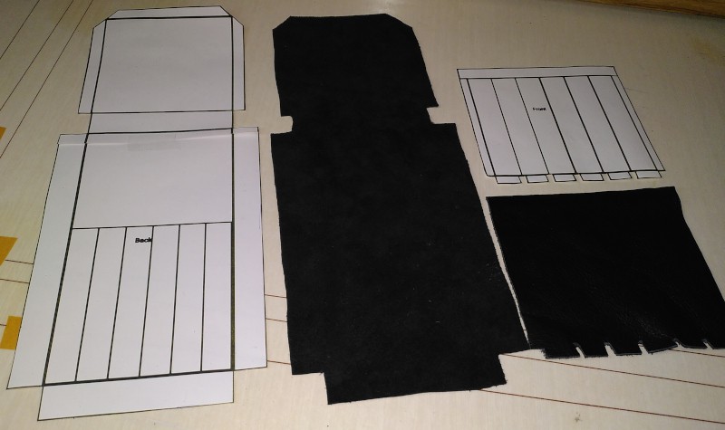
    I made some measurements, then sketched out a couple of patterns in Inkscape.

    Making the patterns and cutting the leather took longer than sewing the pouch together did.

    As I've mentioned, I'm not really all that good at this kind of stuff.  I like making things, but I need more practice in doing it.

    Still, scraggly and messed up as it is, the new pouch is better than the torn up and falling apart original pouch.

    The individual tool pouches aren't evenly spaced, the folded over edges of the cover flap aren't even, and the folded over bottom edge went crooked.

    If you want to get better, you've got to practice.  As long as the results are usable, even practice pieces are a win.  This one's a win.


    I hang on to a lot of stuff for such sentimental reasons. 

    My Dad gave me the Telequipment D43 oscilloscope I use for electronics, and for which I wrote the D43 oscilloscope camera software. I could buy a new scope - ones with features far in advance from the D43 are available for only a few hundred Euros.  I'd rather use my old analog buddy that reminds me of my Dad.

    I've repaired both the lawn mower and the extension cord I mentioned above at least one time each.  I've fixed them and kept them, and think of my Dad when I use them.

    My adult children got together and bought the vintage Adler class 8 sewing machine that I use.  If all I wanted were a full on leather sewing machine, I'd just go shell out a couple of hundred Euros for a used patcher and be done with it.  My kids gave me the Adler, though, and I find it to be one of the most beautiful machines I've ever seen - despite its age and wear.  I've learned more about sewing and sewing machines in getting my Adler to run than I'd have ever learned otherwise - including all the stuff that went into building the Bigfoot controller....

    Read more »

  • Bigfoot's big foot

    Joseph Eoff11/18/2023 at 21:29 0 comments

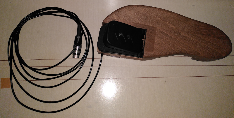
    I named the project Bigfoot because the foot pedal itself is modeled on my own oversized right foot.

    The pedal is made to be comfortable.  The usual pedals are too high and require me to either bend my foot upwards, or else hold my foot and leg in a sort of hover above the pedal.

    The Bigfoot pedal is made to support my foot so that I can work the pedal with just the ball of my foot.

    Let's take a look at Bigfoot's big foot:

    That's a beech wood foot with a "heel" and a "sole" to support it.  There's a layer of thick felt underneath it all to keep it from scratching the floor.
    The cable has three conductors for the signals and a steel cable to keep it from breaking if you pull on it hard - the steel cable is anchored in the connector and in the pedal. The connector is an Amphenol 3-pin screw in model.  It is really overkill and cost way more  than is reasonable for a personal project.

    The actual working part of Bigfoot's big foot is that black pedal.  It is a Hall effect accelerator pedal like this one on Amazon.  It has three connections: +5V, ground, signal.  The signal output is a voltage between about 0.2 and 4.8V that is linearly proportional to how far you have pressed it.  0.2V = all the way up, 4.8V all the way down.  It is as easy to read with the Arduino as a potentiometer would be, but it won't wear out the way a potentiometer would.  The hinges or the spring might give out, but I'm pretty sure the sensor won't.

    The pedal appearance doesn't quite match that of the sewing machine I use it with.  My Adler 8 sits on a shellacked box made of oak.  Bigfoot's foot is made of beech wood stained walnut with a coat of hardwood floor sealant instead of shellac.  I'd have made it of oak, but I didn't have any oak scraps left - I'd have had to buy about 30 Euros worth of wood for just that little piece.  I used hardwood floor sealant on it because I expect it will be kicked around quite a bit - shellac looks good but it isn't tough enough.

    The "design" is literally just  a tracing of my foot that I scanned into the computer.  I drew cutouts and mounting holes for the pedal using Inkscape then used the printed template to do the woodworking.

  • Bigfoot against a standard foot pedal - what's the big deal?

    Joseph Eoff11/15/2023 at 19:47 0 comments

    I've spent a lot of words trying to explain the difference between Bigfoot and other controllers, but I'm not really sure I've managed make the difference understandable to someone who hasn't tried to sew leather with a normal sewing machine.

    Typical foot pedals (and typical feet) lack the finesse needed to maintain a steady sewing speed while sewing leather.

    Bigfoot takes care of the finesse so that I can concentrate on the sewing.

    Here's my Adler class 8 trying to sew three layers of the kind of leather I normally use in my projects.  I've programmed the Bigfoot controller to work like a normal footpedal - push harder = more power.  If you hold your foot still, the power stays the same.  When the load changes (thicker or thinner spot in the seam,) the speed changes as well.  Since low speed means low power, it has a hard time punching through leather at a speed low enough for me to keep the seams straight.

    It has trouble getting started - as soon as the needle touches the leather, the motor stalls out and the needle gets stuck.  I have to reach over and turn the handwheel to get it moving again.

    Once it is moving, I have to maintain a steady (fairly high) speed to keep it from getting stuck again. Of course, I'm not that good at it, so the needle gets stuck again.  I have to break my concentration and reach over and crank the handwheel to get it moving again.

    On towards the end, it goes from three layers down to two, and the motor speeds up.  The faster it goes, the harder it is for me to keep the seam straight.

    For comparison, here's Bigfoot with its normal software.  It monitors the speed with the tachometer and the PID control maintains the speed I've set on the foot pedal.  I push the foot pedal, and Bigfoot makes the machine go - no matter the load.

    Bigfoot (with its tachometer and PID controller) has no trouble at all piercing the leather at low speed.  It maintains its speed even when transitioning from the thick, three layer part to the thinner two layer part.  The thumping on the first few stitches occur because the needle got stuck in the leather - Bigfoot merely applies power to maintain the speed and scrape the leather off the needle. 

    That difference in control allows me to concentrate on making straight seams.  I don't have to worry about it going too fast or getting stuck.  Just chug along, doing my thing.

    That second video is what has driven me these last few months.  I knew that typical sewing machine motors could sew leather but that the typical power regulating foot pedals were holding them back.

    --------

    Do you know how I knew that the motor could handle it?  It's because I can stick one finger through the spokes in the handwheel of the sewing machine and sew things without getting stuck.  There's no way I could exert 100watts (the rated power of the sewing machine motor) with one finger - or even 50watts if you assume the motor is only 50% efficient in converting electrical power to mechanical power.

    It doesn't take massive amounts of power.  It just takes applying it correctly.

    The Bigfoot controller applies the available power appropriately, and makes my sewing tasks much easier.

  • A tachometer for Bigfoot

    Joseph Eoff11/12/2023 at 15:46 0 comments

    Bigfoot needs to know how fast the sewing machine is really running in order to do its job.  For that, it monitors the rotation speed of the sewing machine balance wheel (also called the handwheel.)  

    Bigfoot uses a simple photointerrupter and a slotted disc to monitor the turning speed of the handwheel.

    I bought some photointerrupters from Amazon that included the slotted discs.

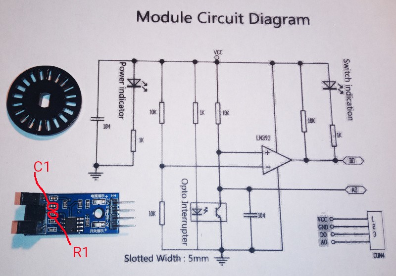
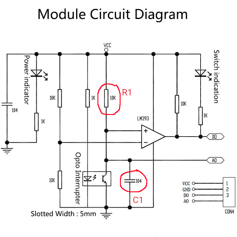
    There were some initial difficulties in using the modules.  It turned out that I needed to modify the circuit feeding the comparator on the modules to get a square wave signal from the tachometer.

    As delivered, the modules produce an asymmetric  signal at low speed, and no signal at high speed.

    Low speed:

    If you purchase similar modules, you need to modify them as follows:

    Remove C1 entirely and replace R1 with a 750 ohm part to get this much improved output:


    On typical sewing machines, one turn of the wheel is one stitch.  The slotted disc has 20 slots, so there are 20 pulses per turn of the disc's shaft.

    The handwheel is larger than the pickup wheel on the tachometer, so there are far more than 20 pulses per stitch.  Bigfoot has parameters you set before compiling so that it can calculate the correct number of stitches per minute from the length of the pulses.

    Bigfoot works internally with stitches per minute.  It figures RPMs for the pickup wheel, then converts that to stitches per minute to compare with a setting calculated from the foot pedal - also in stitches per minute.

    The tachometer is inside the little wooden box that rides the handwheel:

    The insides of the tachometer look like this:

    There's a bearing to the right there so that the axle runs smoothly.  The axle itself is a length of 8mm brass rod. The tachometer module is screwed to the bottom so that the slotted disc passes through the photointerrupter.  The wheel is an aluminum pulley with a rubber O-ring for traction.

    The box is made out of three pieces of 19mm oak board.  I cut them on a bandsaw, then used a wood chisel to make the pocket for the bearing.

    I've added some notes on the tachometer to the Bigfoot repository.

  • Safety first

    Joseph Eoff11/12/2023 at 14:57 0 comments

    When I put this project up, I specifically asked that anyone interested in it should ask for missing details.

    It took less than a couple of hours for [paulvdh] to ask some questions.  I'll deal with the most pressing question first:

    Yes, Bigfoot has a fuse.  I am well enough aware of my limitations as a hobbyist.  I know  that Bigfoot could at any time fail catastrophically, either due to a design error  (mine) or a construction error (again mine) or just because components do fail when you least expect it.

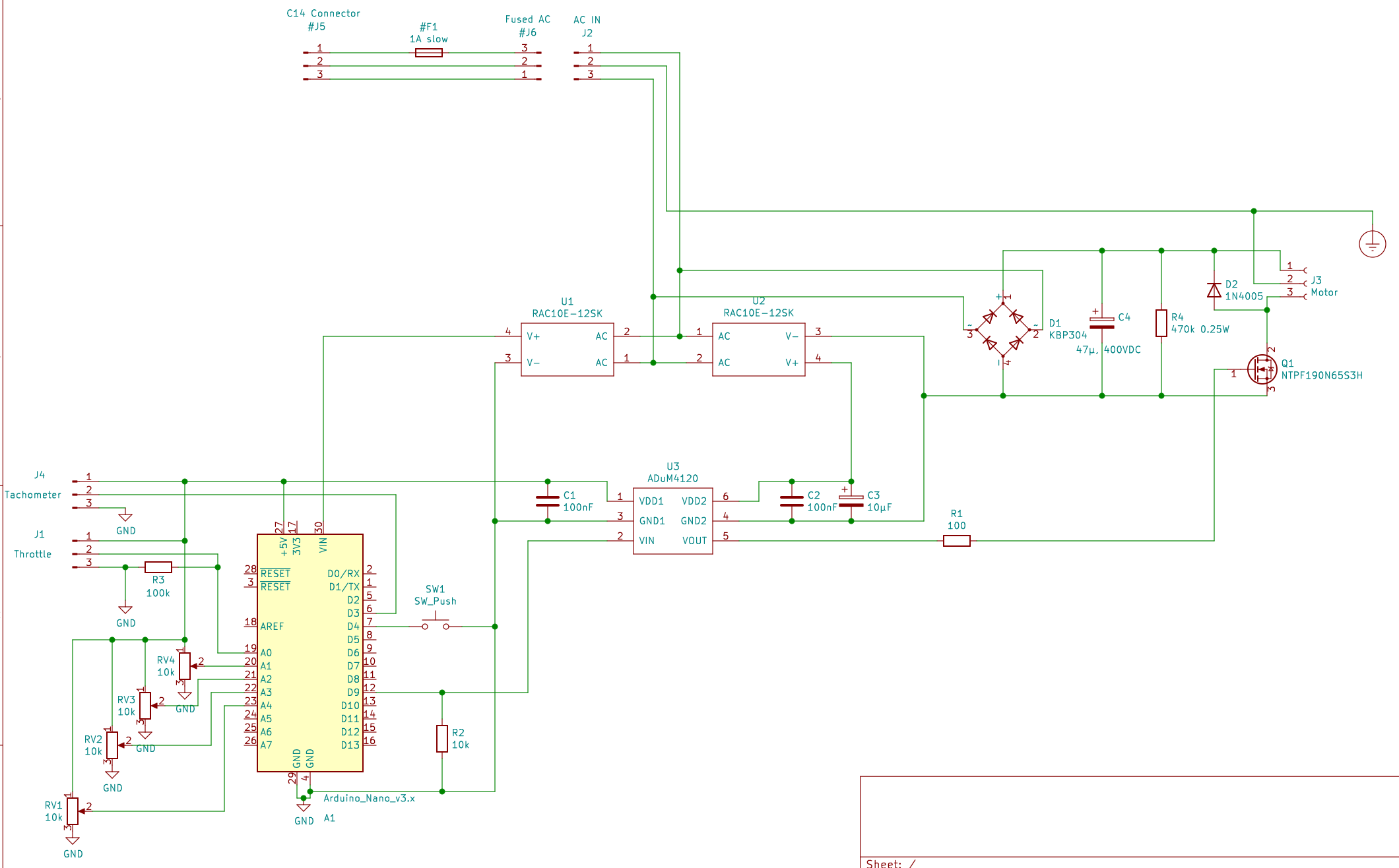
    I've updated the schematic with the missing pull down resistors and the bleeder for the 300VDC supply.  I also added the C14 socket and fuse to make it clear that they are required.

    The PCB is laid out to the best of my ability to separate high voltage from low voltage.

    Bigfoot has two 12V power supplies.  One powers the Arduino, the tachometer, and the low voltage side of the isolated MOSFET driver.  The other 12V power supply powers the high voltage side of the isolated MOSFET driver.

    Keeping things isolated like that means that I don't have to take any special care with the controls - they are all at low voltage and isolated from the mains voltage.

    The housing is made of aluminum.  Since there's AC line voltage and 300VDC loose in there, I have the housing connected to the safety ground - the power cord is a three wire cord with a safety ground.

    Typical sewing machine motors don't have a safety ground - that has always made me very nervous since the things have a metal housing connected to the metal housing of the sewing machine - and they run on line voltage.

    I ran an extra ground wire to the motor on mine along side the 300VDC power output.

    I've made Bigfoot as safe as I know how.

    If you want to duplicate Bigfoot, please be sure that you know how to work with mains voltages safely.  There are tutorials out there on the internet.  Find some, read them.  Be very careful with Bigfoot's internals - it can kill you if you mess up.

  • Share and share alike

    Joseph Eoff11/11/2023 at 22:05 0 comments

    I tend to post my project design files and code on GitHub.  I make use of open source software to get my projects done, so I figure it is only fair to make my stuff open source as well.  That is, I use all kinds of free and open source programs to do the design and programming, so I make my finished stuff open source as well.  I also do my best to follow the licensing requirements of the libraries I use.

    Bigfoot is no exception.

    I posted all the stuff I designed and all the information I gathered into the Bigfoot repository.

    It's all there, though it is at the moment a bit of a mess.  Schematic, PCB design, mechanical drawings for the hardware I built, datasheets for all the components I used, etc.

    There are two versions of the Arduino software.  There's  the version I am currently using, which includes a PID controller and a PID autotuner, then there's a simple version that simply regulates power - it doesn't try to maintain the speed, it works like a standard sewing machine pedal.

    The PCB design needs to be updated - I made a couple of small mistakes that I corrected when I assembled it, but I haven't gone back and corrected the KiCad files.  There's a couple of pull down resistors missing, and there's a bleeder resistor missing on the 300VDC power supply.  They are tacked on my PCB, but they aren't in the KiCad files.

    Take a look.  Leave a comment here or open an issue on the repository if there's something you need to know but can't find.

  • A beginning and an end - and more to come

    Joseph Eoff11/11/2023 at 20:59 0 comments

    Bigfoot has been a long time getting here.  I started developing Bigfoot nearly two years ago.  I initially wanted to make it work without a separate tachometer, but experiments showed that controlling a universal motor at low speed using the back EMF method would be rather chancy.

    I suppose I could have gotten done faster, but I backed up and wrote blog posts explaining just why the common sewing machine foot pedals weren't adequate for what I want to do.  I backed that up with some demonstrations, then went on to do some experiments in detecting motor speed with back EMF and PID controllers.  It has been something of a learning experience for me. In the end, I went with a photointerrupter tachometer, and worked out how to attach the controller and the tachometer to the sewing machine all in one piece.

    The final product is larger than I originally intended, but it is at least self contained.  It should be possible to make it smaller.  A large as it is, it can still be readily retrofitted to many vintage sewing machines - any machine with an external motor or a boss for a hand crank can use a modern aftermarket sewing machine motor with Bigfoot to control it.

    Here's Bigfoot helping my Adler class 8 sewing machine stitch its way through varying thicknesses of Naugahyde (PVC fake leather.)

    Where it starts, there's eight layers of fake leather.  It drops down to two layers, then goes back up to four layers.  The speed remains constant through all sections.

    The constant speed is needed because if the machine drops below a certain speed, the needle will get stuck in the material.  It isn't as critical with Naugahyde, but in real leather the needle can stick badly enough that it can be difficult to get it moving again even by hand.

    The slow speed is needed because I'm not all that good with a sewing machine - I need time to keep things lined up so that the seams are straight and run where they belong.

    That's the beginning and the end of the Bigfoot story.  I'll add some logs later to explain what went into getting Bigfoot to do what it does - and just exactly what it is that makes Bigfoot different.

View all 7 project logs

Enjoy this project?

Share

Discussions

Joseph Eoff wrote 11/18/2023 at 07:48 point

Hello, Paul.

I am indeed using the "gotPulse" to guard against reading from the "pulseTime" array while the ISR might be writing to it. 

"SlapMotor" has two use cases:

1. When starting from a dead stop, "SlapMotor" gets things rolling.  Sometimes the motor stops on the edge of a slot.  Without that blind slap, the first pulse either comes too soon (impossibly short pulse time) or not at all (the first PID output isn't enough to get it rolling.)

2. At low speed, there may be a "wobble" at the edge of a slot.  This also results in an impossibly short pulse time.  The slap forces the motor past the wobble.

A fancier encoder isn't needed.  There's a lower limit imposed by the material being sewn.  If the needle moves too slowly, the leather will "grab" it and not let go.  The setup I have now will get me below that limit.  For thicker stuff, you must move just a bit faster.  I can cover that with the low speed adjustment knob.

  Are you sure? yes | no

Dan Maloney wrote 11/18/2023 at 04:01 point

Great hack, thanks for sharing. I wrote this up for the blog, should publish soon. Thanks!

  Are you sure? yes | no

Joseph Eoff wrote 11/18/2023 at 07:50 point

Hello Dan.

Thanks for the heads up.  I'll keep an eye out for it.

  Are you sure? yes | no

paulvdh wrote 11/11/2023 at 23:50 point

This looks like quite a nice project.

I also like the simplicity of running an universal motor from rectified mains. My own interest is into using other universal motors (from angle grinders, hand drills etc) for purposes they are not made for ;)

I wonder if you notice a difference when running the motor on 310Vdc instead of 230Vac. DC instead of AC lowers the motors impedance, and the higher voltage may lead to overheating problems when run at full power (which is probably never done with proper PID, but it might be a good thing to limit the duty cycle to compensate.

I am missing a fuse though. Motor controllers like this should have a fuse to prevent fires from failing electronics. Especially with home brew experimental products like this.

I also noticed you added a lot of datasheets to your github repository. Nice, but I am missing any info about the tacho. Can you add some info about that? Even if it's just a repurposed brushed toy motor it's good to know. Maybe add a picture of the mechanical setup?

  Are you sure? yes | no

Joseph Eoff wrote 11/12/2023 at 00:12 point

Hi, Paul.

There actually is a fuse.  It is in the power cord socket.  I need to redraw the schematic to show it.  It needs to be in the schematic so that folks know it is there, but it also needs to be flagged in some way so that KiCad doesn't expect it to be placed on the PCB

The tacho is a slotted disc and a photointerrupter.  If you follow the links to my blog post series, you'll find more details about it. I bought the photointerrupter and disk from Amazon.  The photointerrupter circuit has to be modified slightly to work properly.

I'm going to add project log entries here, but I haven't gotten around to it yet.

The only noticeable difference between running on AC or running on DC is that the motor doesn't hum on DC.  Other than that, I couldn't tell you if it has more (or less) power.

The thing that matters here is that the power is regulated.  The motor gets what it needs for the load and the desired speed.

The PWM drive makes a difference in so far as even at low speed the motor is getting the full 300VDC. The torque should be better at low speed because of that.  It is hard to tell, though, since the PID control pretty much gives you all the torque the motor is capable of any time it is needed.

  Are you sure? yes | no

paulvdh wrote 11/18/2023 at 02:25 point

For the fuse, with newer versions of KiCad, you can simply edit the properties of a symbol and set the "Exclude from board" attribute.

I can confirm (at least for a brushed DC motor) that you can get a bit lower RPM with PWM compared with a steady DC voltage. Using a low PWM frequency also helps here. Especially when the PWM frequency is lower then the motor inductive time constant, the motor gets Torque pulses" which then get integrated by the motor inertia. But it is a bit finicky, and also has disadvantages, gears may start rattling or other extra wear, and the effect is limited anyway.

With PID you can get much lower RPM then without feedback, but the encoder you use (thanks for the extra picture) is lacking resolution to get to really low RPM's. I can recommend the Omron E6B2 (clones?) as encoder. They are full quadrature so you can also derive direction and position, but more importantly, it's everything (axle, bearings, encoder disk, electronics) in a neat package, and you can get them with varying resolution (up to 2048 pulses per revolution). Also, just using a smaller rubber wheel increases the encoder RPM and thus resolution of the feedback.

I see that you calculate the speed from the pulseTime[] array, and that is a good way to calculate the speed, because you get a speed value from each encoder slot. A limitation with DIY encoders is that variations of width in the encoder slots will cause jitter on the calculated speed. You are also updating this from an ISR, and then using it in your normal program, and that will not work reliably. Every now and then the ISR will trigger while the main program is reading that variable, and the main program will read a long that is made up out of the result of two different measurements. It is quite possible this is the reason you needed SlapMotor(), because the light bridges usually have a built in hysteresis. But it is also better to use the raw time differences for such things. If the time difference is off, then the input is unusable, and there is no use of going though the float calculations. It looks like you are using the gotPulse variable as a semaphore to guard for this error, but I have not analyzed the code fully.

  Are you sure? yes | no

Similar Projects

Does this project spark your interest?

Become a member to follow this project and never miss any updates