-
Web-Based UI for MetaShunt V2
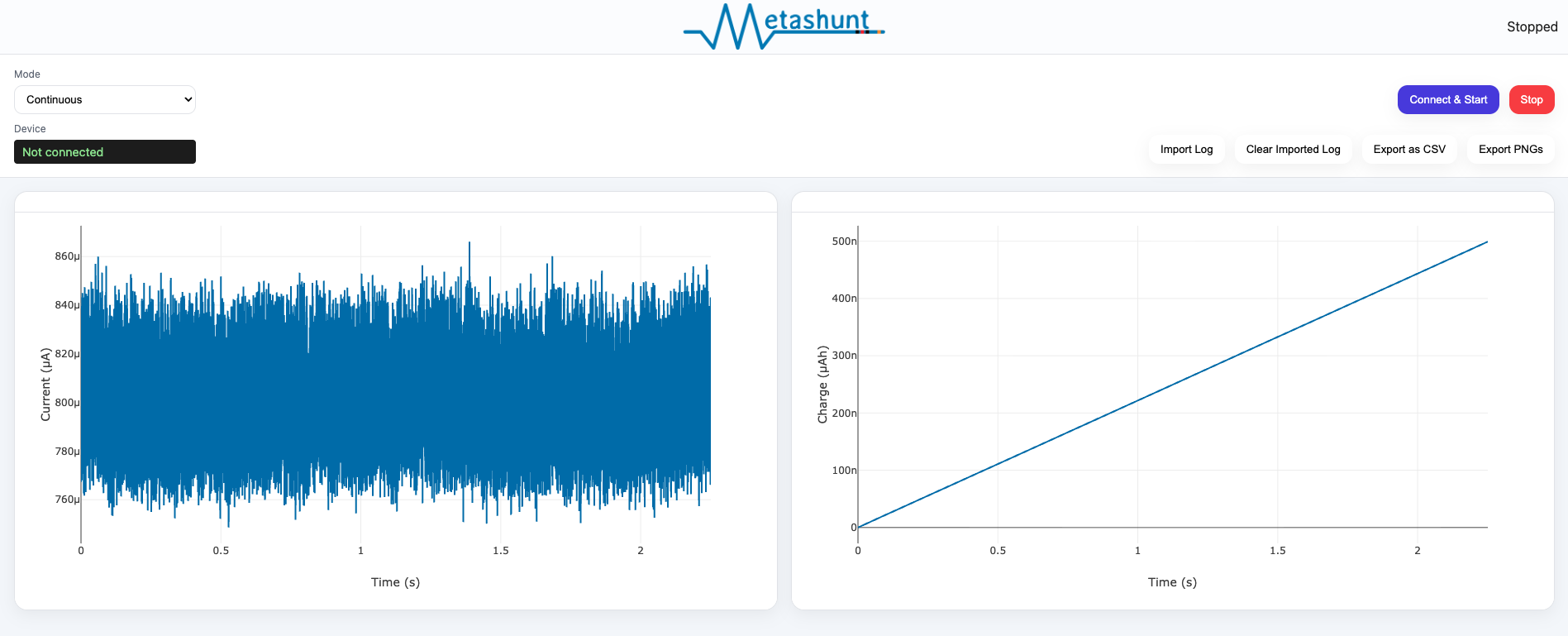
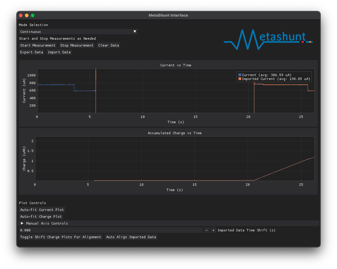
01/31/2026 at 17:04 • 0 commentsAlthough the current Python UI is sufficient for using MetaShunt V2, it isn't the most user-friendly. Those who know Python and/or are developers may find it easy enough to set up, and may prefer the ability to script the interface, but I wanted to make a simpler option. Therefore, I built a new, modern GUI for MetaShunt V2 which is hosted on Github Pages and provides a web-based interface using webserial. It is cross platform, works on Chrome and Edge, and requires no installation! Check it out at https://jwachlin.github.io/metashunt-web-ui/ or check out the source at https://github.com/jwachlin/metashunt-web-ui.
Using this GUI, you can make measurements, zoom in and out on charts, export data as a CSV file, export plots, and import past measurements for side-by-side comparisons. It supports continuous measurement as well as burst-mode measurements. Try it out and let me know what you think!
![]()
-
Power Profiler Kit II (PPK2) vs MetaShunt - Accuracy Implications for Ultra Low Power and IoT
12/23/2025 at 18:45 • 2 commentsAfter confirming the better than 1% calibrated accuracy of MetaShunt V2 in the previous logs, I wanted to go back to compare results against the Power Profiler Kit II (PPK2) from Nordic Semi. The PPK2 is the go-to power profiling tool for most hobbyists, but the +/- 10% accuracy of the PPK2 can lead to issues in power profiling. With that level of uncertainty, it can be difficult to discern issues with firmware. Is that subsystem of your project actually off? If it takes 10% of expected current, how do you know?
This blog post will cover three topics. First, a very low power example with the Nanosleeper development board, looking at current measurements and what that implies for battery life estimates. Second, focusing in on the implications of accumulated charge measurement, and how MetaShunt V2 LT separates the measurements from being tied to a computer for long-term measurements. Third, a higher power ESP32 example, comparing the results between the PPK2 and MetaShunt V2 for IoT applications. Let's take a look!
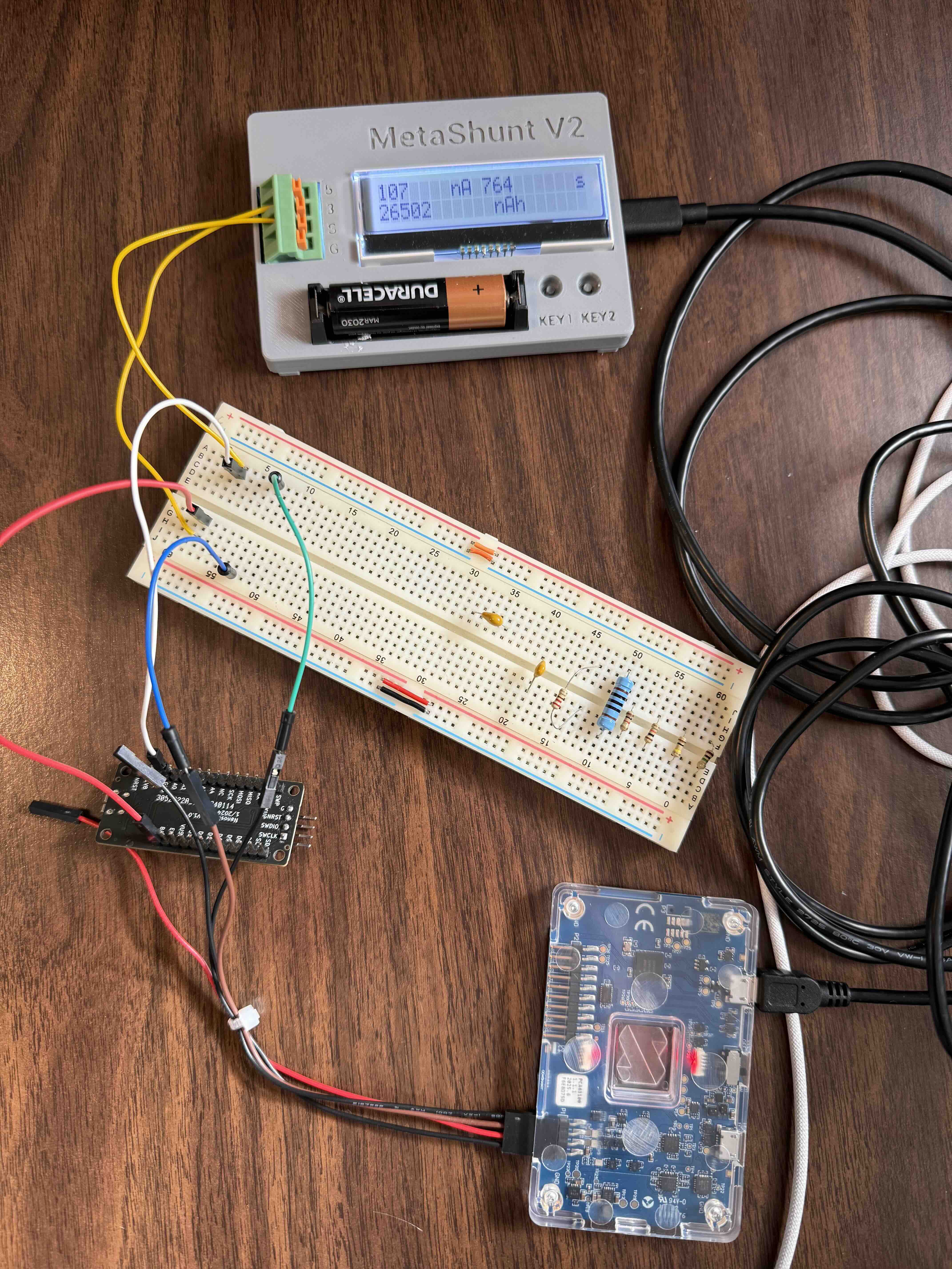
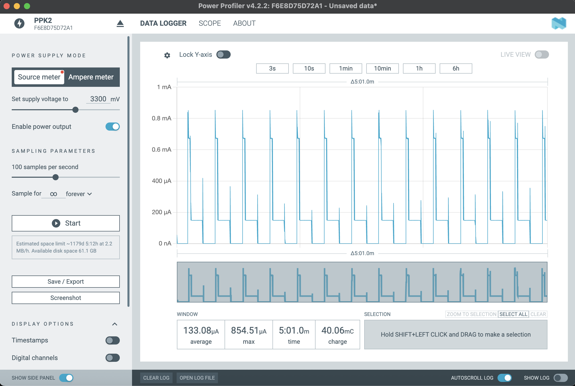
Nanosleeper Current MonitoringNanosleeper was set up to periodically wake up, flash LEDs, busy wait, enter low power mode, then enter deep sleep. The pictures below show the physical setup, and screenshots from the PPK2 GUI and the MetaShunt V2 GUI.
![]()
![]()
![]()
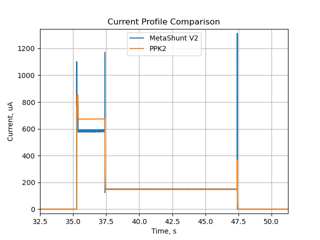
From these views, it is hard to tell what's going on. If you didn't know better, you might believe that the PPK2 results are reliable, since the profile matches what is expected. However, when we plot the data on top of each other and zoom into a single wakeup cycle, we can see the significant differences in results. The current is especially different in the busy wait section, where PPK2 indicates the current is about 673uA, while MetaShunt V2 measures current at 584uA. This difference of 89uA is 15% larger than the MetaShunt's measurement! Note that the apparently higher noise of MetaShunt V2 is because in this test the PPK2 data was averaged out to 100 S/S, while the MetaShunt data is about 6,000 S/S.
![]()
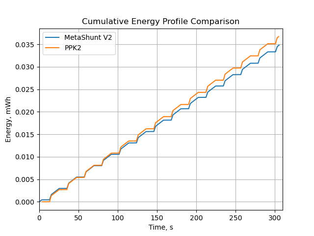
Nanosleeper Charge AccumulationOne key feature of MetaShunt V2 LT is the ability to, without a computer externally recording and accumulating data, monitor accumulated charge. The PPK2 GUI can do this, but requires logging of data, which adds up quickly and is logistically difficult over days-long or months-long tests. For this example, we also compare the energy over time (assuming 3.3V) for both MetaShunt V2 and PPK2. This is shown in the plot below. Note it diverges over time.
![]()
From the PPK2 GUI, we see a charge accumulation of 40.06mC over 301s. I took a picture of MetaShunt V2's display at 300s, which indicated 10,335 nAh. If we scale the PPK2 data back to 300s, it is 39.93mC, or 11,092 nAh. This is a difference of 7.3%, which can be quite significant! As we saw in the previous section as well, the biggest inaccuracy was during busy wait mode, and if Nanosleeper was in busy wait mode for a larger portion of time, this charge accumulation difference would be larger. Remember also, if this test were longer than 5 minutes (days-long or months-long), the PPK2 would need to be actively logging to a computer with GUI up and computer not going to sleep, while MetaShunt V2 can simply be connected to any USB power supply.
ESP32 ComparisonTo compare a higher-power, IoT focused example, I powered an ESP32 development board with the PPK2, while using the MetaShunt V2 LT as a low-side, long-term charge accumulation measurement tool. Due to isolation issues, it wasn't possible to have both log simultaneously, but we can compare the total charge accumulation after 5 minutes. The pictures below shows the connection and the results from the PPK2. Note that the current is significantly higher than the Nanosleeper tests.
![]()
The screenshot and image below show the PPK2 results and results from the MetaShunt V2 LT after 5 minutes.
![]()
![]()
Over 302.6 seconds, the PPK2 measured 2.78C, which scaled to 300s is 2.76C. This is equivalent to 767uAh. MetaShunt V2 LT measured 780 uAh over the same 300s, about 1.6% more. In this higher current application, it appears that the PPK2 is measuring more accurately than it was for the low current of Nanosleeper, but nonetheless for long-term measurement MetaShunt V2 LT makes use so much easier than the PPK2.
-
Calibration Tool Completed and Accuracy Tested
12/21/2025 at 19:06 • 0 commentsI built the calibration tool mentioned and prototyped on the previous log, and it is open source and documented on another Hackaday project here. This calibration tool can provide a precision current supply to MetaShunt, which we can use for calibration and performance testing.
I recently analyzed the accuracy of the precision current supply here, and showed that the accuracy is quite good, typically better than +/-0.3%. A calibration script using a fixed reference device was developed and used on MetaShunt V2. This script is open source and listed here.
![]()
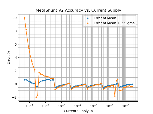
This calibration script was used on a MetaShunt V2, and then several days later a calibration test script was developed here, and tested with that MetaShunt and an adjustable reference voltage configured current supply. This was a physically different current supply. For this test, 75 different current commands were tested, from 50nA to 250mA, distributed linearly on a log scale. For each current command, I measure for 1 second and compute a mean and standard deviation of the roughly 6,000 measurements that are received back from MetaShunt V2. I then plotted the error of the mean measurement and a 2-Sigma error for each. The plot below shows the accuracy across the current supply scale. Across the entire scale, the MetaShunt V2 provides highly accurate mean measurements, within +/-0.6% of the commanded current. Combined with the +/-0.3% error of the current supply, this indicates better than +/-1% absolute accuracy for 1s mean measurements across 50nA to 250mA. At very low current, the standard deviation varies significantly, likely due to the high impedance of the measurements at this scale.
![]()
-
Calibration Tool for MetaShunt
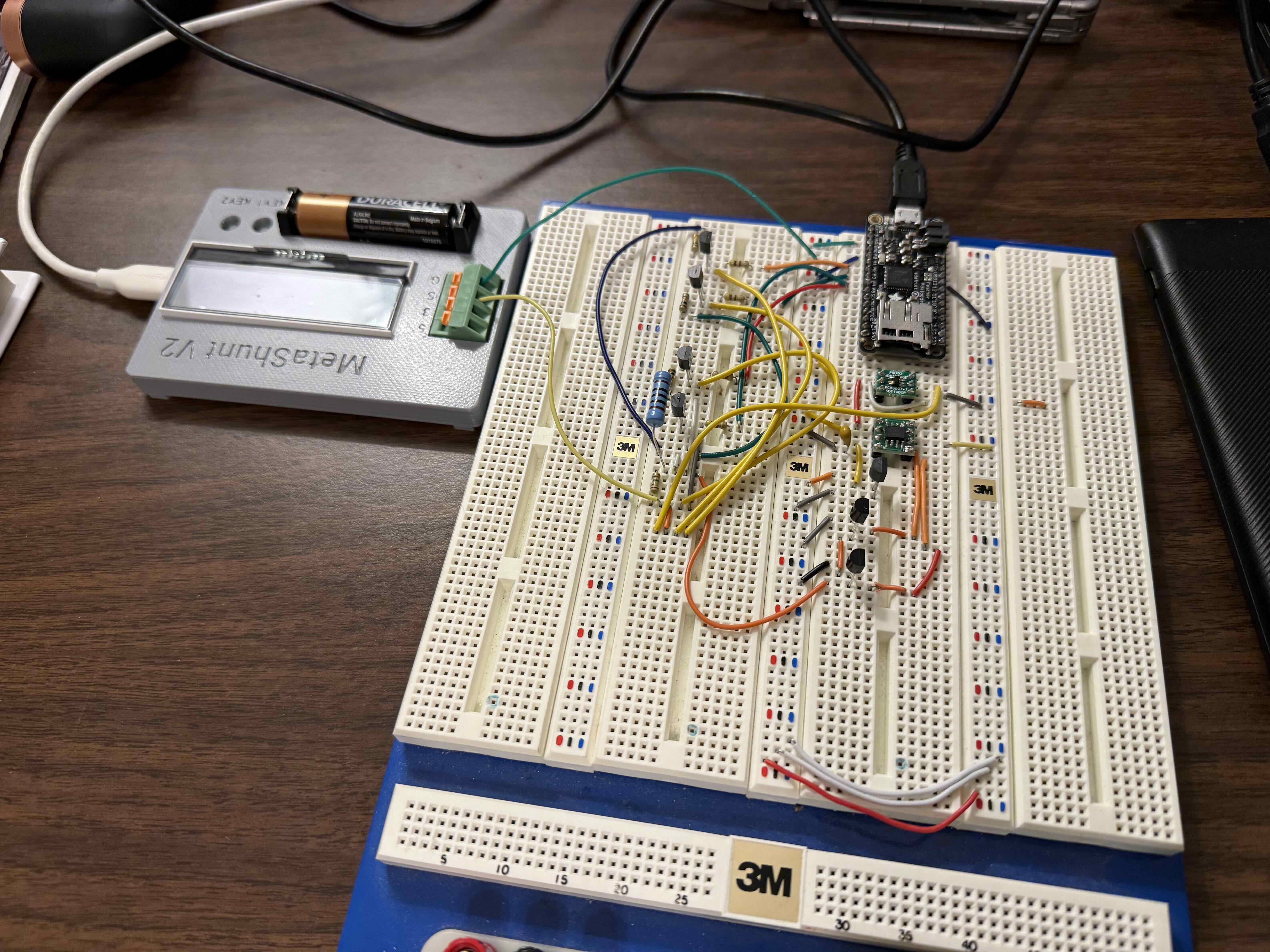
08/17/2025 at 02:35 • 0 commentsTo enable improved accuracy of MetaShunt V2, it would be nice to be able to calibrate at each of the 8 gain stages. With this in mind, I developed a high dynamic range current supply. To test the concept before ordering a custom PCB, I developed an equivalent breadboard version with the first 5 gain stages, seen below. The actual design has isolated power and isolated communications, so it can be connected to the same USB hub as MetaShunt without issue. This prototype however is not isolated, and so was powered by an external USB battery pack. An Adalogger M0 is used to control the gain stages, changing them every few seconds while I record the measured current on MetaShunt V2.
![]()
I measured all of the relevant resistors and voltage reference in this design, and calculated the sourced current. Then I measured the current with MetaShunt V2 and compared the difference. The real design will use highly accurate components (0.1% resistors, 0.2% voltage reference, etc.) but for this test I am just measuring the components with a multimeter (accuracy unknown).
Expected Current Measured Current Error 2.39uA 2.39uA 0.0% 27.2uA 27.35uA 0.55% 254.4uA 255.7uA 0.51% 279.2uA 280.2uA 0.36% 2.525mA 2.528mA 0.12% 2.801mA 2.801mA 0.0% 24.813mA 24.685mA -0.52% 27.615mA 27.415mA -0.7% So overall, fantastic accuracy across the board, and proved out the concept! Next step is to build the full system and build automatic calibration software for MetaShunt to improve it's accuracy even further. Nonetheless, even without calibration, MetaShunt is currently within 1% of the true current across 5 orders of magnitude in this testing!
-
MetaShunt V2 Case
08/16/2025 at 17:08 • 0 commentsMetaShunt V2 Now Has a Case!
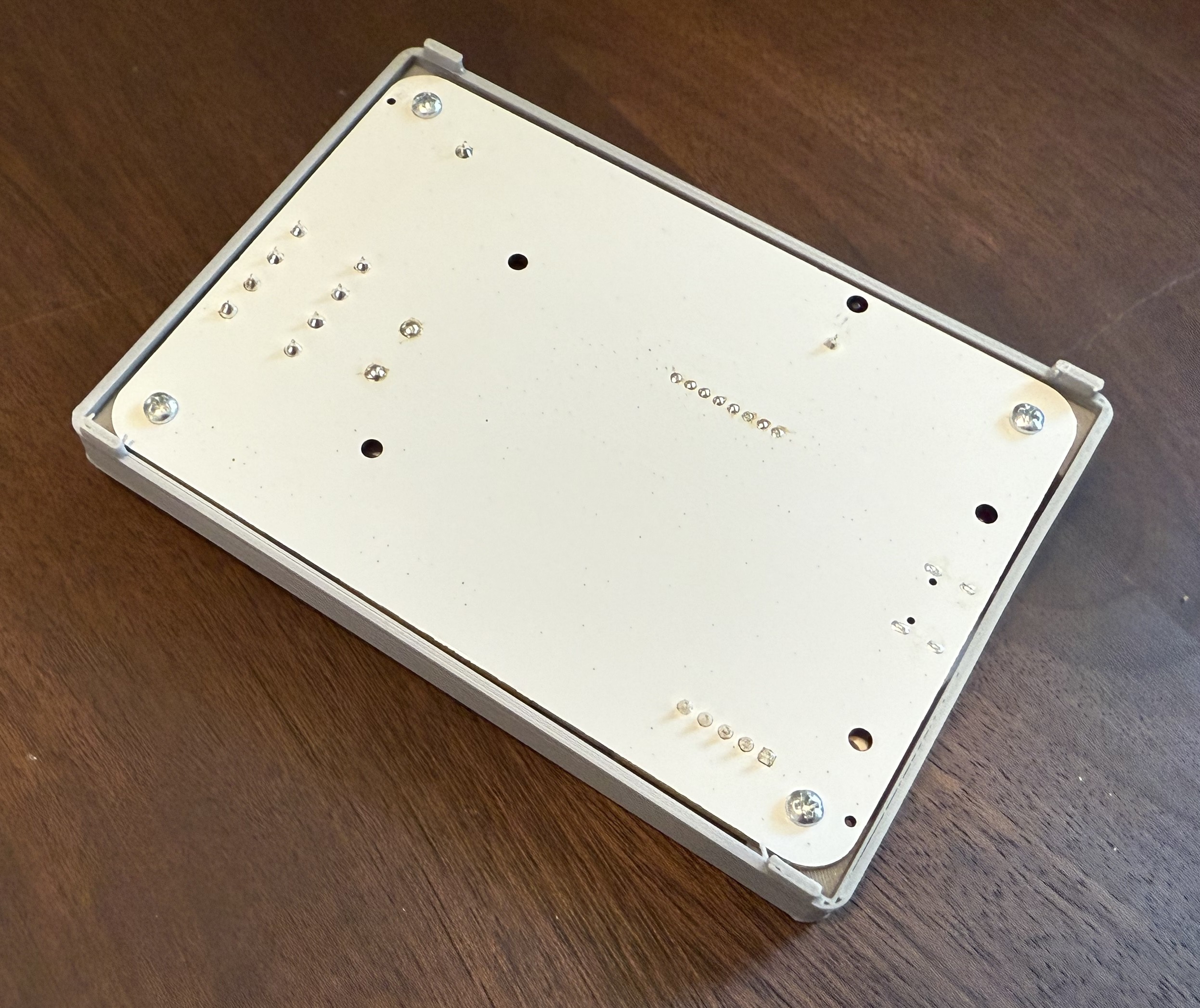
I recently designed a simple, 1-part 3D-printed case for MetaShunt V2. Versions are available for the LT and Base models on the main page. The designs are given as is, and can be modified with no restrictions. STLs and FreeCAD files are provided for both. For both versions, this screw from McMaster Carr is used to mount the PCB into the case. I recommend printing it with the text down on the build plate, no supports needed (worked well in PLA+ on my printer).
![]()
![]()
![]()
-
Nordic PPK-2 vs MetaShunt V2 vs Otii Arc Pro - Low Current Testing
06/30/2025 at 22:36 • 0 commentsI recently purchased a Nordic PPK-2 development kit in order to compare its performance with the MetaShunt V2 and the Otii Arc Pro. These three products compete but have very different price points, and each has its own unique feature set. The table below compares the three on high-level specs. All specs are accurate at the time of writing.
Product Price Performance Unique Features Nordic PPK-2 $89 Up to 100 ksps output, 200nA-1A range Highest continuous output data rate, digital input sampling, SMU capability MetaShunt V2 $199-$249 Up to 6 ksps output continuous, 127 ksps burst, 50nA-1.5A range Optional long-term computer-free coulomb counting, highest burst data rate Otii Arc Pro $949 Up to 4 ksps, "nA to 5A" range SMU capability, (paid) battery simulator, NIST traceable calibration
Test SetupThe device under test was my ultra-low power development board, the Nanosleeper. Firmware was set up on the Nanosleeper to busy wait with the two onboard LEDs on for 2s, then busy wait for 1.5s with the LEDs off, then enter the STOP0 sleep mode for 5s, then enter the shutdown sleep mode for 5s. This cycle then repeats. Data was captured using each of the Nordic PPK-2, MetaShunt V2, and Otii Arc Pro, respectively. The data was output to CSVs, and then compared using the log comparison tools on the MetaShunt interface repo. Prior to testing, MetaShunt V2 went through its normal production calibration process, which actually only calibrates the high current ranges, and therefore did not effect this test. The Otii Arc Pro calibration process using the Otii 3 software was performed. The PPK-2 was not calibrated, since I was not able to find anything online about it or any way in their software to calibrate it. For each test, 3.3V was provided into the BAT pin on the Nanosleeper.
ResultsThe plot below shows the measurements for the three tools on top of each other. Even in this zoomed out view, it can be seen that the Otii Arc and MetaShunt V2 agree closely at the higher currents. The plots at lower currents in the sleep modes appear to be on top of each other at this scale, so later plots will show the accuracy of those.
![]()
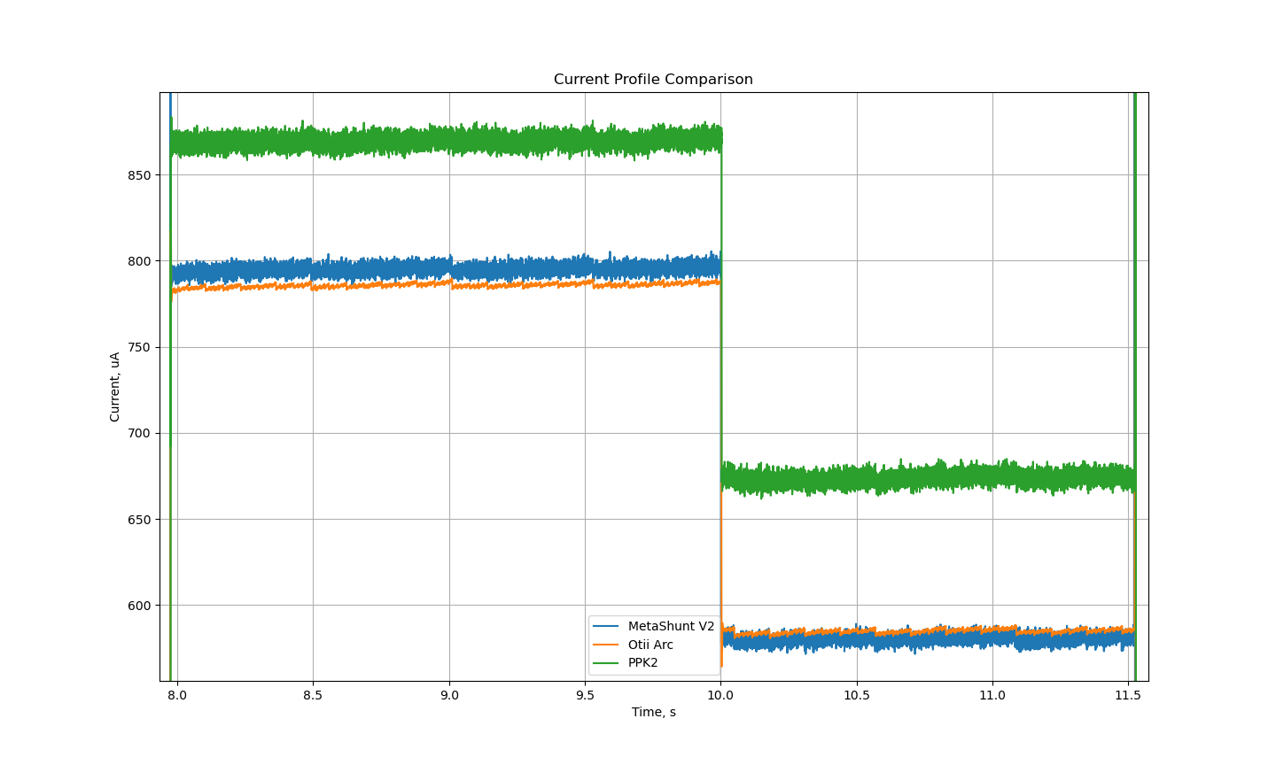
The plot below shows the measurements in the two higher power conditions. For reference, a cheap multimeter in ammeter mode measured the current as 787uA and 583uA, indicating that the Otii Arc and MetaShunt V2 measurements appear to be far more accurate than those from the PPK-2.
![]()
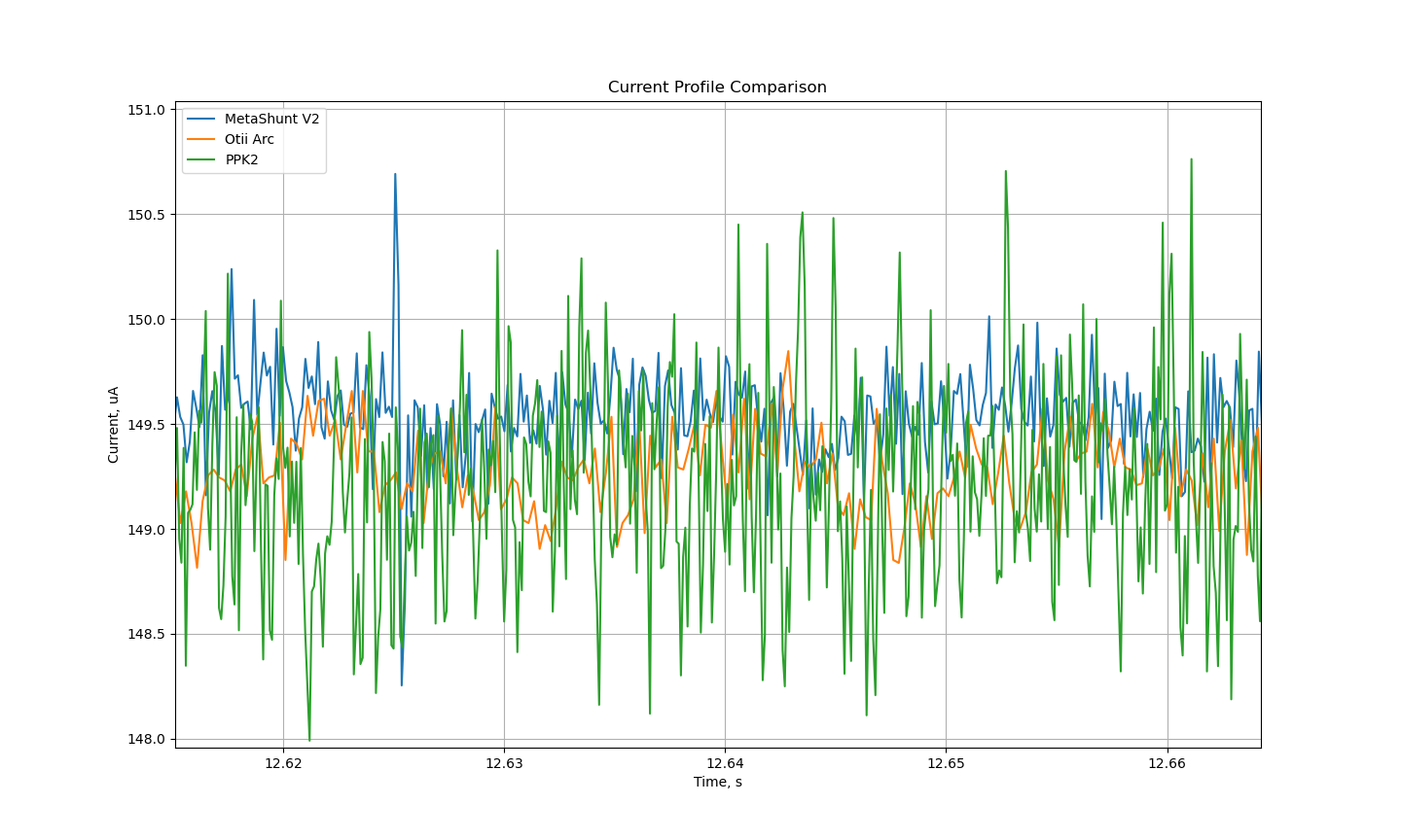
Interestingly, the current measured in the STOP0 sleep mode was very similar for all devices. The low-cost multimeter measured 146uA, for reference.
![]()
In the lowest power shutdown mode, I expect the current to be on average just below 100nA. This is below the spec of the PPK-2, but MetaShunt V2 and Otii Arc should be able to measure it. However, at this low current the noise level on the Otii Arc Pro nearly drowns out the signal.
![]()
The energy plot below shows the cumulative energy use over time. The Otii Arc and MetaShunt V2 lines track each other almost perfectly, while the PPK2 plot diverges fairly significantly. If using these tools to predict battery life, this would lead to significant uncertainty in expected lifespan of your device!
![]()
If we assume the NIST-traceable calibrated and ~5-10X more expensive Otii Arc Pro is the gold standard here, we see errors of the following:
On, LEDs On On, LEDs Off MetaShunt V2 Error +1.2% -0.8% Nordic PPK-2 Error +10.8% +15.5%
ConclusionThe Nordic PPK-2, MetaShunt V2, and Otii Arc Pro are all useful tools in low power and battery powered systems development and testing. They come in a range of price points from $89 to $949, and while they have a varied feature set, all three focus on a core capability of measuring current across a very high dynamic range. The MetaShunt V2 performed within about 1% of the accuracy of the Otii Arc Pro at about 1/5th the cost. The Nordic PPK-2 was the lowest cost tool of the three, but had poor accuracy (up to 15.5% measurement error) that would limit its usefulness in practice.
-
MetaShunt V2 GUI
05/03/2025 at 03:40 • 0 commentsToday I am proud to announce the launch of the first MetaShunt GUI, available now on the MetaShunt Interface Github repo!
![]()
![]()
Previously, the only interface to use MetaShunt V1 or V2 was a set of Python scripts which would allow for continuous (for a set amount of time) or burst measurements. At the end of the measurements, a set of plots would pop up. The user could alternatively tell the system to write the measurement data to a log instead of displaying it on a plot. A separate set of Python scripts enabled comparing two or more logs with each other, in order to analyze relative power consumption.
While functional, these were not user friendly. All that has now changed with this GUI!
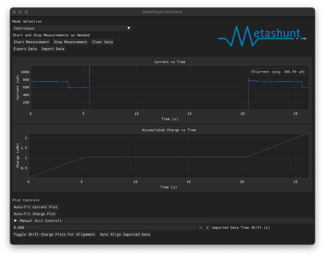
Users can now request continuous or burst measurements. While continuously recording, the plots auto-update, showing what is currently happening with the system. Burst measurements stop updating after the set of 37,500 datapoints in the burst have been received. Data can be exported and imported as desired, allowing measurements to be easily compared!
![]()
The imported data can then be shifted in time manually using the buttons near the bottom of the screen. Or, if the signal has recognizable features, the "Auto Align Imported Data" button can automatically align the data based on the current measurements. In addition, the charge over time plots can be aligned with the "Toggle Shift Charge Plots For Alignment" button. This button is key to compare wakeup events between firmware changes to compare energy savings easily.
![]()
Check it out for yourself now and please let me know if you run into bugs or have feature ideas! Happy hacking!
-
New MetaShunt Interface Feature - Comparison Tools
03/25/2025 at 13:00 • 0 commentsMetaShunt was designed for high dynamic range current measurement of embedded systems, particularly ultra-low power and IoT systems. These measurements help verify the functionality of a project or product. They tie in nicely with the power budgeting tools I've also developed, hosted on Hackaday.io here. However, I previously hadn't connected the two. This log demonstrates the new comparison tools I've added to the MetaShunt Interface Github repo, how they work, and provides some examples of their use.
First, lets look at the basic use of these tools - where they are located and what the interface looks like. The comparison tools are included in a folder on the MetaShunt interface. The key Python file to look for is metashunt_profile_processing.py. This can be used to set up the comparison plots between the outputs of MetaShunt V1, MetaShunt V2, Otii Arc, and my modeling tools. Each has its own enumeration to tell the parser what type of file it is, and the files can be temporally aligned manually, with no alignment, or by attempting cross-correlation (which may or may not work depending on what your signal looks like).
Next, let's look at an example. In this example, my Nanosleeper development board is operating between run mode, run mode with LEDs on, and deep sleep mode. The script to view this example is in the Examples/Nanosleeper folder for the Comparison Tools on the metashunt_interface repo. The code is very simple.
import sys

sys.path.append('../../')

import metashunt_profile_processing as mpp

if __name__ == "__main__":
    metashunt_profile_1 = mpp.PROFILE(filename="metashunt_v1_nanosleeper.csv", filetype=mpp.FILETYPE.METASHUNT_LOG,
                                      alignment_type=mpp.ALIGNMENTTYPE.TIMESHIFT, label="MetaShunt V1", t_shift=-6.1659)

    metashunt_profile_2 = mpp.PROFILE(filename="metashunt_v2_nanosleeper.csv", filetype=mpp.FILETYPE.METASHUNT_LOG,
                                      alignment_type=mpp.ALIGNMENTTYPE.TIMESHIFT, label="MetaShunt V2", t_shift=3.26803)

    arc_profile_1 = mpp.PROFILE(filename="otii_arc_nanosleeper.csv", filetype=mpp.FILETYPE.OTII_LOG,
                                      alignment_type=mpp.ALIGNMENTTYPE.TIMESHIFT, label="Otii Log", t_shift=0.0)
    model_profile_1 = mpp.PROFILE(filename="Nanosleeper_sim.csv", filetype=mpp.FILETYPE.EMBEDDED_POWER_MODEL,
                                      alignment_type=mpp.ALIGNMENTTYPE.TIMESHIFT, label="Model", t_shift=1.8979)


    profiles = [metashunt_profile_1, metashunt_profile_2, arc_profile_1, model_profile_1]

    mpp.plot_profiles(profiles)
The four files are processed, manually timeshifted, and then plots are generated. This automatically generates plots of current, power, and accumulated energy use. Note that the power and energy calculations use a system voltage parameter that is part of the Profile class and defaults to 3.3V.
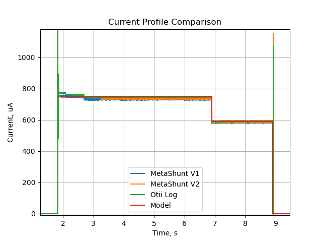
The current plot, when zoomed to the first wakeup cycle, looks like the plot below. Note that the logs have different lengths and start at different points, so they don't fully overlap.
![]()
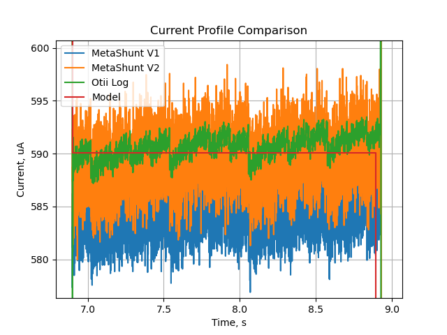
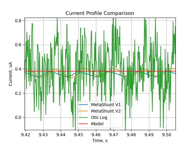
This comparison tool is helpful for evaluating between firmware updates or for comparing to a predictive model of how much power your product or project should consume. For example, you can zoom into different sections and compare data from MetaShunt to data from the model (and in this case from an Otii Arc). Note that at higher current, the Otii Arc appears to have lower noise than MetaShunt V1 and V2, but appears to be much noisier at low current below 500nA.
![]()
![]()
-
Introducing: MetaShunt V2
10/07/2024 at 12:59 • 0 comments![]()
MetaShunt V1 has been functional and available for a while now, and while it is still a wonderfully effective tool for examining the current consumption of a project across a wide range of operational modes, there were several improvements I wanted to make. This led me to develop MetaShunt V2! Thank you to my early customers on Tindie - your feedback and bug finding has helped make the original MetaShunt and now MetaShunt V2 that much better!
Goals and Updates of MetaShunt V2MetaShunt V2 was developed to fix or improve a few key features of the original MetaShunt, as well as to add a key new feature:
- The MetaShunt V2 LT Version can operate as a standalone unit, continually monitoring the total energy used by your product, project, or prototype.
- Once powered by USB, it continually measures current at the usual high rate and high accuracy used when streaming data to your computer over USB. At approximately 1Hz, it updates the onboard LCD display with the current *ahem* current, and displays the total on time in seconds and the total "current x time" in nAh, uAh, or mAh. Care is taken in the accumulation and math to ensure no overflow or underflow occurs across such a wide range of power levels.
- The accumulated data can be reset with the touch of a button.
- MetaShunt V2 provides a major step up in performance across the board.
- The internal sample/loop rate is nearly doubled to >700 kHz.
- The ADC resolution is 4X better, going from 12-bit to 14-bit.
- The burst measurements can be made 5X faster, and more data is saved during the burst read than could be before.
- The continuous data outputs are about 20% faster.
- The shunt MOSFETs have lower on-state resistance, leading to better accuracy.
- The gain stage has higher gain-bandwidth product, improving sensing bandwidth and reducing burden voltage.
- The calibration approach is very different.
- A fixed, high accuracy 50:1 amplification stage is used in the measurement path, so there are no resistors in the amplification stage that must be measured accurately and configured.
- High accuracy resistors are used in all shunt stages, to reduce the need for individual calibration of MetaShunt devices (although calibration can be performed to improve accuracy beyond a baseline).
- The physical form factor is improved.
- More care was taken on the aesthetics of the design, as well as making the outer dimensions and mounting holes fit a desired pattern. This makes it easier to incorporate into an enclosure or mount onto a test bench.
- The screw terminals are replaced by spring-pin terminals, enabling the user to swap in and out the DUT without tools.
- The programming pins are more accessible and labeled better.
- A button has been added which can be used to manually trigger burst measurements.
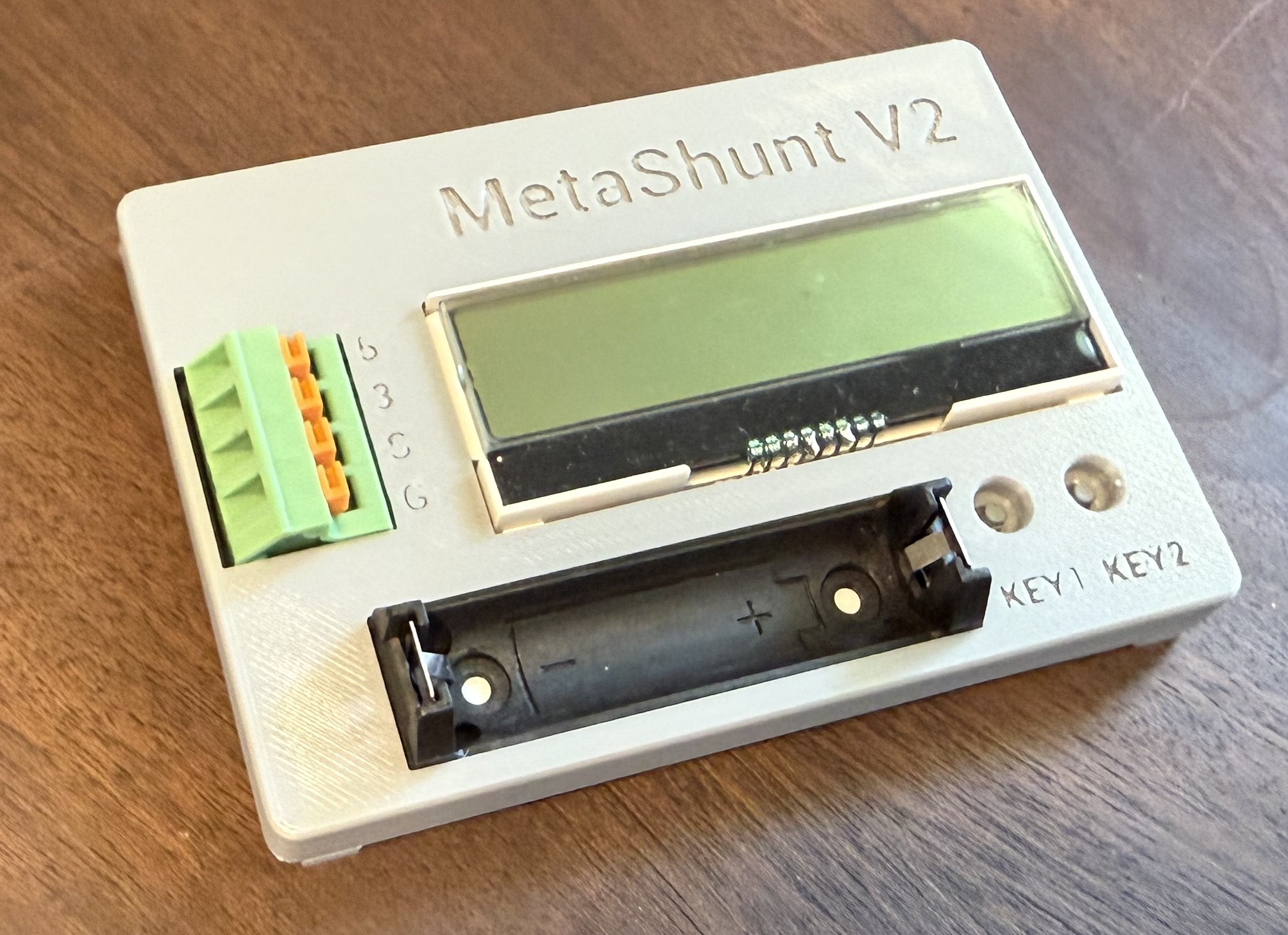
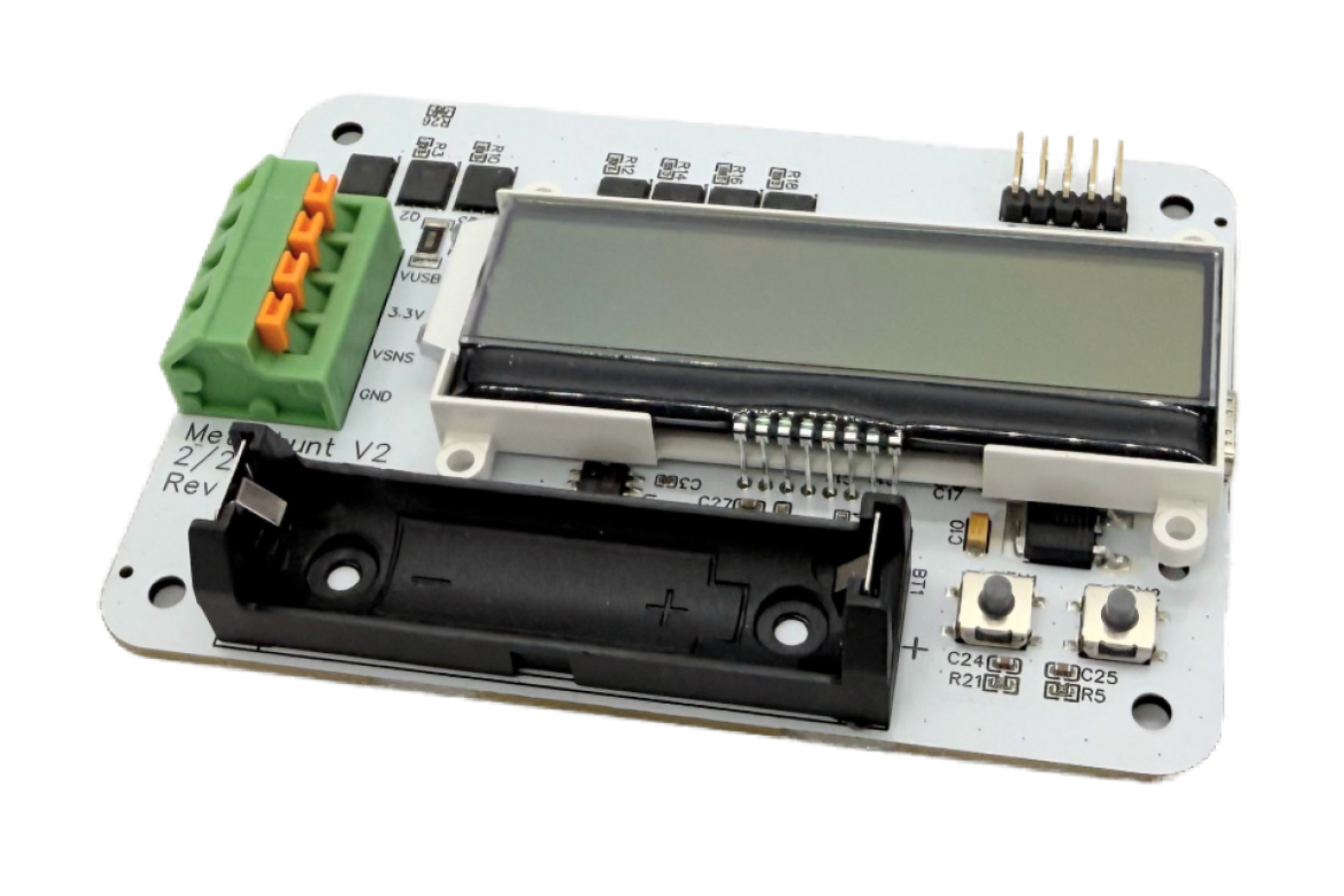
First Look at the HardwareMetaShunt V2 LT is shown below, with its new LCD display. Note also the additions of spring-lock connectors for the DUT, an improved shape, and two buttons. One button is used to reset long term data and the other is used as a trigger for burst measurements.
![]()
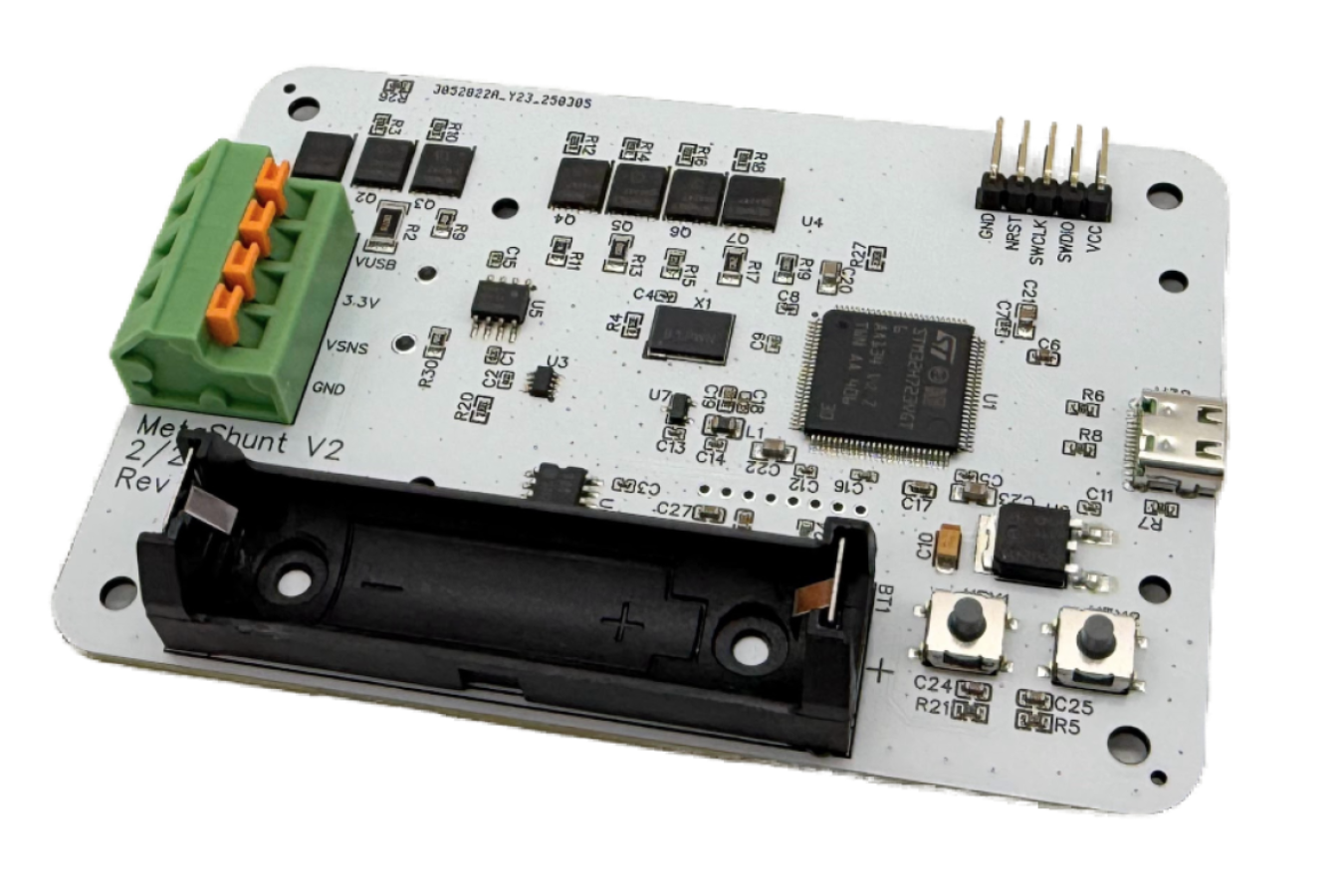
The base version of MetaShunt V2 is shown below. It has all of the features of the original MetaShunt along with significantly improved performance.
![]()
Interface UpdatesUpdates have been made to the open source MetaShunt Interface on GitHub. MetaShunt V2 is mostly backwards compatible with the original interface, but some changes were needed to support new capabilities. Specifically, check out the new realtime interface at Realtime Interface/metashunt_v2_realtime_interface.py. Also, check out the V2 version of the user guide for updates on how to use MetaShunt V2.
Available Now!MetaShunt V2 is available now on my Tindie store here! Thank you for all the support from this community!
- The MetaShunt V2 LT Version can operate as a standalone unit, continually monitoring the total energy used by your product, project, or prototype.
-
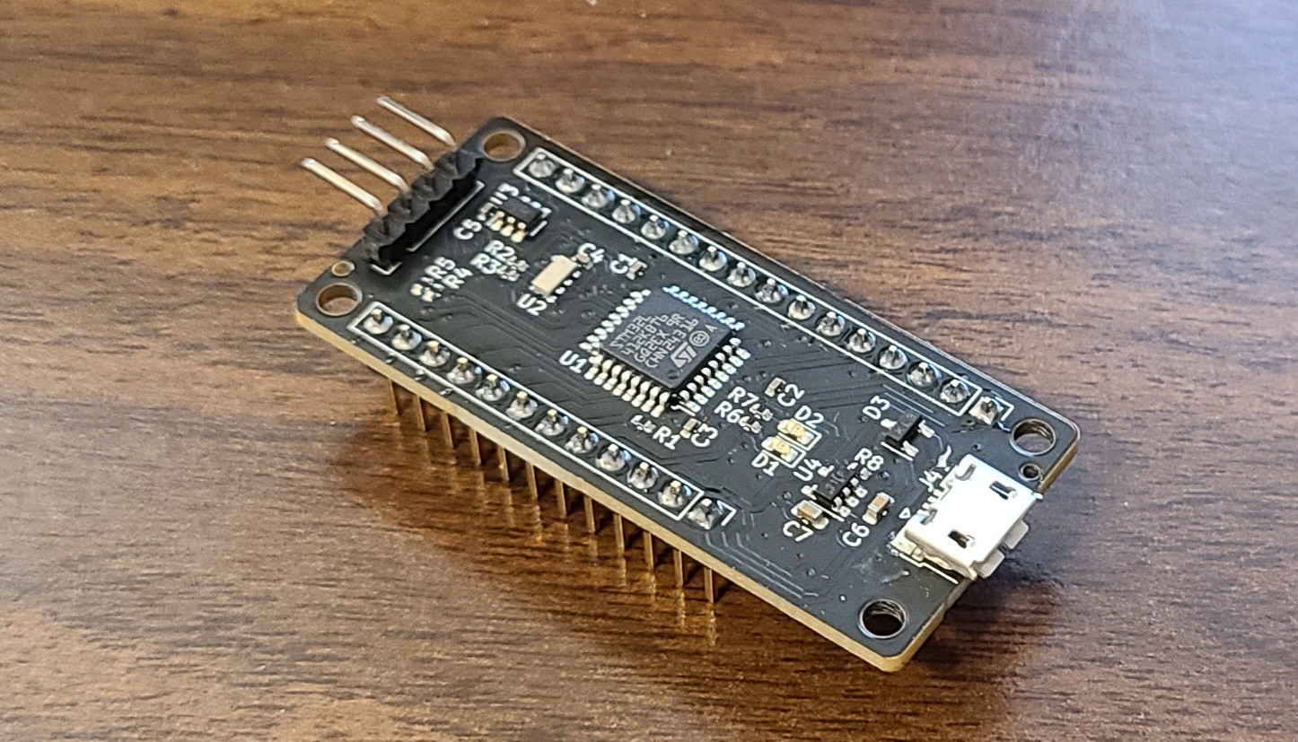
Nanosleeper - Sub 100nA Deep Sleep Dev Board
01/28/2024 at 18:24 • 0 commentsI used MetaShunt to test my new ultra-low power development board, called Nanosleeper. The goal with Nanosleeper was to achieve <100nA deep sleep current with the ability to wake up at a selected time. It was built in the Adafruit Feather form factor, but does not 100% match the Feather specification. It has support for controlling external power and I2C pullups for external devices so that very, VERY low power systems can be prototyped.
Debugging and testing a product like Nanosleeper is difficult without a tool like MetaShunt. The power used when on is over 8,000X times higher than when in deep sleep, so measuring current with a simple shunt is not likely to work. However, MetaShunt has no issues with this.
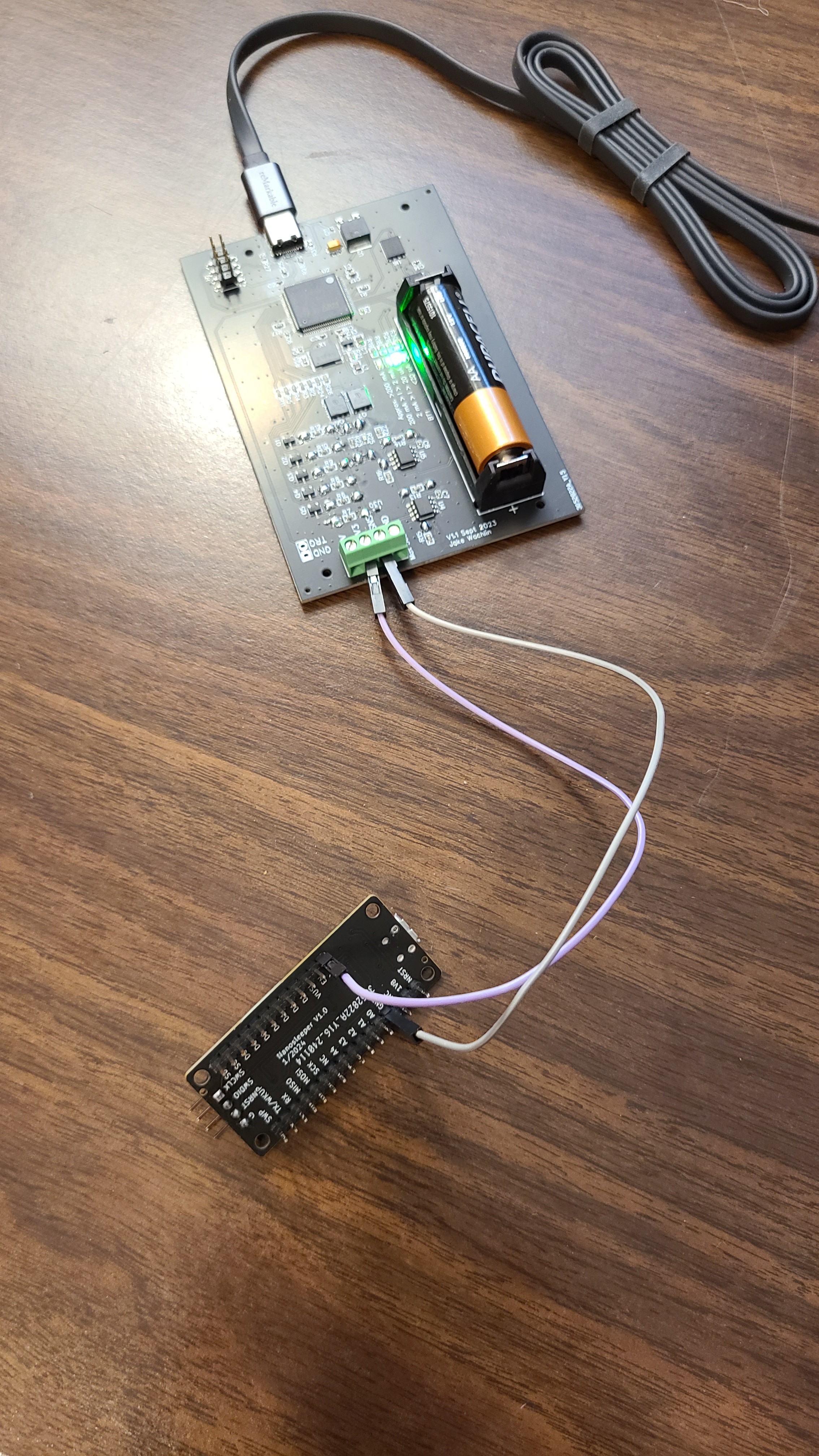
Pictures of an assembled Nanosleeper and it connected to MetaShunt are shown below. Nanosleeper is powered by the 3.3V supply from MetaShunt into the BAT input of Nanosleeper. Because Nanosleeper uses an extremely low power linear voltage regulator (1.8V logic level), this gives the same current results as it would if powered by a 3V coin cell battery.
![]()
![]()
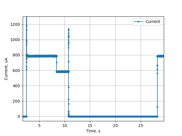
The firmware used during this test is shown below. The two onboard LEDs are turned on for 5 seconds, then turned off. A 2 second busy wait then occurs. Next, the RTC is set up using I2C, and set to wake the system after 15 seconds. The wakeup pins are then configured and shutdown sleep mode is entered.
  // Toggle LED to indicate awake
  HAL_GPIO_WritePin(D12_GPIO_Port, D12_Pin, GPIO_PIN_SET);
  HAL_GPIO_WritePin(D13_GPIO_Port, D13_Pin, GPIO_PIN_SET);
  HAL_Delay(5000);
  HAL_GPIO_WritePin(D12_GPIO_Port, D12_Pin, GPIO_PIN_RESET);
  HAL_GPIO_WritePin(D13_GPIO_Port, D13_Pin, GPIO_PIN_RESET);
  HAL_Delay(2000);

  // Set up RTC, checking if it's already been set up
  bool is_initial_setup = true;
  uint32_t current_time_utc = 1705968815;
  bool rv_3028_setup_ok = init_rv_3028_c7(hi2c1, current_time_utc, is_initial_setup);


  // Go to shutdown mode, with pin wakeup.
  HAL_PWR_DisableWakeUpPin(PWR_WAKEUP_PIN1);


  /* Enable wakeup pin WKUP1 */
  HAL_PWREx_EnableGPIOPullDown(PWR_GPIO_C, PWR_GPIO_BIT_14);
  HAL_PWREx_EnableGPIOPullDown(PWR_GPIO_C, PWR_GPIO_BIT_15);
  HAL_PWREx_EnableGPIOPullUp(PWR_GPIO_A, PWR_GPIO_BIT_0);
  HAL_PWREx_EnablePullUpPullDownConfig();
  HAL_PWR_EnableWakeUpPin(PWR_WAKEUP_PIN1_LOW);
  HAL_PWREx_DisableInternalWakeUpLine();

  /* enter shutdown */
  __HAL_RCC_PWR_CLK_ENABLE();
  __HAL_PWR_CLEAR_FLAG(PWR_FLAG_WUF1);
  HAL_PWREx_EnterSHUTDOWNMode();
Each of those sections of the firmware are very clear in the power profile below. The system starts up (the current spike off the chart is due to plugging in Nanosleeper to power) and with both LEDs on the current is steady at about 800uA. With the LEDs off, the current drops to about 600uA. There is a current spike to about 1.15mA during the I2C communication with the RTC, and then the system goes into deep sleep. After 15 seconds, the system starts up again and turns on the LEDs.
![]()
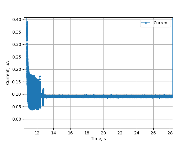
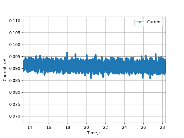
The deep sleep current is shown in higher detail below, and is steady just under 95nA.
![]()
![]()
This example shows MetaShunt's performance for an ultra-low power design, with ~8,000X variation in power consumption during operation.
MetaShunt: High Dynamic Range Current Measurement
A low-cost and accurate tool for analyzing the power consumption of ultra-low power and IoT devices with rapidly changing current usage