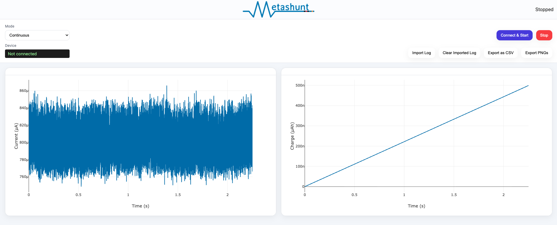
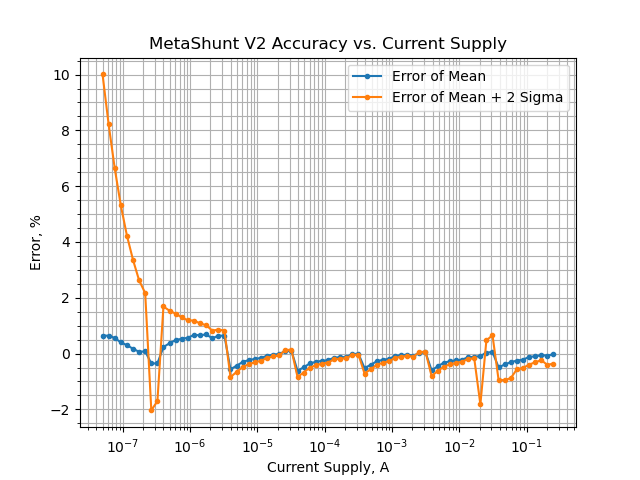
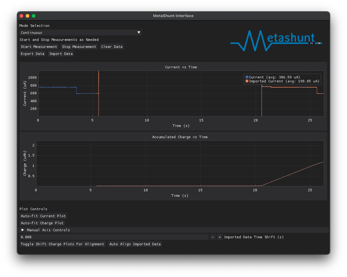
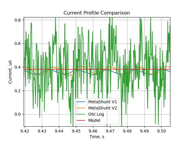
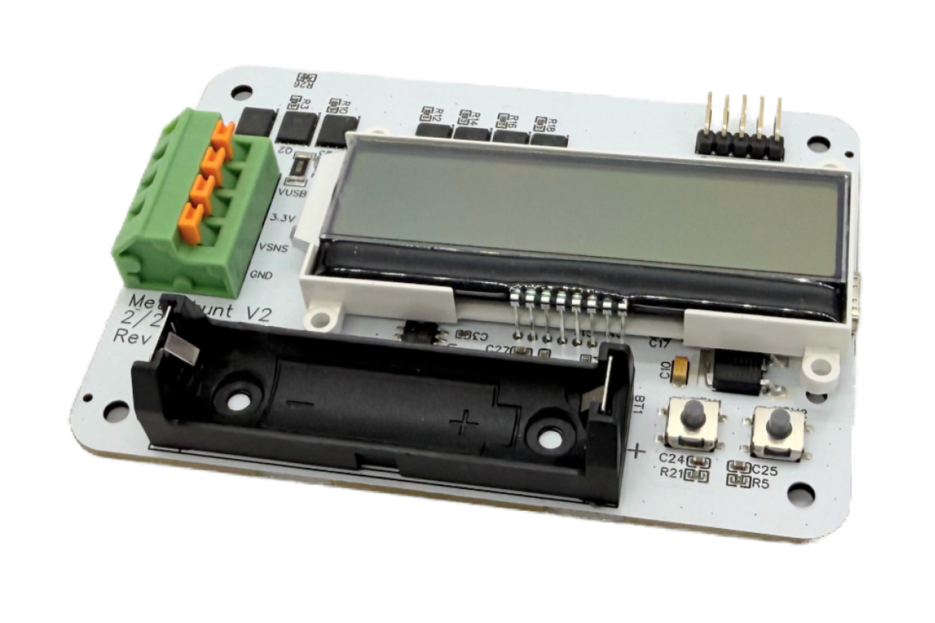
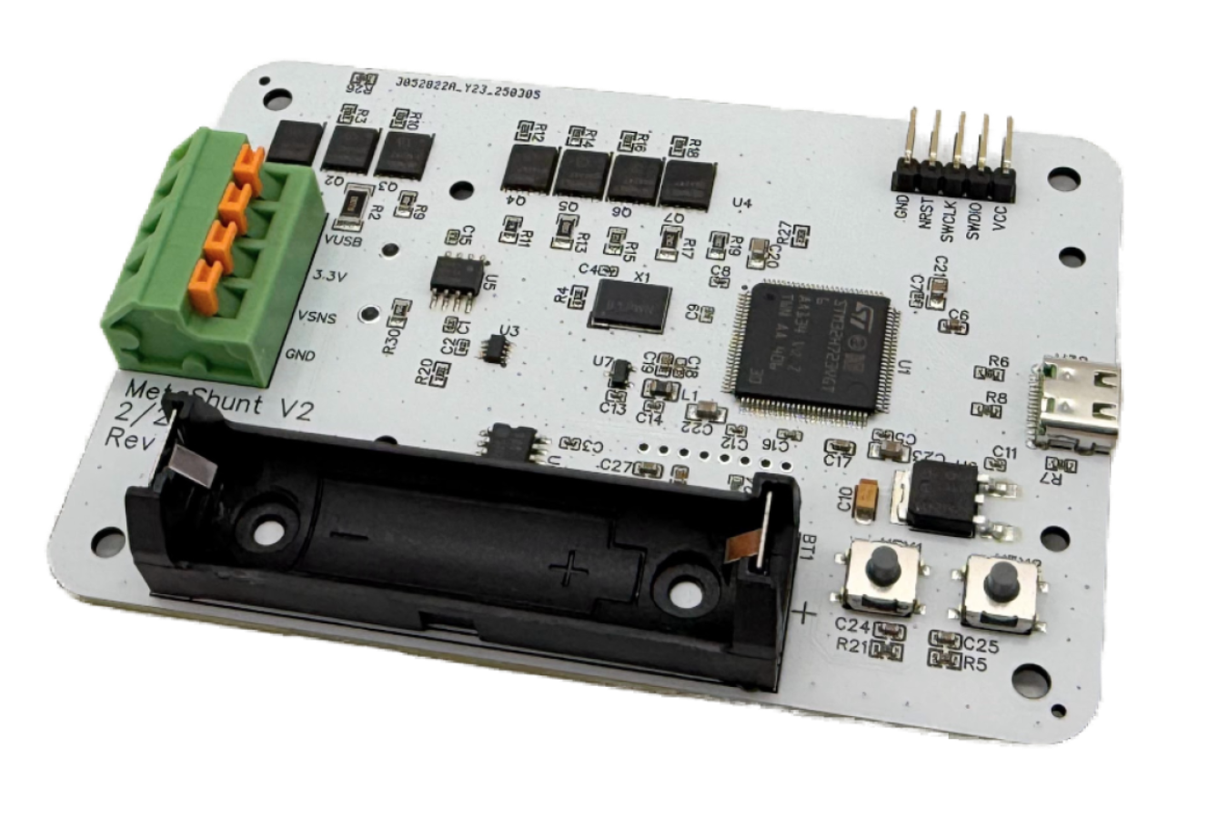
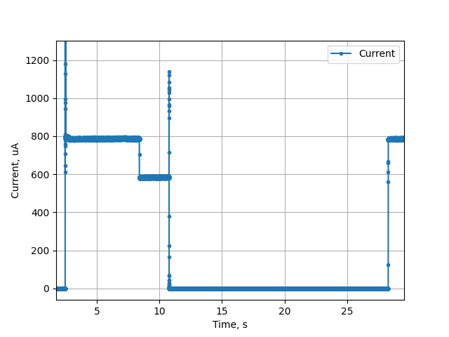
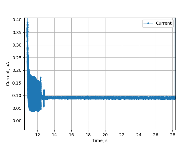
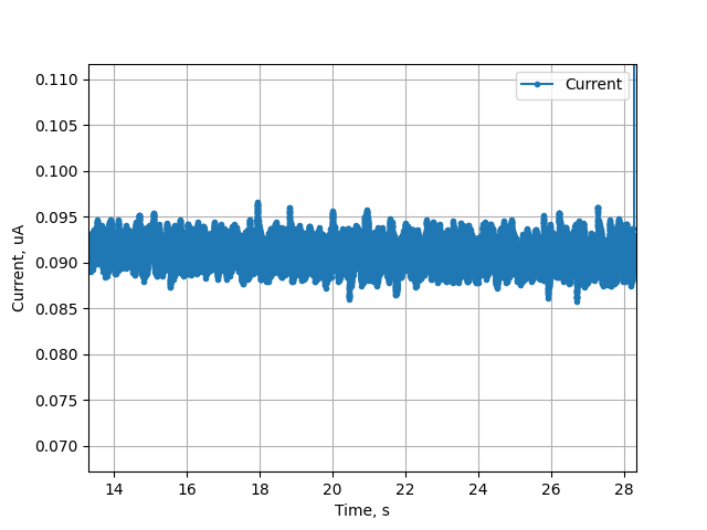
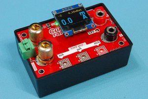
MetaShunt leverages a simple idea - by quickly and accurately measuring the voltage across a current shunt resistor and engaging additional shunt stages when needed, MetaShunt ensures that it can provide accurate current measurement across a range of approximately 10,000,000:1 (from 50nA to 1,500 mA) without providing significant voltage burden. This range of current is specifically targeted for use with ultra-low power and IoT systems. By measuring current rapidly over time, the total energy use during a given portion of your code can be determined. MetaShunt acts as a virtual ground for your system, so that you can use your battery. Or, MetaShunt can provide 3.3V or 5V to the system under test if desired.
Q: Why do you need this tool?
- You are developing low power electronic projects, and need to know how much power you are using during short wake-up cycles
- You develop IoT systems, and the power consumption changes drastically during data transmission and you want to measure it
- You are testing components to validate them against the datasheet, and the current is lower than your multi-meter can measure reliably
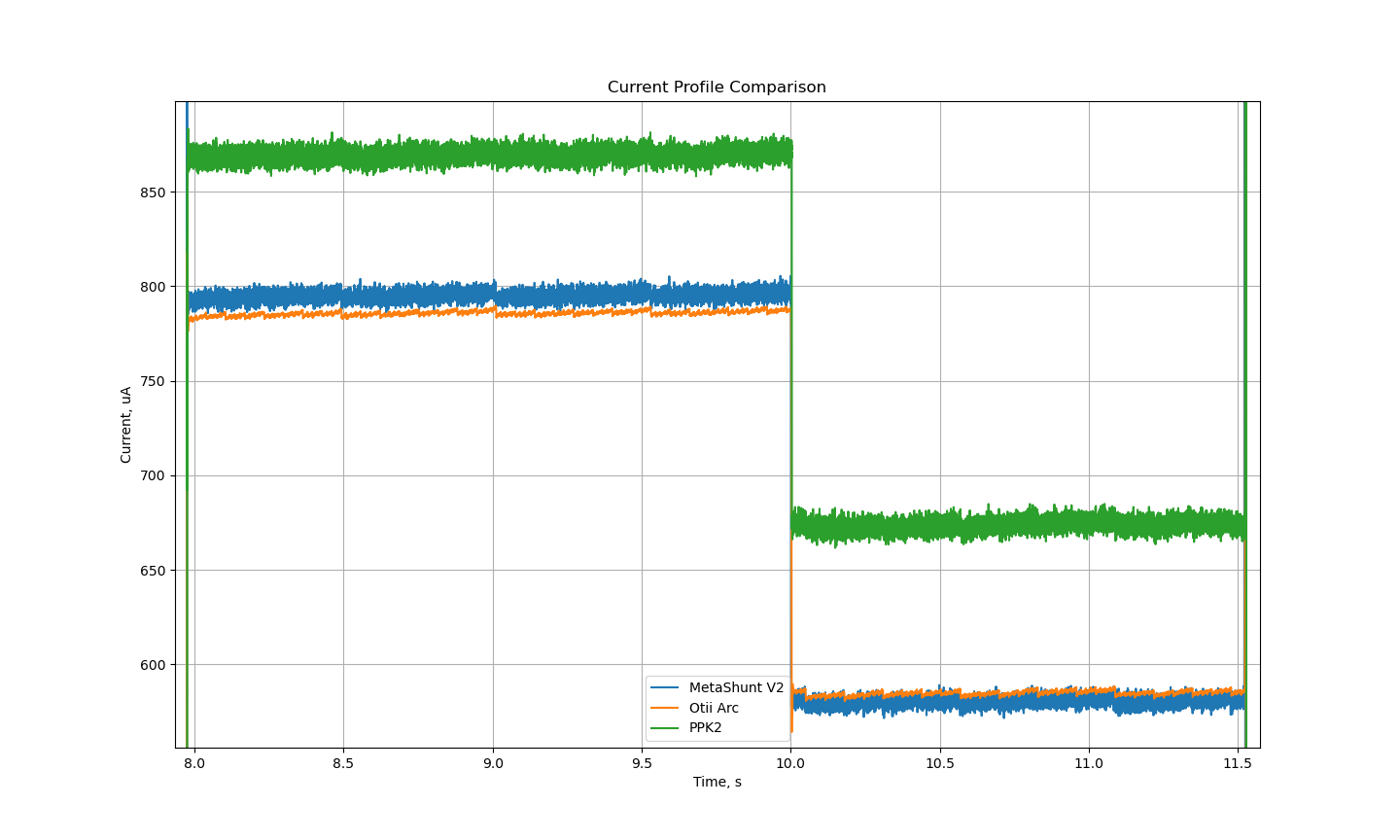
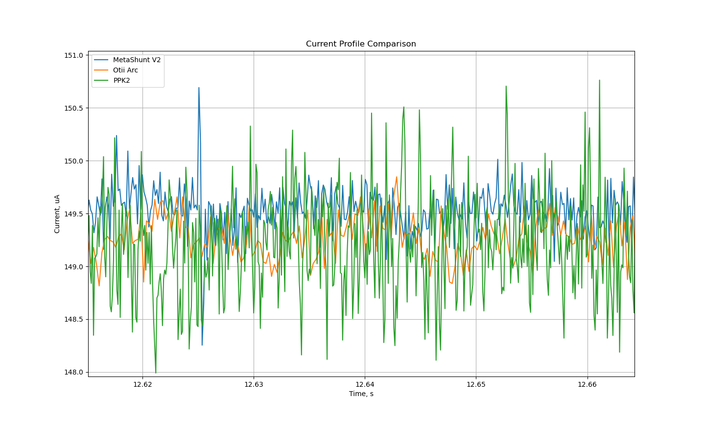
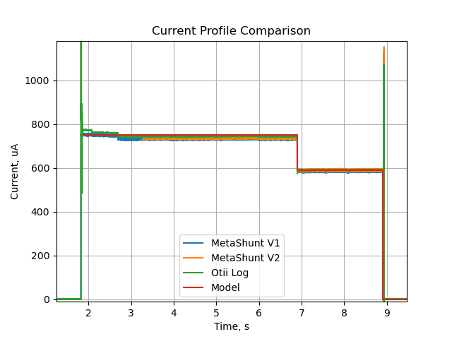
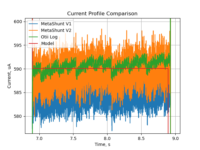
Q: Isn't this basically a JouleScope or Otii Arc?
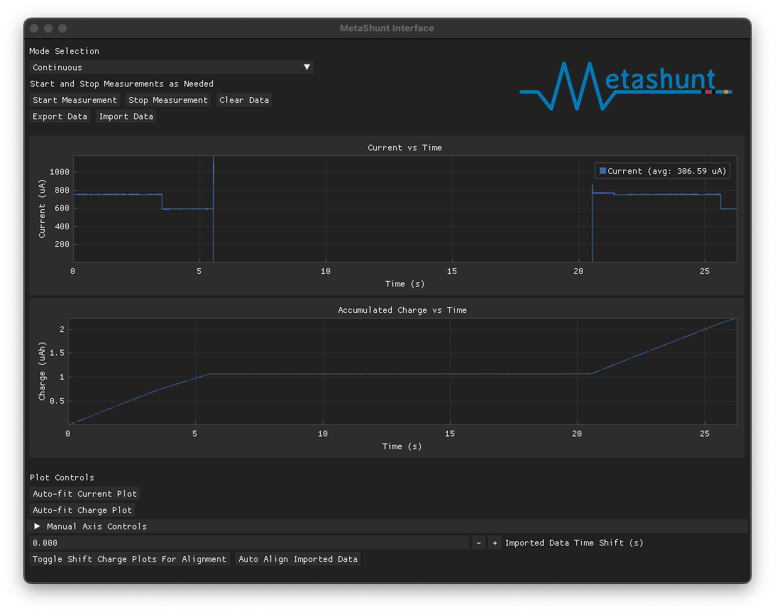
Yes, it is designed for very similar use, but does have significant differences. MetaShunt is designed more for DIY hobbyists than those products are, and that can be seen in price, capabilities, and openness. MetaShunt has an open USB serial interface protocol and example Python interfacing scripts so that users can build their own testing scripts with it. There are no subscriptions or features behind paywalls.
Q: Can I buy one?
Yes! It is available in Tindie here!


 Bertrand Selva
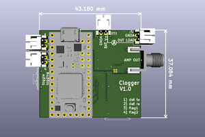

 Jan Waclawek
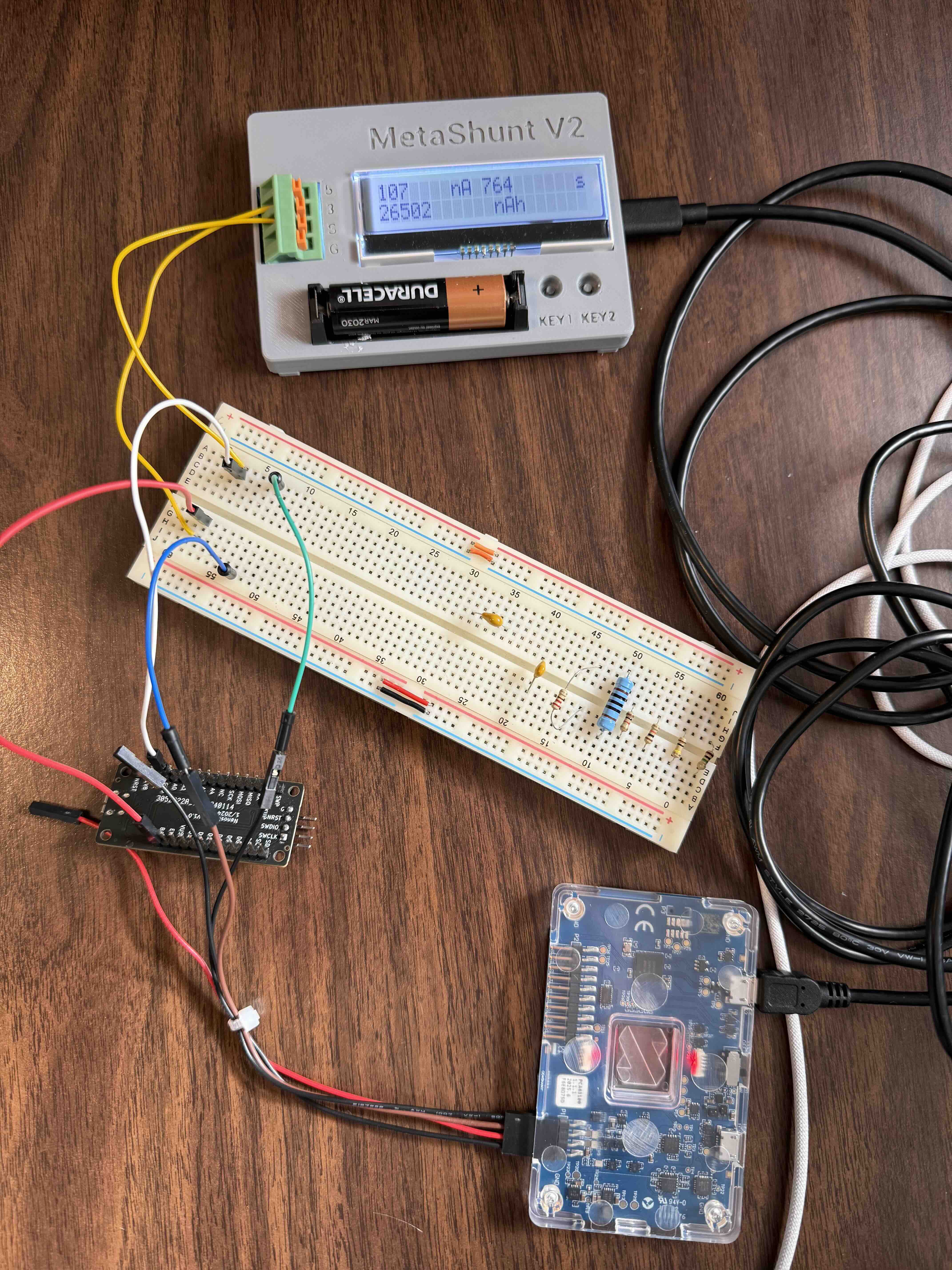
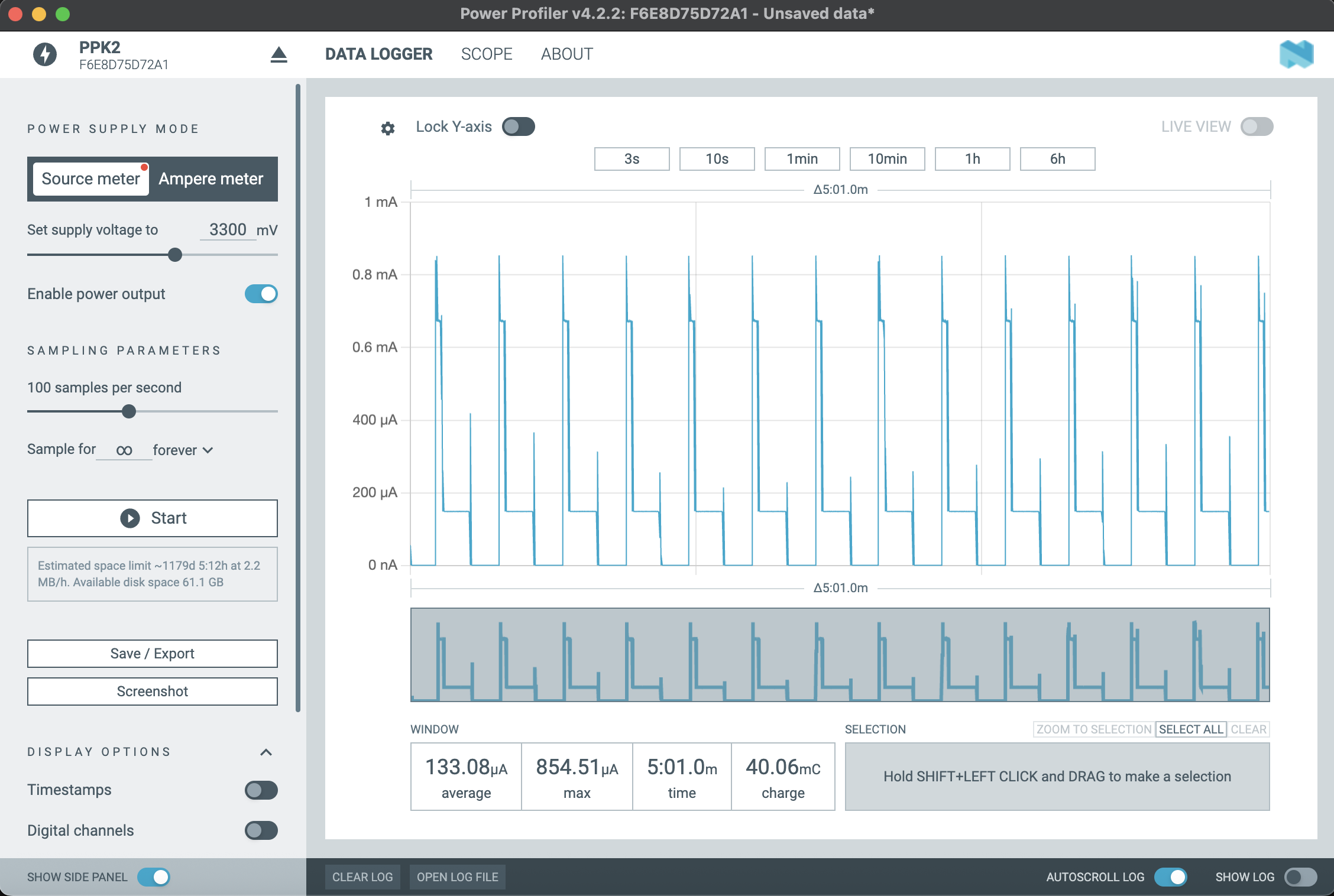
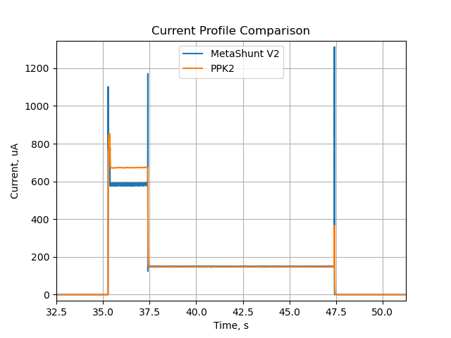
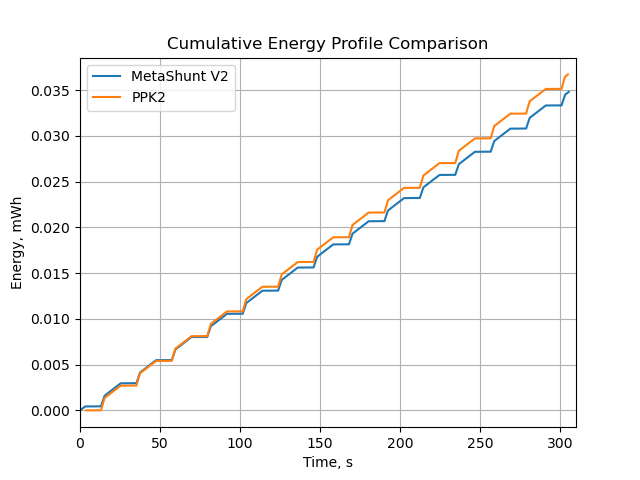
I'm certainly looking forward to Metashunt being available on Tindie. I wonder how this compares to Nordic's Power Profiler Kit II which is another hobbyist-friendly (<$100) current measurement tool.
What's nice about the PPK2 is that it can supply an arbitrary voltage to the target (0.8V-5V) and also that it has digital inputs, so that you can easily attribute a measured current to a certain device state using GPIOs.