-
Codebase Bulldozed - Reset & Pivot!!!
12/14/2024 at 02:08 • 0 commentsI recently acquired a new Fluke 8840A DMM. Sadly, I learned its unconventional command formatting would require some significant tweaks to my existing codebase; moreover, these tweaks would bloat with every new device I have to implement. At least the new devices that have some unconventional setup requirements. Hindsight is 20/20, so I decided to bulldoze my entire repo and start again from scratch. This time trying to emphasis an instrument-agnostic system.
As a reminder I’d like this module to support common instruments such as power supplies, e-loads, oscilloscopes, DMM’s and function generators for starters. I’d like to add some more exotic instruments at a later date, but these are my targets for first release.
To create an instrument-agnostic system, requires some amount of upfront effort to add support for each instrument. This configuration will come in the form of small json config files for each instrument. Each instrument will have several basic methods that should be filled out, dependent on what type of instrument it is. Here’s an example json file for my SPD1168 power supply. The user must fill out the string to be sent to the device to accomplish each function. Some functions may not be supported such as “set_remote_sense”. In cases like this the command can be left blank. On my current version of the project, this will raise a warning, but won’t halt the process.
{
    "Manufacturer": "Siglent",
    "DeviceType": "Power Supply",
    "channels": 1,

	"init": [""],
    "reset": ["*RST"],
    "operation_complete":["*OPC?"],

    "set_output_en": ["OUTP CH{channel},ON"],
    "set_output_dis": ["OUTP CH{channel},OFF"],

    "set_voltage": ["CH{channel}:VOLT {value}"],
    "set_current": ["CH{channel}:CURR {value}"],
    "set_remote_sense": [""],

    "get_voltage":["CH{channel}:VOLT?"],
    "get_current":["CH{channel}:CURR?"],

    "meas_voltage": ["MEAS:VOLT? CH{channel}"],
    "meas_current": ["MEAS:CURR? CH{channel}"],
    "meas_power": ["MEAS:POWE? CH{channel}"]
}
Here's a short example of the eload class test script. I’ll be refining the codebase some more this weekend and hopefully making in public (though still prerelease).
# ================ Electronic Load Test ================ elif( device_type == DeviceType.ELOAD): myEload = ELOAD(USER_Eload_ip, ConnectionType.Ethernet) print("====================================================\n" "==================== ELOAD TEST ====================\n" "====================================================\n") # Toggling the output - errr. I guesss input in this case ;) - print("Enable Eload Output") myEload.set_output_dis(Channel.CH1) sleep(0.5) myEload.set_output_en(Channel.CH1) sleep(0.5) # Test Constant Current test_load = round(random(),2) print("\nTest CC mode @"+str(test_load)+"A") myEload.set_mode_type(EloadMode.CC, Channel.CH1) myEload.set_load_value(test_load, Channel.CH1) # Check if set set_value = myEload.get_load_value(Channel.CH1) if(set_value == test_load): print("PASS") else: print("FAIL -> Read "+ str(set_value)) # Test Constant Resistance test_load = round(random()*100,2) print("\nTest CR mode @"+str(test_load)+" Ohm") myEload.set_mode_type(EloadMode.CR, Channel.CH1) myEload.set_load_value(test_load, Channel.CH1) set_value = myEload.get_load_value(Channel.CH1) if(set_value == test_load): print("PASS") else: print("FAIL -> Read "+ str(set_value)) # Test Constant Power test_load = round(random(),2) print("\nTest CP mode @"+str(test_load)+"W") myEload.set_mode_type(EloadMode.CP, Channel.CH1) myEload.set_load_value(test_load, Channel.CH1) set_value = myEload.get_load_value(Channel.CH1) if(set_value == test_load): print("PASS") else: print("FAIL -> Read "+ str(set_value)) # Test Constant Power test_load = round(random(),2) print("\nTest CV mode @"+str(test_load)+"V") myEload.set_mode_type(EloadMode.CV, Channel.CH1) myEload.set_load_value(test_load, Channel.CH1) set_value = myEload.get_load_value(Channel.CH1) if(set_value == test_load): print("PASS") else: print("FAIL -> Read "+ str(set_value)) # Please for the love of god, use remote sense if your doing efficiency sweeps print("\nEnable Remote Sense") myEload.set_remote_sense(1, Channel.CH1) # How to measure V/I/P print("\nMeasure Voltage, Current, and Power") volt = myEload.meas_voltage(Channel.CH1) curr = myEload.meas_current(Channel.CH1) power = myEload.meas_power(Channel.CH1) print("Voltage -> " + str(volt) +"V") print("Current -> "+ str(curr) +"A") print("Power -> "+ str(power) +"W") -
BJT Plotter - The How?
04/22/2024 at 05:22 • 0 commentsOverview
As mentioned in my last log, I had an issue where I “needed” to explain why a current mirror wasn’t working as expected. I thought I had helped solve a colleague’s issue, but it turned out to a be red herring… now their current mirror was using Onsemi FMBA06 (for those playing along at home) and still performing terribly.
Two birds one stone. I decided I’d try to root cause the issue and learn lab automation at the same time. I knew my equipment could be programmed but wasn’t sure how. Luckily, I quickly found PyVisa1, and spun up a BJT Plotter2 over a weekend.
Note 1 - If you have some new-ish lab equipment likely supports SCPI… I strongly recommend you give this python package a try. Its freaking phenomenal!
Note 2 – Yes, I’m aware you could accomplish similar results with a function generator and an oscilloscope in XY mode… let me cook!
Setup
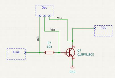
The test setup is shown below… I should REALLY replace my Oscilloscope with a bench DMM (insert “if I had one meme”). The function generator is used as a DC supply capable of 1mV steps. I have to use a fairly large base resistor to squeeze out any accuracy I can from my scope. The scope then measures the current into the base, as well as the voltage Vce, swept by the PSU.
![]()
Scripting - Set Ib & Sweep VCE
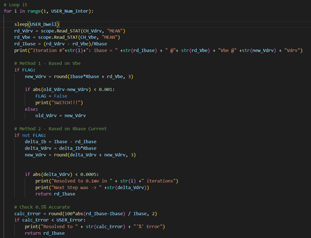
The script should be as easy as (1) set Ib, then (2) sweep Vce? And yup it’s that easy. Shown below is the main for loop of the BJT Plotter script.
![]()
To set the base current I use the Set_Ibase function shown below. It first assumes Vdrv = Ib*Rb-Vbe, then it sets the function generator to output Vdrv, and measures the true Vbe. Vdrv can then be recalculated, and the process can be repeated. I found that this method quickly converged to its final value, but since Vbe is so small it’s difficult to converge to the CORRECT value.
The second method is to assume Vbe is constant, and then focus on the desired change in base current. This way we’re not dealing with tiny changes in voltages (below 1mV in the case of Vbe), and I can focus on the somewhat large voltage across Rbase.
![]()
Here’s an example of the 2-stage algorithm working. Notice that iteration 2 and 3 measured IDENTICAL Vbe. I need a much more accurate/precise instruments to use method 1 by itself.
![]()
Final Result
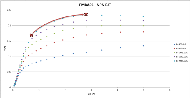
Sweeping the part revealed the following curves… Gross! At higher currents the knee of the saturation region stretches out much further than I expected. We can imagine the two transistors in the current mirror as the X’s on the 500uA curve. The left X would be the load setting BJT, and the right X would be the sinking/sourcing BJT. The left X is locked to Vbe(on), but the right X will see Vce varied with load. Clearly this current mirror won’t work great, and it doesn’t!
![]()
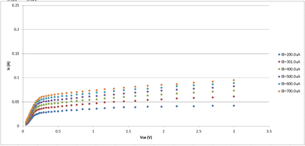
A quick sanity showing the BJT plotter on a well-documented part (2n3904). Curves look good!
![]()
TLDR - Onsemi FMBA06 makes for a poor current mirror at my operating point.
-
BJT Plotter - Why?
11/20/2023 at 02:24 • 0 commentsWhy? Fair question… this plotter was the fallout of 2 converging topics. (1) Recently I was debugging a current mirror and was frustrated that there were no IV curves on the BJT’s datasheet, and (2) I’ve been meaning to find an excuse to start automating my lab.
The Humble Current Mirror…
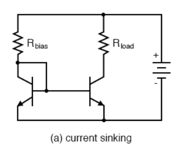
As a reminder the basic current mirror that was drilled into my head through university is shown below. The key idea of this design is that the base-emitter voltage drop is mirrored by both transistors. If the two parts are well matched this should lead to identical base current, and thus similar collector current (Ic = B*Ib). The current across Rload is set by changing the value of Rbias…. Current = (Vcc-0.6)/Rbias.
![]()
Current Mirror Woes…
While debugging a circuit at work, I started to think about this design a bit more critically… and came to the realization “WOW the generic current mirror sucks!” Or at least, you NEED to look very closely at the BJT pair you’re using. Let’s go over the common issues with this circuit, hopefully when I inevitably run into another of these in the future, I’ll know the red flags.
First and most common issue is BJT matching. This issue can be explained by (Ic = B*Ib)… since Vbe should be mirrored, we’ll assume Ib is too. In this case, Ic will be directly proportional to the gain beta. Any error in beta between these two transistors result in an error of our expected collected current. If we look at the datasheet for a jellybean npn BJT we see a wide spec for min/max gain (100/300).
![]()
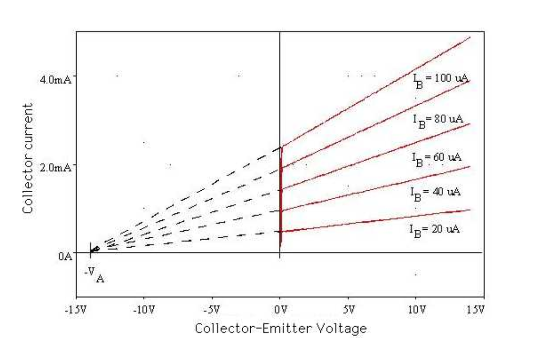
Next issue, the early effect! The early effect shows itself as a gradual increase in collector current as Vce is increased (see below). We previously mentioned our leftmost transistor has its Vce “locked” around 1 diode drop, but the right one is meant to maintain its current regardless of Vce… Clearly, looking at the graph below, collector current is still a function of collector-emitter voltage!!! If we want our current mirror to function well, we want the Early Voltage "Va" to be as large as possible. Otherwise, we’ll see a sizeable error that is dependent on Vce.
![]()
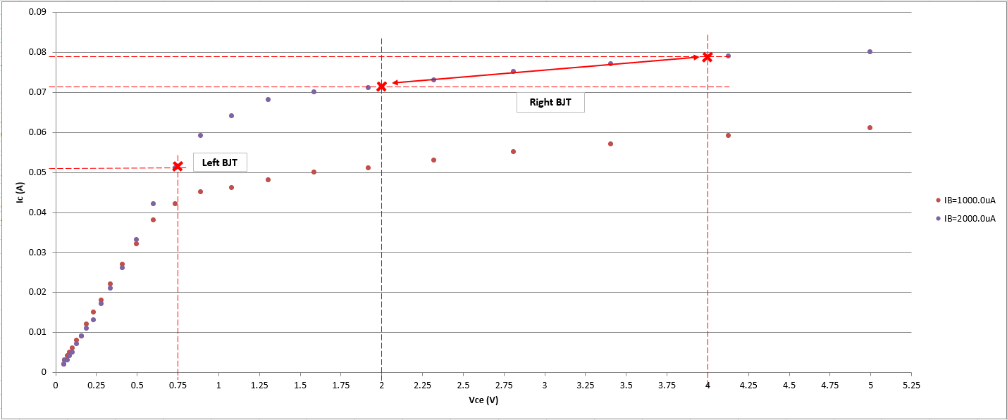
Last issue, is the operating point of the leftmost transistor. We know that Vce will be locked near 0.6V, what happens if the left transistor is in saturation while the right is active? See an example below (taken from Nexperia BCM56DSF)… If I used a BCM56DSF based current mirror set to 50mA, it seems like one part will be operating in the “knee region” (errr saturation) while the other would be comfortably in the active region. We expect the two set points to be along the same Ib “curve” of this BJT characteristic, see below. We can avoid this problem, with our transistor (low saturation voltage) & setpoint.
Note: I couldn't find any mention of this "issue" with current mirrors online, so maybe I'm missing something here... take my last gripe with a pinch of salt
![]()
TLDR - Don't use a half baked Current Mirror in your circuit.
- Gain Errors, Early Effect, Ensure both BJT's in active region
LabAssistant - SCPI pyVISA
Oh Boy this project has grown since I started.... big update coming this weekend.
 Jesse Farrell