Bitmerse LLP
-
Enabling Broadcast Mode on WiSer
03/01/2024 at 11:19 • 0 commentsWe're enabling Broadcast Mode on WiSer! This significant upgrade opens up a world of possibilities for users with multiple host systems and embedded devices in their environment.
So what does it do? The Broadcast Mode in WiSer enables wireless serial communication between multiple devices without the need for physical cables, creating a cable-free network for data transmission. It’s a convenient and efficient way to establish wireless serial communication links between all the various host systems and embedded devices in your environment.
How it Works
- Each host system or embedded device connects to one WiSer-USB or WiSer-TTL device
- Every host system or device now has a functional serial port, allowing them to broadcast data to all other connected devices
In Action
Imagine you have a total of eight host systems and embedded devices – let’s say four PCs, one Android Tab, and three embedded devices with serial interfaces. For this scenario, you’ll need five WiSer-USB devices (for the PCs and Android Tablet) and three WiSer-TTL devices (for the embedded devices).
Connect these WiSer devices to their compatible counterparts and seamlessly start broadcasting messages between all your host systems and devices. It’s that simple!
![]()
Enabling Broadcast Mode
To enable Broadcast mode, you need to tweak a simple macro in the config.h file and upload the new firmware to your devices.
#define CONFIG_ESPNOW_BROADCAST_ENABLE 1
NOTE: By default, WiSer devices are equipped with firmware that includes pre-paired devices, facilitating secure point-to-point wireless serial communication with data encryption enabled. Please be aware that Broadcast mode is disabled by default.
Choosing the Right Kit
For the example scenario mentioned above, you can use five Host-to-Client WiSer Kits, each kit includes one WiSer-USB and one WiSer-TTL devices. You can create combination of Host-to-Client kits and Host-to-Host kits according to the number of host systems and devices available in your environment.
Technical Considerations
- If your application runs solely on host systems like PCs or Linux/Android devices, opt for the required number of the Host-to-Host WiSer kits.
- Theoretically, there are no limitations on the number of devices in Broadcast mode.
- Enabling Broadcast Mode disables internal encryption in WiSer devices. However, you can always add encryption and device filtration in your application code.
With Broadcast Mode enabled on WiSer, there are so many possible application ideas we can think of, such as smart agriculture, home automation, industrial automation, environmental monitoring, education, or healthcare.
Stay tuned for more insights and updates on WiSer project!
-
Wireless Serial Communication Between Two Host Systems using WiSer
01/12/2024 at 13:02 • 0 commentsIntroduction
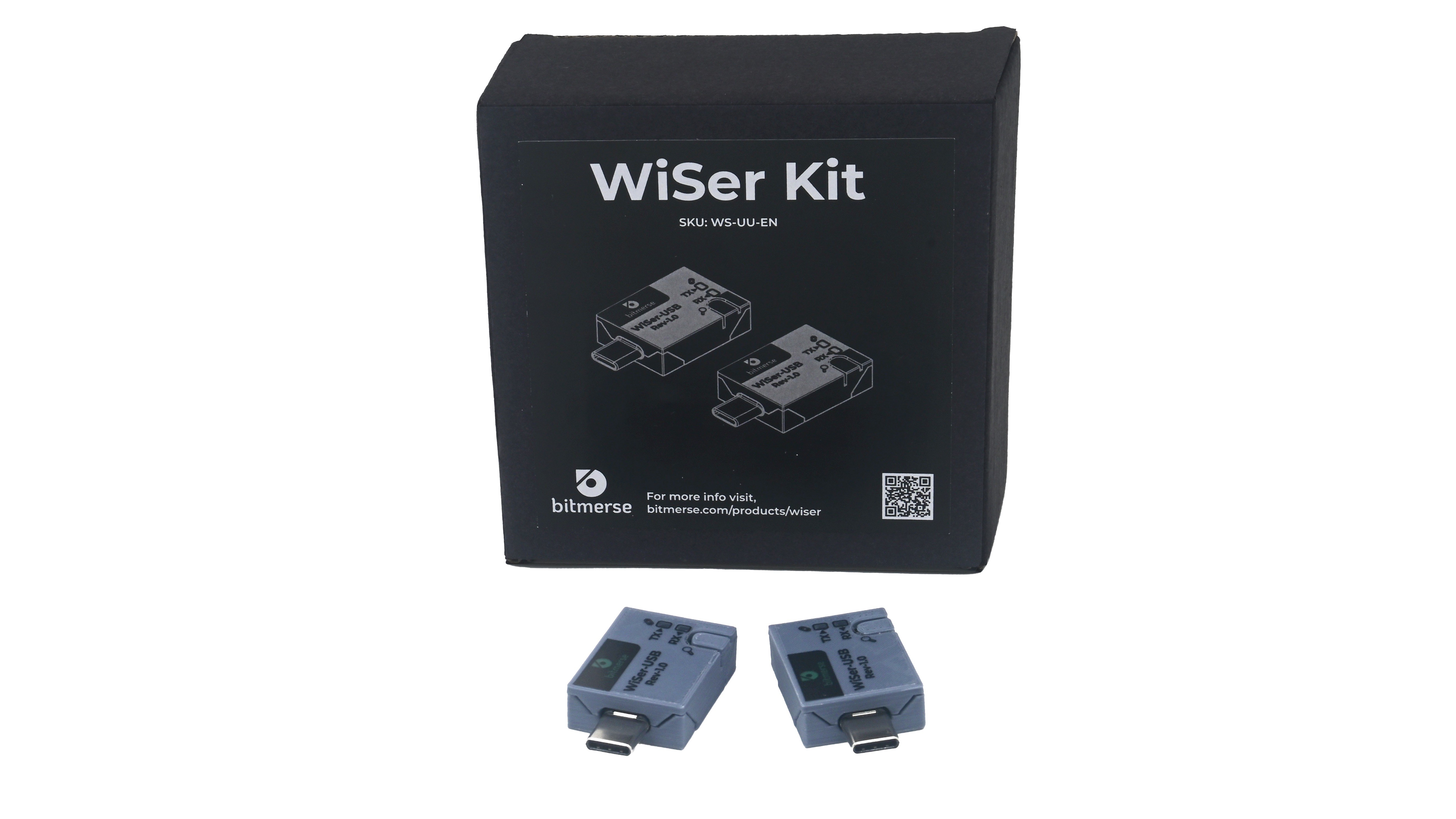
Welcome to the project log for WiSer WS-UU-EN, where we explore the capabilities of the WS-UU-EN variant. Unlike traditional WiSer configurations, WS-UU-EN facilitates communication between two host systems, providing a versatile solution for various applications.
Overview
- Variant: WiSer WS-UU-EN (comes with 2 WiSer-USB paired devices) For more information about WiSer SKU variants, please visit WiSer Product Manual.
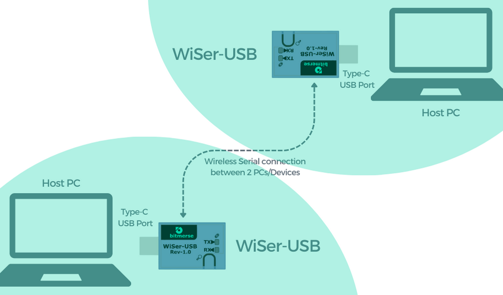
- Objective: Establish a wireless serial connection between two host systems.
![]()
Step 1: Setting Up WiSer WS-UU-EN
- Connect WiSer-USB to Host System A
- Plug the WiSer-USB device into the USB port of Host System A.
- No additional drivers or software installation needed; it’s a plug-and-play setup.
- Connect WiSer-USB to Host System B
- Similarly, plug another WiSer-USB device into the USB port of Host System B.
![]()
Step 2: Initiating Communication between Two Host Systems
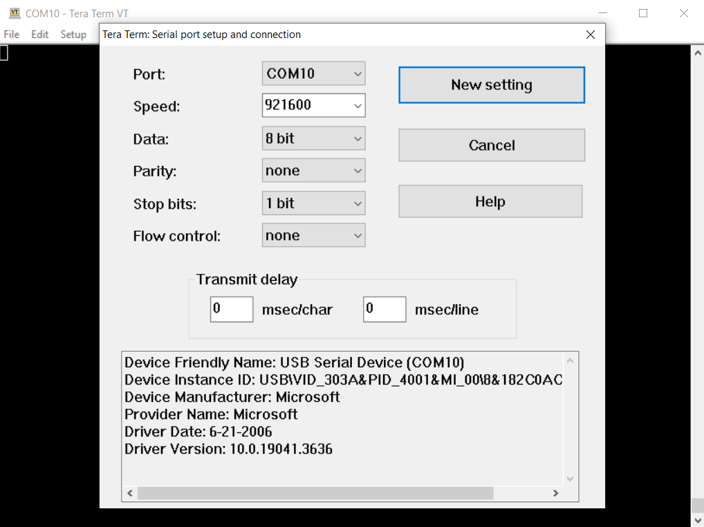
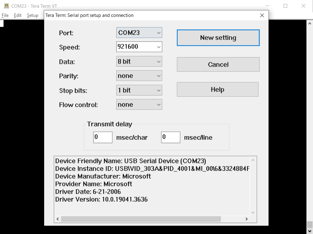
- Terminal Configuration on Host System A:
- Configure the terminal software on Host System A to use the virtual COM port created by WiSer-USB.
![]()
- Terminal Configuration on Host System B:
- Similarly, configure the terminal software on Host System B to use the virtual COM port created by the second WiSer-USB device.
![]()
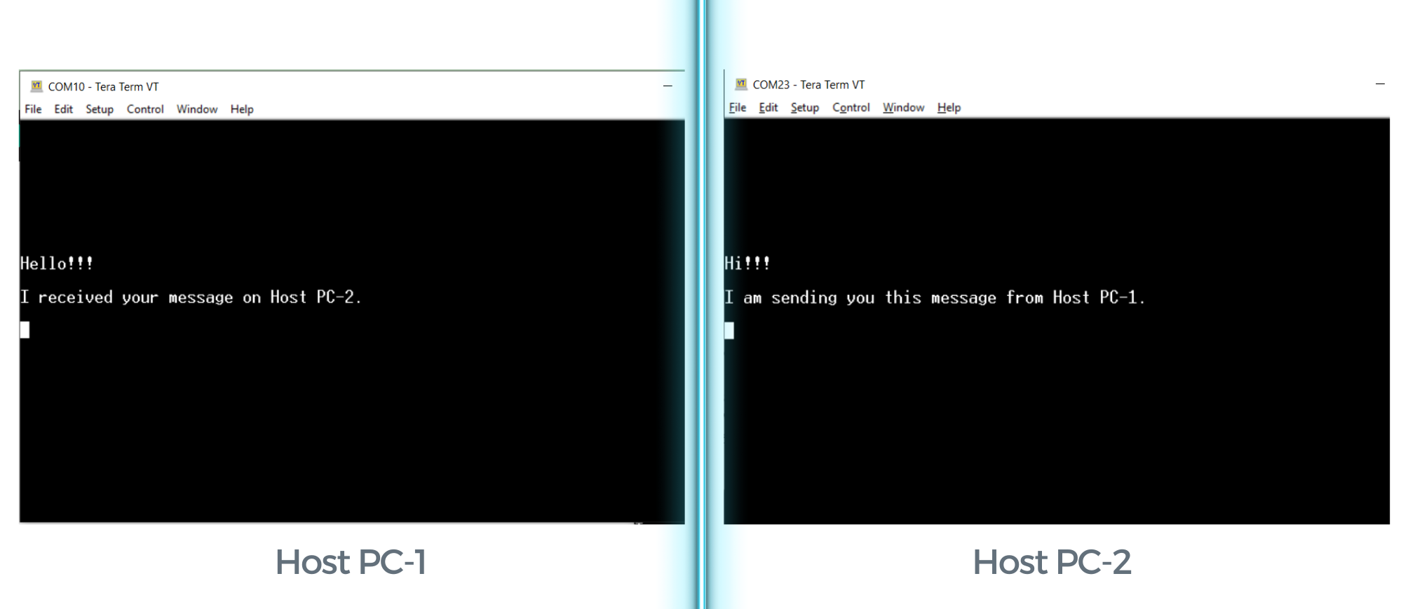
- Begin Serial Communication between 2 Host Systems:
- You can now initiate serial communication between Host System A and Host System B wirelessly using WiSer WS-UU-EN.
![]()
Conclusion
WiSer WS-UU-EN extends the flexibility of wireless serial communication to dual-host scenarios, offering a hassle-free solution for collaborative work, data transfer, and testing. Explore the possibilities of WiSer WS-UU-EN in your multi-host setups!
Stay tuned for more insights and updates on WiSer projects!
-
Functionality of the 'Find Pair' Button on WiSer
12/19/2023 at 07:54 • 0 commentsThe 'Find Pair' button on WiSer-USB device is not just about locating your paired WiSer devices; it holds additional functionalities, such as toggling the RTS/CTS hardware flow control. Let's discover the workings of the 'Find Pair' button.
- Identifying Paired WiSer Devices
WiSer provides a way to identify paired device, especially in scenarios where multiple WiSer device pairs are in use. A short press of the 'Find Pair' button initiates the identification mode. During this mode:- Indicator: The CONN LED on both paired WiSer devices illuminates steadily for 5 seconds.
- Purpose: This serves as a quick and efficient means to distinguish between paired WiSer devices, ensuring you're connected to the right one, especially when dealing with multiple device pairs.
![]()
- Enabling RTS/CTS Hardware Flow Control
For reliable data transmission, RTS/CTS hardware flow control is often employed. the 'Find Pair' button takes on an additional role to provide control to enable/disable RTS/CTS Hardware flow control. A long press (more than 2 seconds) triggers the toggling of the RTS/CTS hardware flow control. Here's how it unfolds:- Indicator: Both paired devices respond by flashing the CONN LED rapidly for 5 seconds.
- Purpose: This signifies that the RTS/CTS hardware flow control is now enabled. This feature is invaluable in scenarios where reliable data transmission is paramount, such as in industrial applications or complex embedded systems.
![]()
- Disabling RTS/CTS Hardware Flow Control
The 'Find Pair' button also offers an option to deactivate the RTS/CTS hardware flow control. This can be achieved through a long press (of more than 2 seconds) again:
- Indicator: Both paired devices flash the CONN LED at a slower pace for 5 seconds.
- Purpose: This indicates that the RTS/CTS hardware flow control is now disabled, offering users the freedom to adapt their WiSer devices where RTS/CTS hardware flow control is not needed.
![]()
Note: RTS/CTS hardware flow control is disabled by default on power-up. RTS signal can be controlled using USB requests from host system when RTS/CTS Hardware flow control is disabled. DTR signal can be controlled using USB requests from the host system in both modes.
Reason for providing RTS/CTS hardware flow control was due to the limitation on the USB CDC class specification. There isn't any event notification when the flow control setting is changed from the USB host. To overcome this issue, WiSer-USB is equipped with functionality to enable/disable hardware flow control manually. The flow control setting is directly applied to WiSer-TTL, which is equipped with true hardware flow control pins, ensuring reliable data transmission.
For more details, please visit WiSer product page or refer to the WiSer Product Manual.In Summary, WiSer allows users with the capability to toggle between modes and locate paired devices using the 'Find Pair' button. Additionally, it provides clear visual feedback using the CONN LED, to help users identify the paired WiSer device and understand WiSer's different operational modes.
- Identifying Paired WiSer Devices
-
Programming ESP32 Dev Board wirelessly using WiSer
12/09/2023 at 13:09 • 0 commentsIn embedded systems, any ESP32 development board is a formidable platform for developers and enthusiasts alike. But what if we told you there's a way to enhance the programming experience, eliminating the need for cumbersome cables and providing the freedom to move around while you work? WiSer allows you to program any ESP32 Development Board wirelessly over a serial interface. In this comprehensive guide, we'll walk you through the steps, showcasing the programming ESP32-S2 DevKit-M1 wirelessly using WiSer devices.
Personally, it proved beneficial when your embedded board (in this case, the ESP32S2 DevKit-M1 board) is placed in a lab with a hazardous environment, and you want to debug the dev board from your work desk wirelessly without any issues.
Additionally, wireless debugging implies complete electrical isolation from the board, ensuring the protection of your host system while debugging the board.
Understanding the Components
Before we begin on the programming journey, let's familiarize ourselves with the key components:
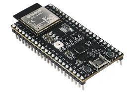
- ESP32-S2 DevKit-M1: A powerful and versatile development board based on the ESP32-S2 chip.
![]()
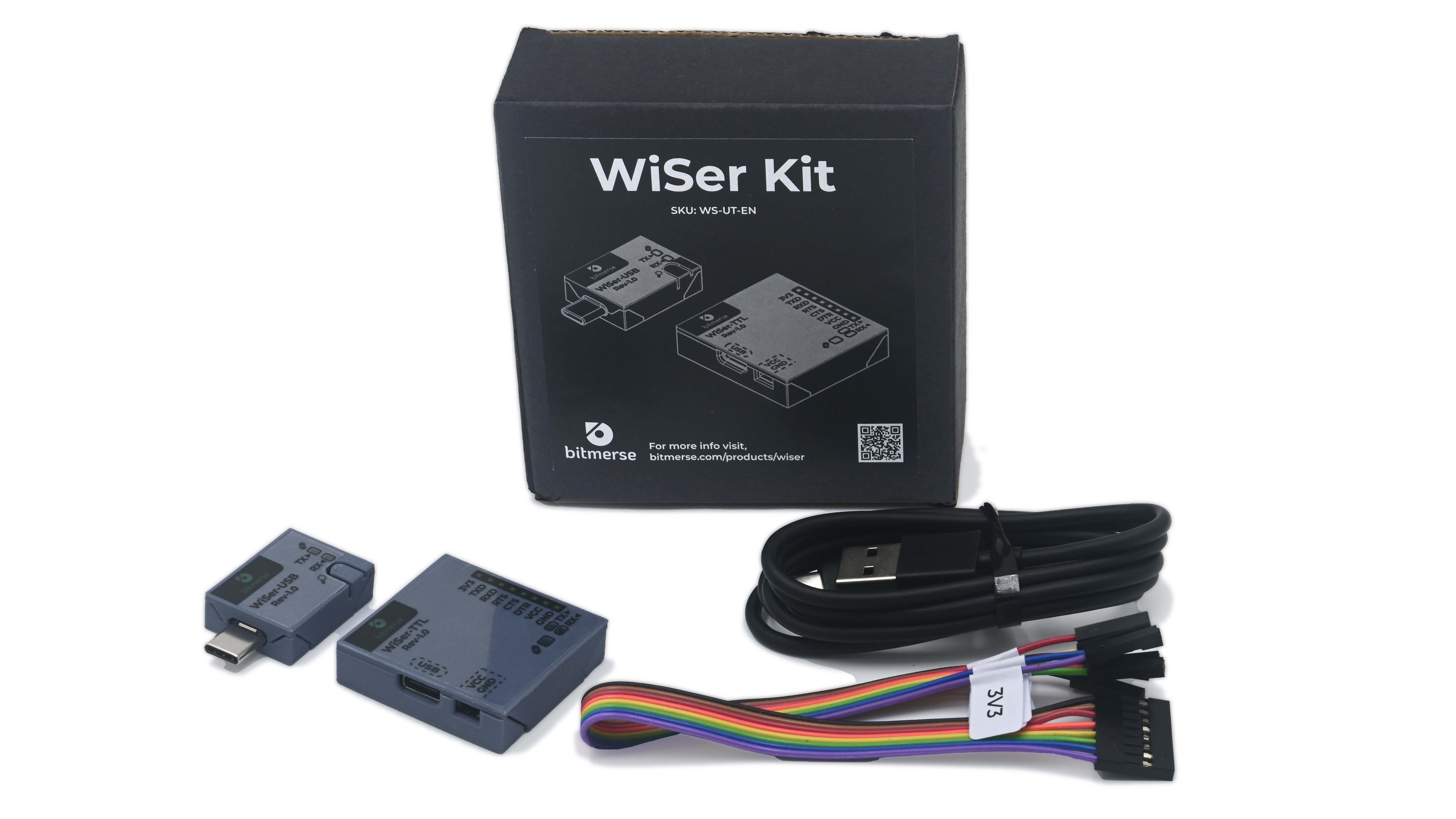
- WiSer Devices (SKU variant WS-UT-BM or WS-UT-EN): Consisting of WiSer-USB and WiSer-TTL, these wireless serial devices will serve as your programming bridge to the ESP32-S2 DevKit-M1. For more information about WiSer SKU variants, please visit WiSer Product Manual.
![]()
Prerequisites
- Get the ESP32-S2 DevKit-M1 development board.
- Ensure you have a sample example firmware for ESP32-S2 DevKit-M1. We are going use Blink example firmware in Arduino.
- Arduino IDE on Windows 10 PC or Mac with the added support of ESP32S2 Dev Module from Board Manager. Here, we are going to use Mac PC.
- Acquire a pair of WiSer devices. The WiSer-USB connects to your PC, while the WiSer-TTL interfaces with the ESP32-S2 DevKit-M1.
Step-by-Step Programming Guide
Step 1: Connect WiSer Devices
- Plug the WiSer-USB into an available USB port on your PC.
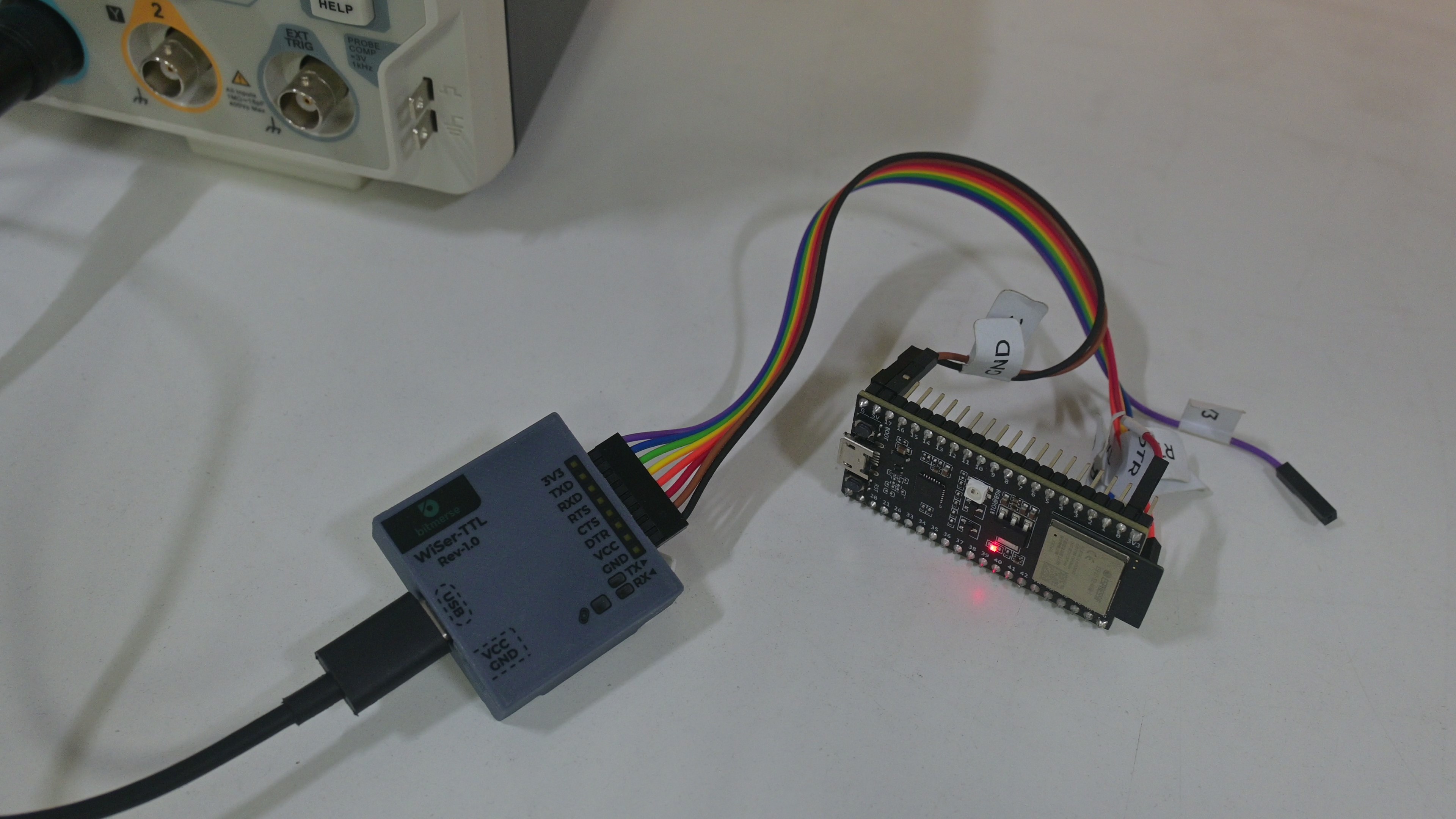
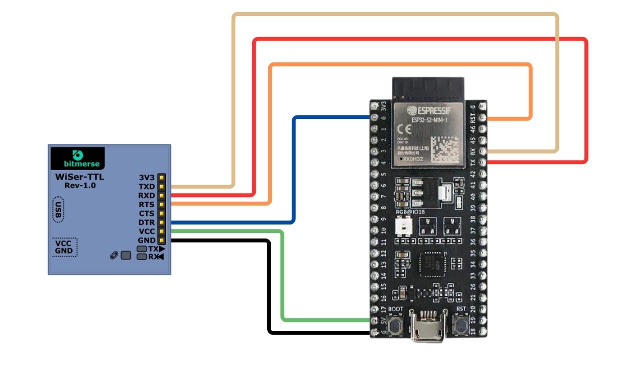
- Connect the WiSer-TTL to the ESP32-S2 DevKit-M1 as shown in the image. If you opt for an assembled WiSer-TTL variant, use jumper cables for a hassle-free connection.
![]()
Step 2: Power Up the Devices
- Power up the ESP32-S2 DevKit-M1 using a suitable power source.
- Ensure the WiSer devices are powered on. We are providing power to WiSer-TTL device through Type-C USB connector.
- In this case, we are providing power to the ESP32-S2 Devkit-M1 from WiSer-TTL by connecting VCC line of WiSer-TTL to 5V input line of the dev kit.
![]()
Step 3: Identify Paired WiSer Devices
- If you don't have multiple WiSer devices or you already know the paired WiSer-TTL device, then you can skip this step. To ensure our WiSer-USB and WiSer-TTL devices are paired with each other, short press the 'Find Pair' button on the WiSer-USB. The CONN LEDs on both paired devices will illuminate steadily for 5 seconds.
- This step helps you confirm the pairing between WiSer-USB and WiSer-TTL, especially useful when managing multiple WiSer pairs.
Step 4: Put ESP32-S2 DevKit-M1 into Bootloader Mode
Arduino IDE uses the RTS and DTR to reset and hold GPIO0 in order to put the esp32S2 Dev Board into bootloader mode.
- Verify the connection of required lines to program the board as shown in the table below.
![]()
WiSer-TTL ESP32S2 DevKit-M1 RXD TX (J3 - Pin 6) TXD RX (J3 - Pin 5) RTS RST (J3 - Pin 2) DTR 0 (J1 - Pin 2) GND G (J1 - Pin 21) VCC 5V (J1 - Pin 20) - Ensure the RTS/CTS hardware flow control is disabled on WiSer devices. To do so, long press the 'Find Pair' button on the WiSer-USB for more than 2 seconds. The CONN LEDs will flash slowly, indicating that RTS/CTS hardware flow control is disabled. For more information about 'Find Pair' button go through the overview of WiSer devices.
Note: In the case of other MCUs that are not using RTS and DTR lines to switch into the Bootloader mode, you don't need to connect these lines. Please refer specific MCU's manual for serial interface connections.
Step 5: Flashing Firmware
- With the ESP32-S2 DevKit-M1 powered on, use your preferred firmware flashing tool (such as esptool command line, PlatformIO, or Arduino) to upload the firmware wirelessly. We are using Arduino IDE here.
- The WiSer devices act as a bridge, facilitating the seamless transfer of firmware from your PC to the ESP32-S2 DevKit-M1.
Step 6: Complete the Process
- Once the firmware is successfully uploaded, Arduino IDE will reset the board in Application mode using RTS line.
- Verify that the user LED is blinking on the ESP32-S2 DevKit-M1 board.
![]()
Congratulations! You've just programmed the ESP32-S2 DevKit-M1 using the WiSer devices. This wireless approach opens up new possibilities for debugging, testing, and deploying your ESP32 projects. We can even program or update the firmware of any embedded product board which allows programming/updating the firmware over the serial interface.
- ESP32-S2 DevKit-M1: A powerful and versatile development board based on the ESP32-S2 chip.
-
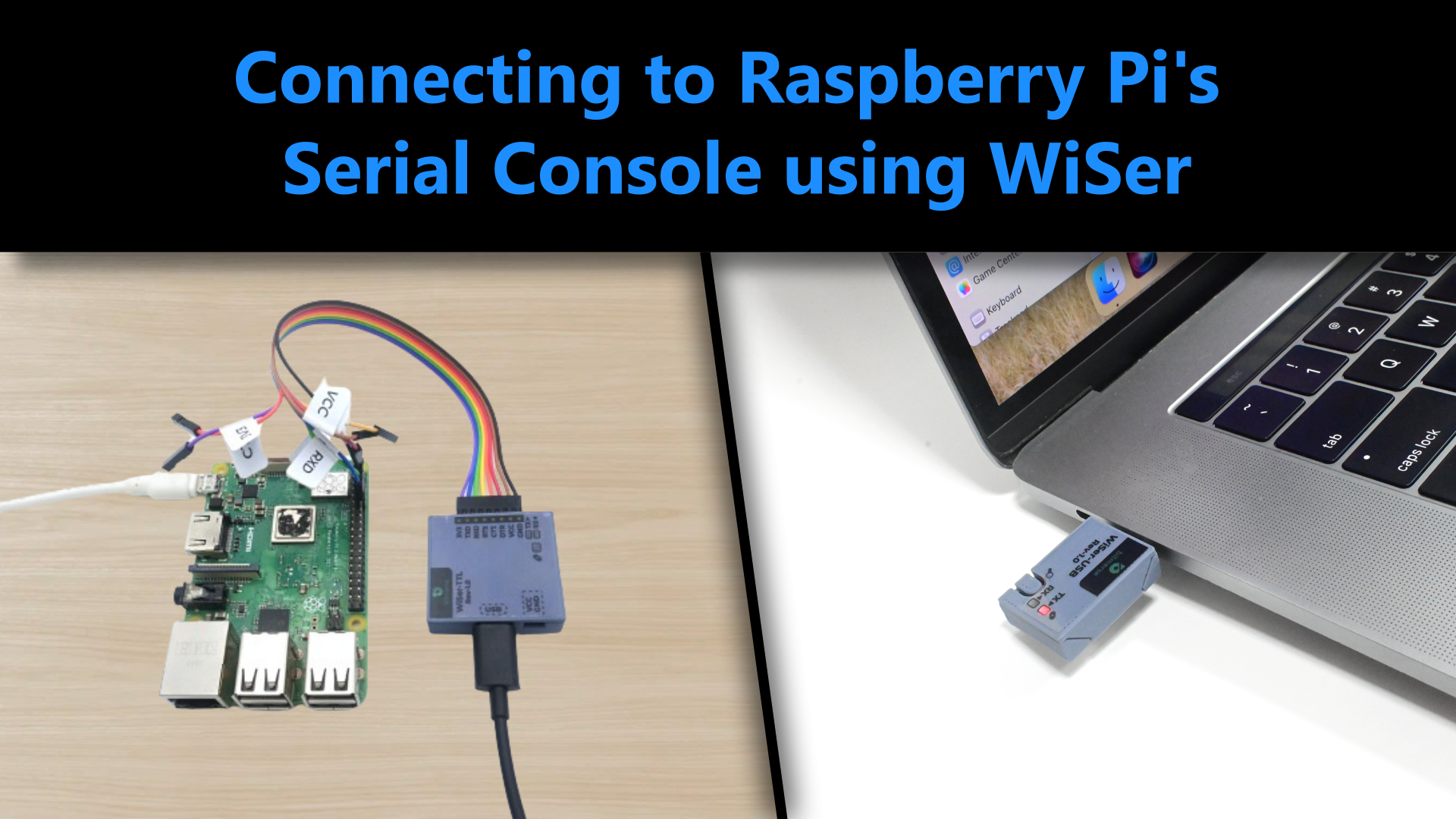
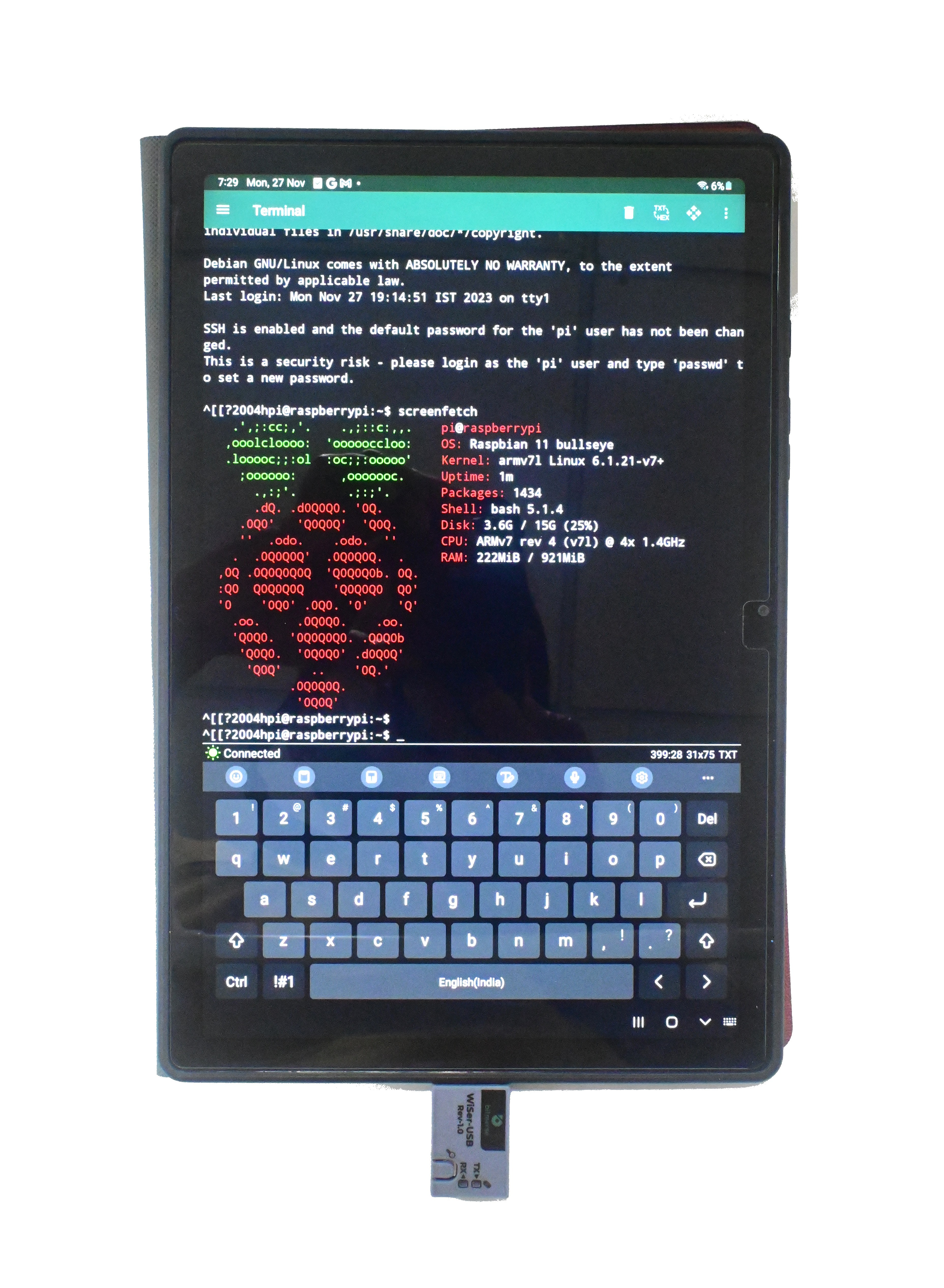
Connecting to Raspberry Pi's Serial Console using WiSer
12/09/2023 at 12:11 • 0 comments![]()
While numerous development boards exist in the market, the Raspberry Pi stands as the go-to device for hobbyists and tinkerers. And why not? It's remarkably straightforward to connect a Raspberry Pi to an HDMI display, attach a keyboard and mouse, and voilà! You have a functional setup. When lacking a display, keyboard, and mouse, you can still remotely access the Raspberry Pi via SSH by connecting it over Ethernet or Wi-Fi. But what if you lack both Ethernet and Wi-Fi connections, rendering SSH inaccessible?
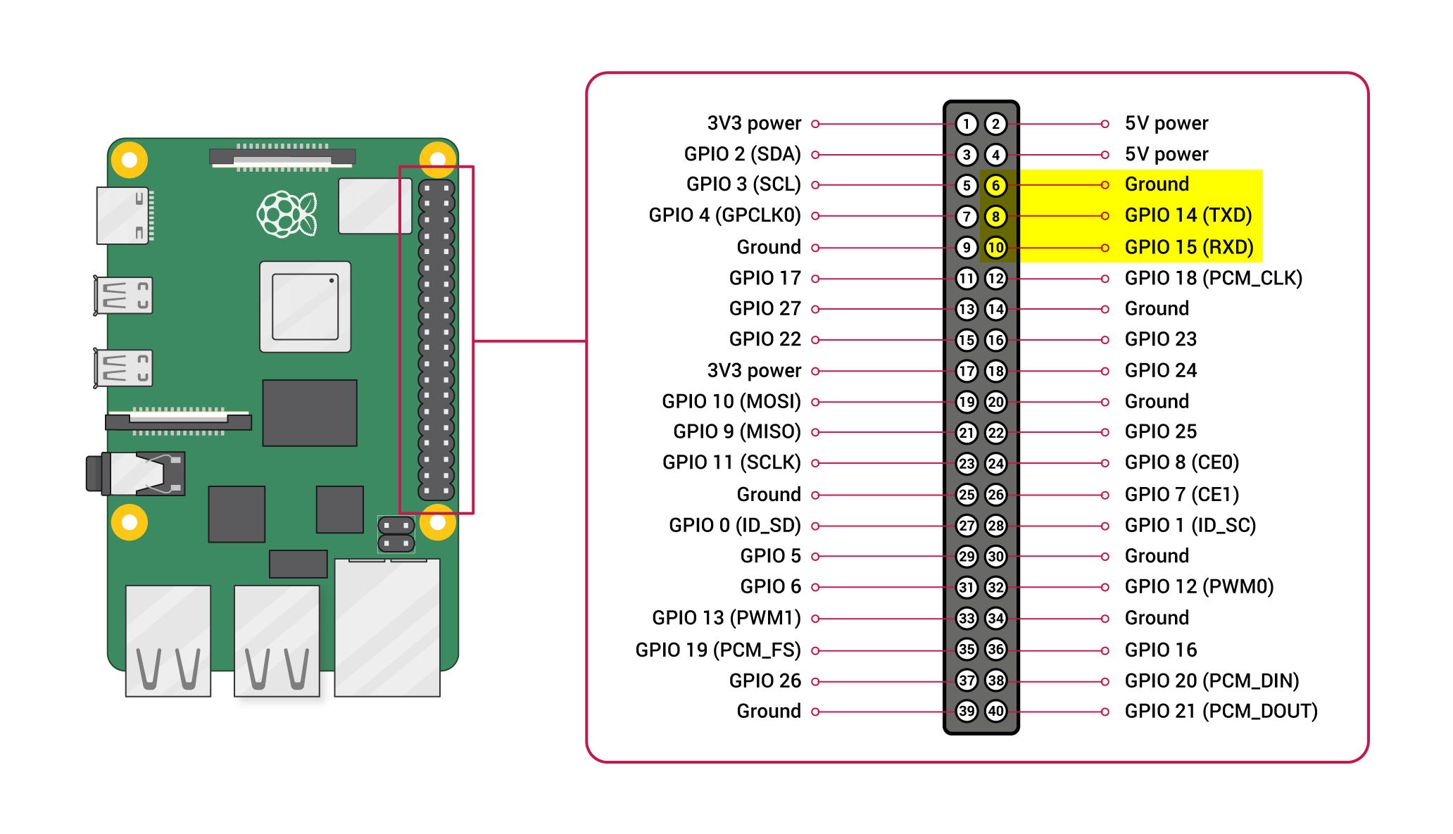
Fear not, for there is an alternative method to access the Raspberry Pi — the Serial Console. Utilizing the serial console also offers a way for users to view boot logs, providing insight into the boot-up process should users wish to tweak it. The serial console of the Raspberry Pi is accessible on the GPIO header, as depicted in the image below.
![]()
SETUP REQUIREMENTS
- PC running Windows 10 (or later)
- Raspberry Pi 3B+ (or later)
- WiSer WS-UT-EN or WS-UT-BM SKU variant (For more info about SKU variants, please refer this link)
STEPS
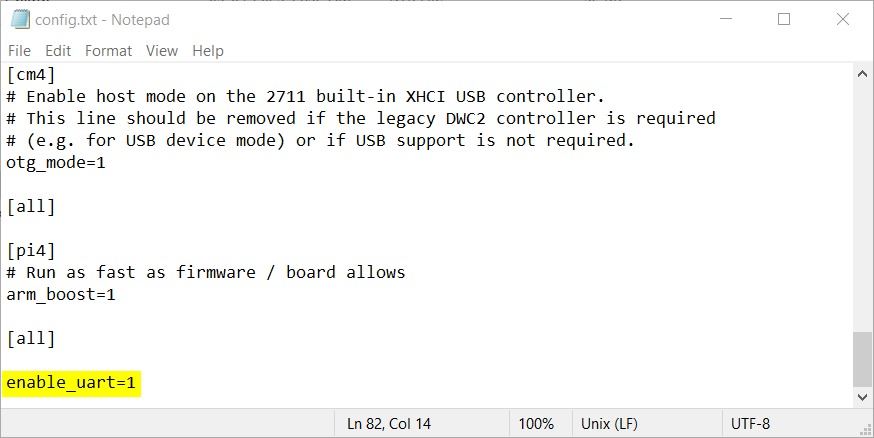
- On the Raspberry Pi, the serial port is not enabled by default. Thus, a few configuration files need editing. Insert the SD card of the Raspberry Pi into the SD card reader and connect it to the PC. Locate the config.txt file within the boot partition and add enable_uart=1 at the end of the file, as illustrated in the image below.
![]()
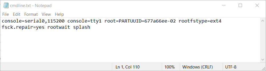
- By default, boot logs are suppressed due to settings in the cmdline.txt file within the boot partition. To view boot logs, remove quiet and plymouth.ignore-serial-consoles from the cmdline.txt file. It should resemble the example shown in the image below.
![]()
- The next step involves connecting the WiSer-TTL device to Raspberry Pi's UART pins, as outlined in the table below.
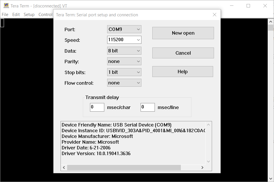
WiSer-TTL Raspberry Pi GND Ground (Pin 6) RXD TXD (Pin 8) TXD RXD (Pin 10) - To access the Serial Console, you'll need TeraTerm or a similar serial port tool. Connect the WiSer-USB device to the PC and open TeraTerm. Navigate to Setup->Serial port..., select the port corresponding to your PC's COM port name, set the speed to 115200, and click on the New Open button.
![]()
- Power up the Raspberry Pi, and the boot logs should now appear in TeraTerm.
![]()
- Having successfully accessed the Serial Console on a Windows PC using TeraTerm, for Linux distributions, GTKTerm could be employed, while Mac users may opt for SerialTools. Android phones/tablets can utilize UsbTerminal app to access the Serial Console, as depicted in the image below.
![]()
-
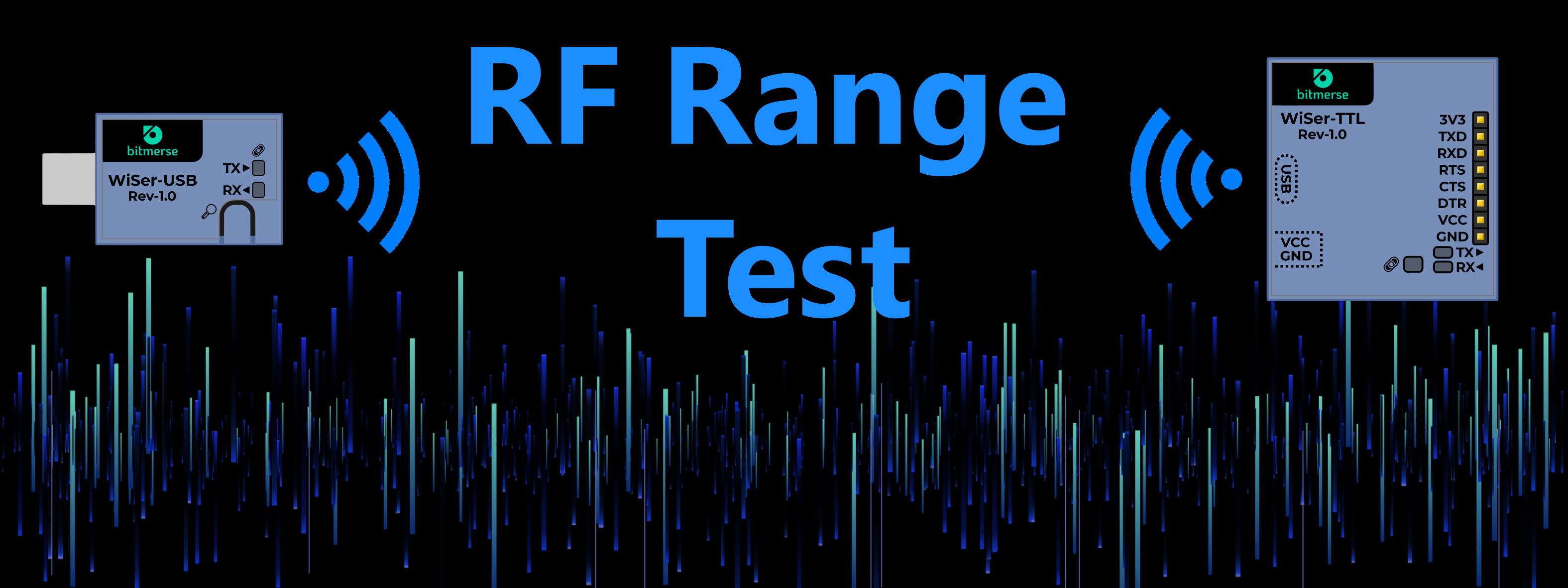
Real World RF Range Testing
11/29/2023 at 15:49 • 0 commentsWe have been testing WiSer in various scenarios. One such important test is the actual RF range of WiSer devices. The purpose of the test was to determine the physical distance from which WiSer devices can reliably communicate with each other.
![]()
HOW TO TEST?
One of the most common questions that arise for any wireless device is: How far can it transmit/receive? The range of a wireless device is determined by various factors such as transmit power, receive sensitivity, supply voltage, ambient environment, etc.
While factors like transmit power or sensitivity can be controlled by the user, the ambient environment cannot often be controlled by the user, thus playing a crucial role in defining the actual range. Recognizing this, RF testing can be conducted in both indoor and outdoor environments. Although the device will likely be used indoors, each indoor environment differs. Factors such as building structure, construction materials, room size, floors, pathways, and even furniture vary. Testing a wireless device in one indoor environment and providing an RF range may not be replicable in another indoor setting. Due to these limitations, testing the RF range of the wireless device in an indoor setup becomes meaningless.
The most effective way to determine the RF range is to test the wireless device in an outdoor, line-of-sight environment. This setup offers a means to test the RF range in optimal conditions with reproducible test conditions and similar test results.
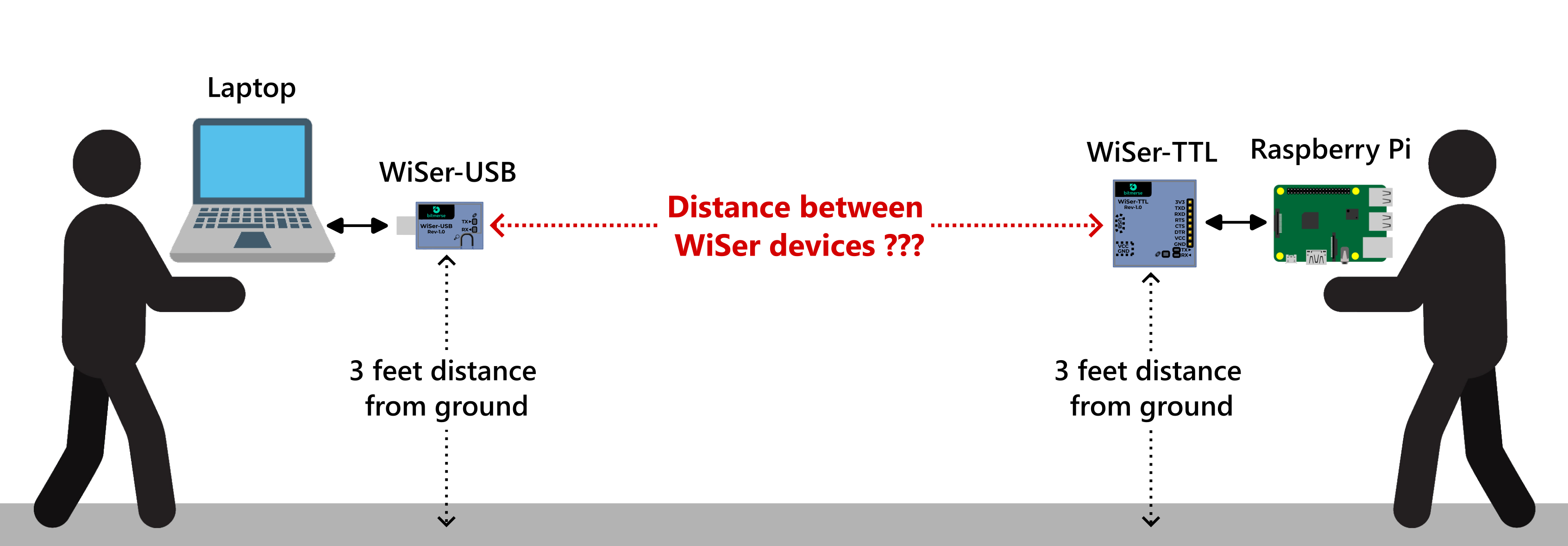
THE SETUP
![]()
The outdoor test took place in an open ground using a pair of WiSer devices, WiSer-USB and WiSer-TTL. The WiSer-USB device was connected to a laptop's USB port, while the WiSer-TTL was connected to the UART pins of a Raspberry Pi. Both devices were positioned about 3 feet above the ground with their antennas facing each other. The initial distance between the WiSer-USB and WiSer-TTL devices was set at 20 feet.
To assess data transmission between the laptop and Raspberry Pi using WiSer devices, a Python script was developed. The script opens serial port with a configuration of 921600 baud, 8 data bits, no parity, and 1 stop bit. It writes a specified size of dummy data to the serial port without delay between chunks, simultaneously reading incoming data. At the end, it prints the amount of data sent and received.
The script was executed simultaneously on both the laptop and Raspberry Pi, sending a specified data size of 1 MB. At a distance of 20 feet, we successfully received 1 MB of data on both devices. We then increased the distance between the WiSer devices and repeated the test until we no longer received 1 MB of data on either side.
FINAL RESULT
The maximum RF range we achieved was 65 feet. Thus, with a line-of-sight distance of 65 feet between WiSer devices in an open ground, the setup remained operational at the maximum supported baud rate of 921600 baud. Of course, it is possible to increase the RF range further by adjusting test conditions, such as lowering the baud rate or sending data at a slower speed by adding delays between data chunks or even allowing 5% data loss, for example. However, for this test, we specifically wanted to measure the RF range at the maximum baud rate possible, ensuring functionality with zero data loss under optimal conditions.
-
WiSer: Wireless Serial Port Connectivity
11/21/2023 at 11:58 • 0 commentsBACKGROUND
While physical serial ports are becoming increasingly rare on modern PCs, the serial port has persisted thanks to virtual serial port adaptors like FT232 or CP2102-based USB to UART converters. These converters play crucial roles in embedded systems, handling tasks such as data logging, code debugging, and firmware uploading to MCUs.
In a recent project, we employed a 6 DOF robotic arm for pick-and-place movements. To perform sensing and control, we placed an MCU at the top end of the robotic arm. During the firmware development phase, monitoring the serial logs from the MCU for debugging became essential. Initially, we experimented with a CP2102-based USB to TTL converter connected to the MCU and host system through a USB cable. However, we faced an issue where the USB cable connected to the host system obstructed certain movements of the robotic arm. To overcome this obstacle, we considered implementing a wireless serial connection between the MCU and the host system.
At first, we searched for available solutions in the market. There are certain Wi-Fi to Serial modules available, like this one. However, most of them serve as a bridge between Wi-Fi and the serial port. This means the user needs to connect to module via TCP from the host system or use com0com or similar tools on the host system to translate TCP data to Serial and vice versa. While, for some use cases, this might be perfectly acceptable, there isn't any ready-to-use hardware solution available to address this issue.
This realization led us to explore the concept of creating a wireless-to-serial bridge hardware. This gave birth to the WiSer project, an acronym for Wireless Serial. Our initial goal was to meet data logging needs, but we soon recognized its potential in remote control and monitoring, remote firmware upgrades, debugging, etc.
THOUGHT PROCESS
Initially, we considered designing a wireless device that could be connected to the embedded target device using physical serial pins. For the host system, our plan was to develop a device driver that would connect to this wireless device using the host system's Wi-Fi adaptor. The device driver would be responsible for creating a virtual serial port on the host system and transmitting/receiving data between the virtual serial port and the wireless device using the Wi-Fi protocol. Although this was a good idea, we had concerns about the process of certifying the device driver for various operating systems and potential installation/compatibility issues. Additionally, this approach was making it mandatory for users to have a Wi-Fi adaptor on the host system.
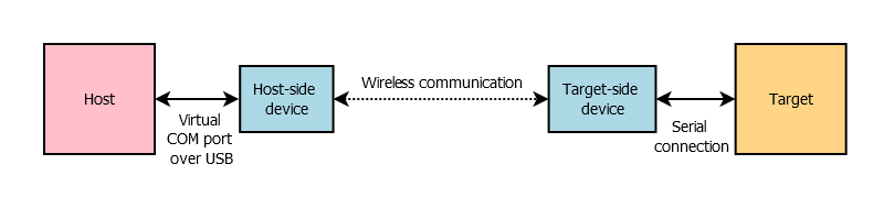
We decided to skip this idea and opted for a two-device solution, as illustrated in the image below.
![]()
This approach eliminates the main problem of requiring a custom device driver on the host system. Since most modern operating systems already have a built-in virtual serial port driver, we decided to leverage that advantage. So, the host-side device will act as a USB device with CDC class support. The target-side device will have serial pin connections (TX, RX, RTS, CTS, etc.) tied to to target's serial pins. Both of these devices will communicate wirelessly to exchange data.
For wireless communication, we explored a few options like BLE, Wi-Fi, and Sub-GHz. Although Sub-GHz can provide a longer coverage range compared to BLE or Wi-Fi, as the operating frequency for Sub-GHz varies based on country/region, we ruled out that option. Wanting to support the maximum data speed with these devices prompted us to choose Wi-Fi, as it can provide a higher data throughput rate compared to BLE.
For Wi-Fi, there are ready-to-use Wi-Fi modules available that can be soldered onto the PCB, but we wanted to make the devices as compact as possible, and a Wi-Fi module may hinder this requirement. So, we decided to use Wi-Fi SoC directly instead of a Wi-Fi module/SoM.
The next step was to select a Wi-Fi SoC for both devices. We went through Wi-Fi offerings from Espressif Systems, TI, and Infineon/Cypress, but in the end, we finalized the ESP32-S2 from Espressif Systems as it meets all technical requirements while remaining cost-effective.
The next decision was how data needs to be exchanged between these two devices. Initially, we thought to create a Wi-Fi access point on one device, and the second device would work in Wi-Fi station mode. The second device should automatically connect every time it's powered on. We would then also need to hide the SSID and add other security mechanisms to prevent users from connecting to this Wi-Fi access point. On top of it, we would also need to use TCP or a similar protocol to exchange the data. Going through the details of the ESP32-S2 MCU, we found out that Espressif provides a wireless communication protocol called ESP-NOW. While we definitely could implement data exchange through TCP over Wi-Fi, we found ESP-NOW to be more suitable as it offers a direct and straightforward method for establishing peer-to-peer communication. This protocol can coexist with nearby Wi-Fi and BLE devices operating on 2.4 GHz. So, we finalized on using the ESP-NOW protocol between the two devices.
DETAILS
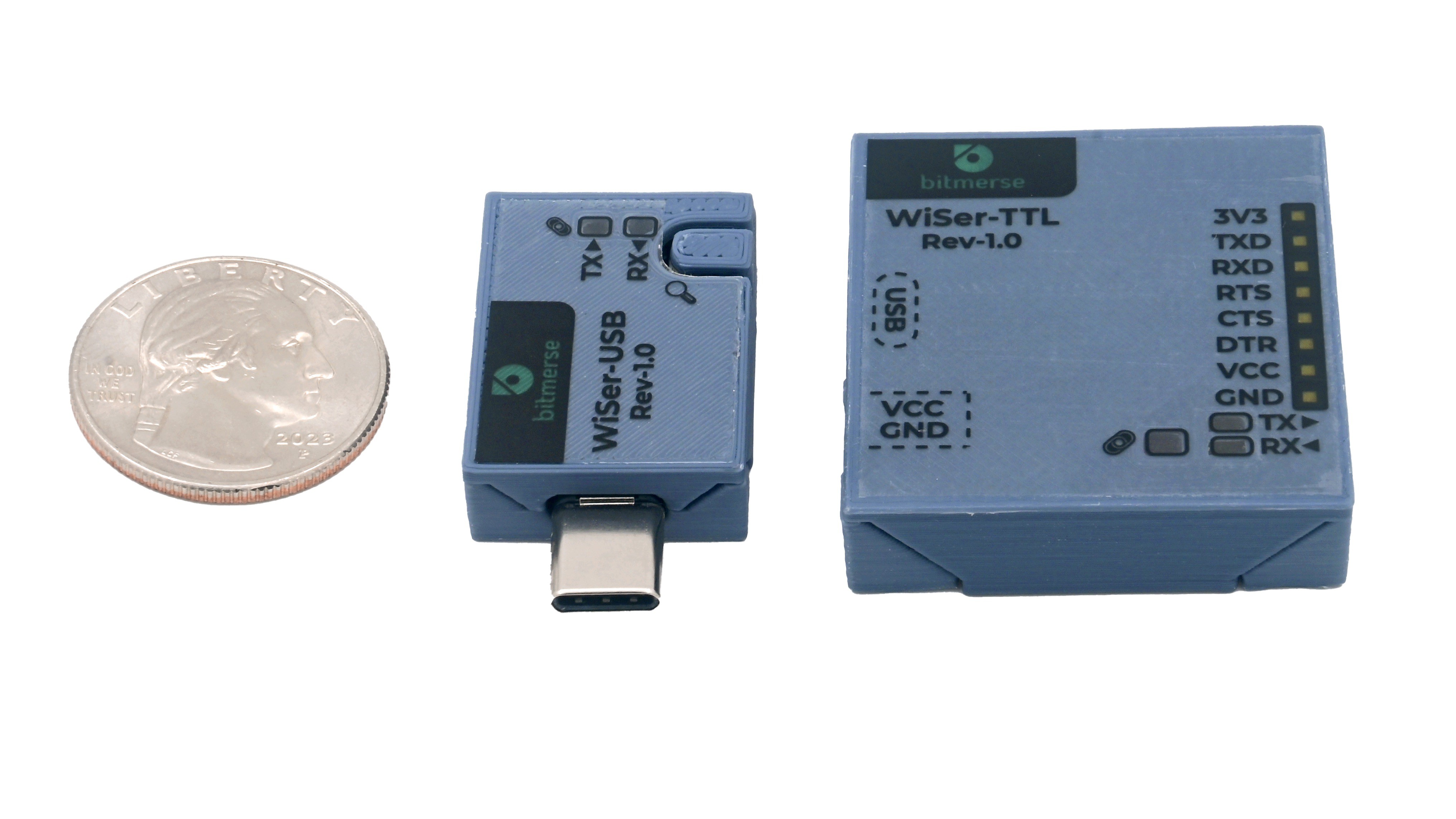
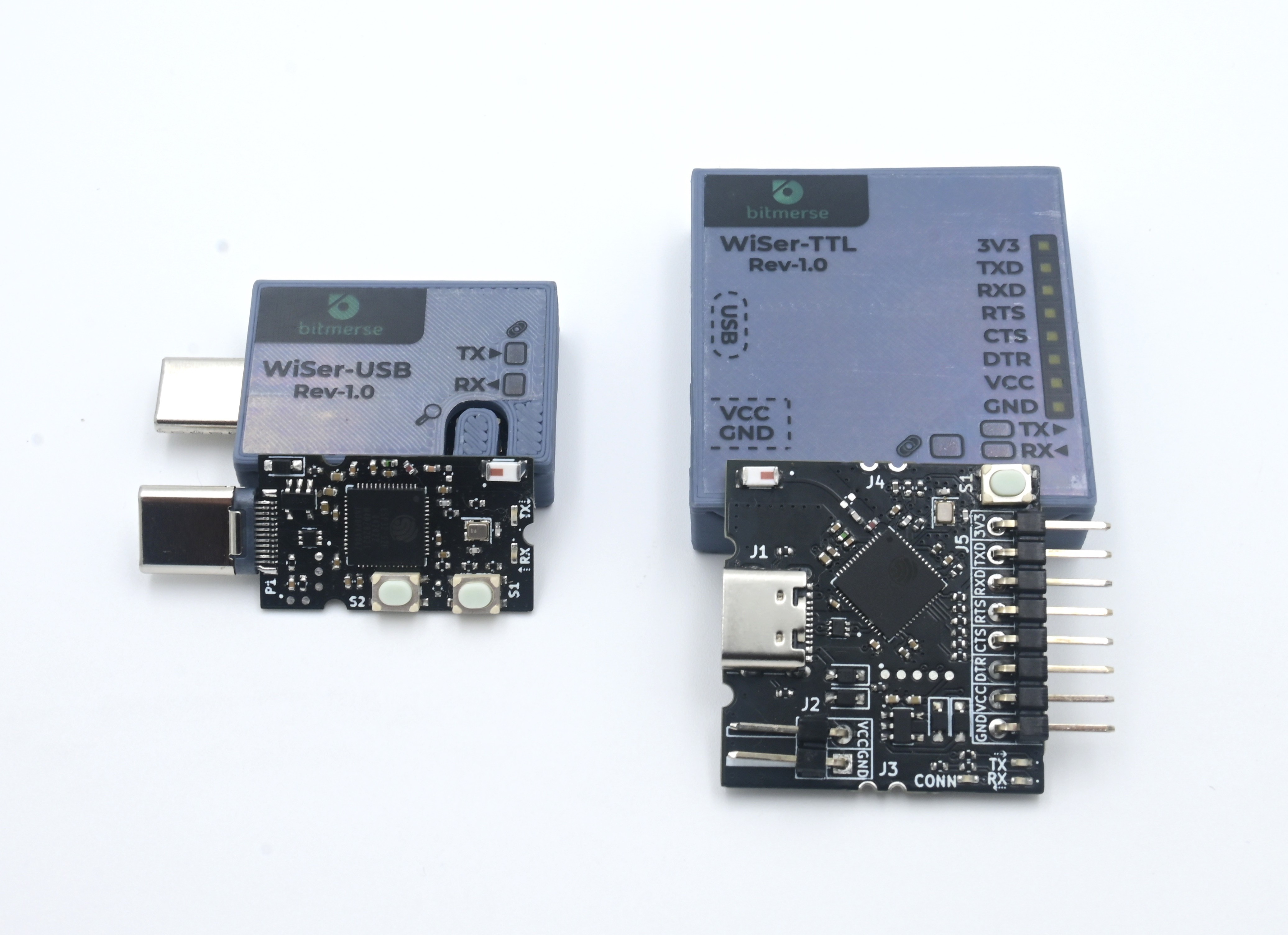
With several weeks of hard work, we were able to produce these two little devices:
![]()
![]()
For setup, the user needs to insert the WiSer-USB device into the host system, connect the WiSer-TTL device to the target device, and that's it! No additional driver or software installation is required. The WiSer-USB device functions as a virtual serial port on the host system and establishes a peer-to-peer wireless connection with the paired WiSer-TTL device. The WiSer-USB device is compatible with any serial port software, such as PuTTY, Tera Term, or any other software that supports serial port communication. Users can instantly access the serial port on the host system and perform various tasks using WiSer, just like they do with a typical USB-to-serial converter.
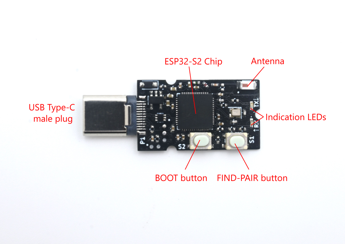
WiSer-USB
![]()
The WiSer-USB functions as the host-side device and is equipped with the ESP32-S2 chip for data processing and wireless communication.
A BOOT button is provided to put the device into boot mode for firmware upgrades.
LEDs are incorporated to indicate TX and RX activities.
The FIND PAIR button facilitates the search of paired WiSer-TTL device, particularly useful when multiple WiSer devices are in use. It helps users identify WiSer device pairs through LED indications.
The WiSer-USB device is powered through a USB Type-C male plug when connected to the host system. The decision to use Type-C instead of Type-A was made to align with the increasing use of USB Type-C female connectors in modern computers/devices. Additionally, having a Type-C male plug enables compatibility with phones or tablets.
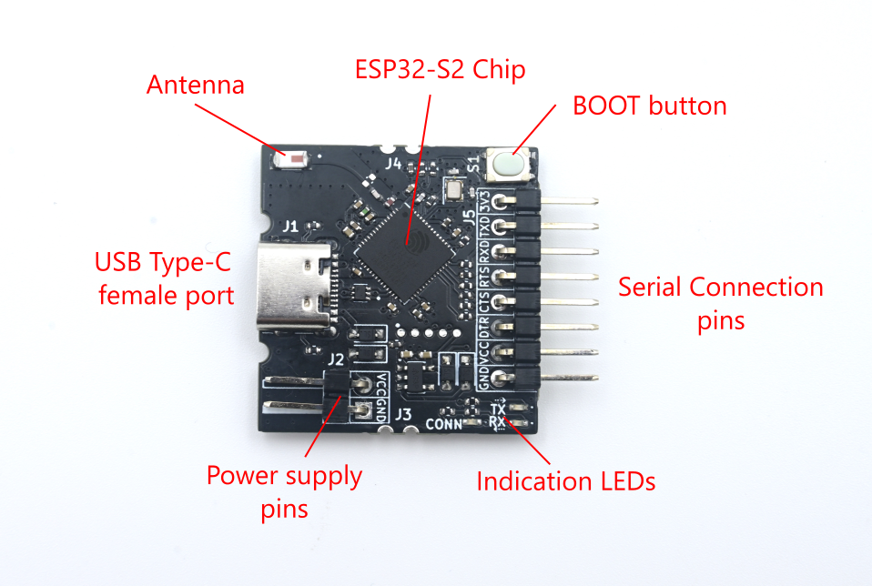
WiSer-TTL
![]()
The WiSer-TTL functions as the target-side device and is also equipped with the ESP32-S2 chip for processing and wireless communication.
Similarly, a BOOT button is provided to put the device into boot mode for firmware upgrades.
LEDs are incorporated to indicate TX, RX, and CONN activities.
The WiSer-TTL device can be powered in multiple ways:
- Using the USB Type-C female connector.
- Through dedicated header pins (J2).
- Via castellated pins (J3).
Power through the USB Type-C female connector can be supplied from power adapters, power banks, or the host system itself using a USB Type-C cable.
Dedicated header pins are also provided to allow power supply through jumper cables.
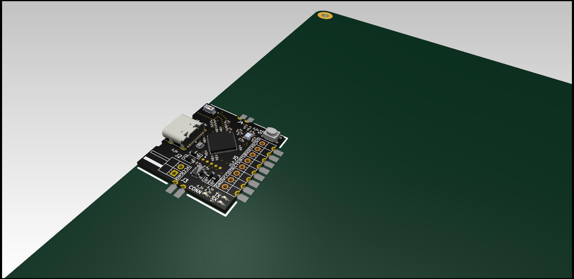
The WiSer-TTL device can also be mounted directly to a PCB, and power supply and serial connection pins can be directly soldered to PCB traces. The image below shows such an example:
![]()
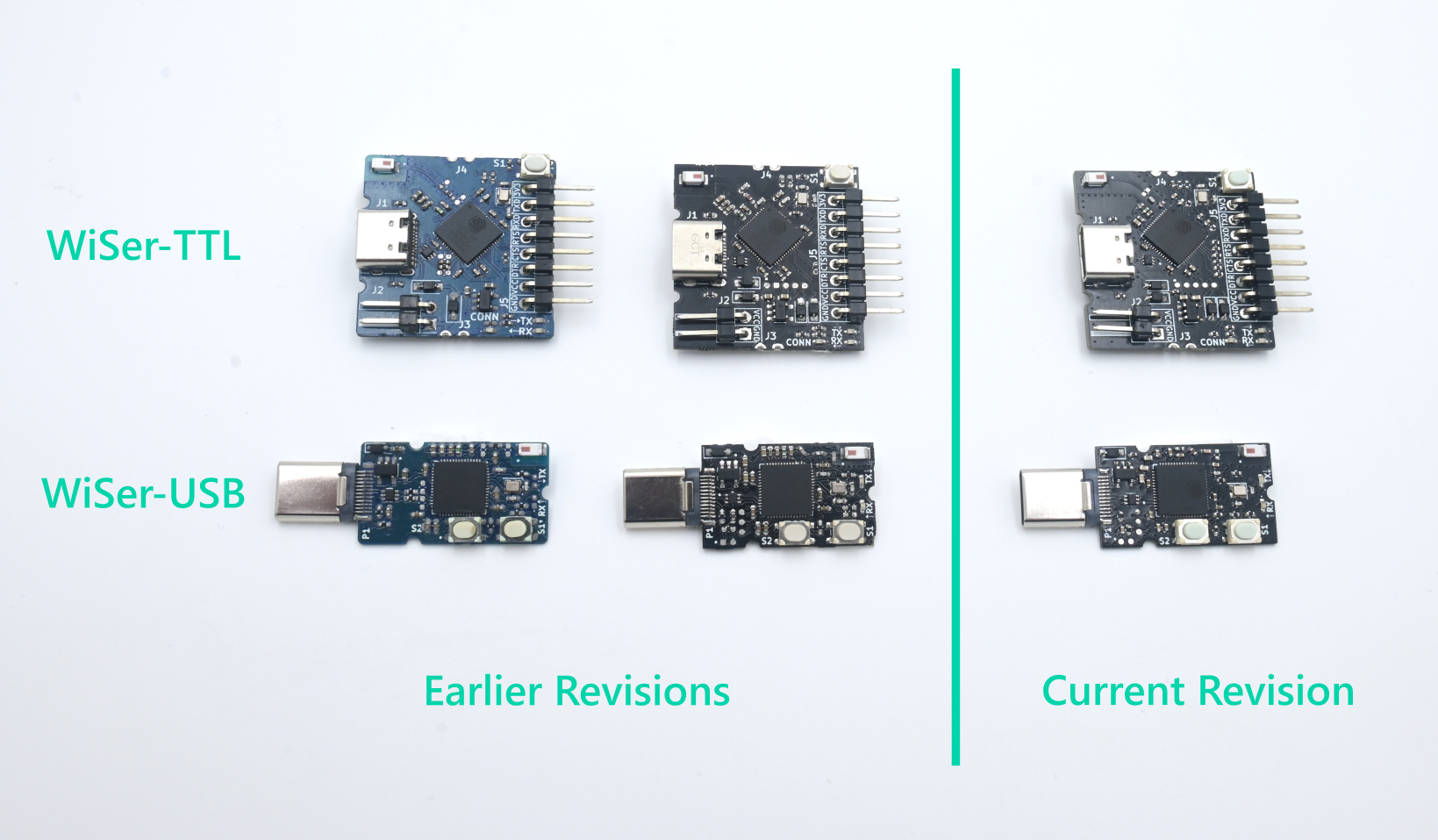
The below image shows the evolution of WiSer devices through various iterations:
![]()
CURRENT STATUS
The following table illustrates the currently supported serial port features on WiSer:
Host Platforms Windows, Linux, and Mac host systems, as well as Android phones/tablets Baud rates Any standard or custom baudrate upto to maximum 921600 baud Flow control software (XON/XOFF), hardware (RTS/CTS), and None Data bits 6-bit, 7-bit, 8-bit Parity types NONE, ODD, EVEN, MARK, and SPACE Misc. Feature Equipped with DTR control pin We attempted to test the WiSer-USB device with an iPad and the latest iPhone equipped with a Type-C female connector, but iOS does not permit it to function as a virtual serial port. Therefore, iPad and iPhone support is not available at the moment.
The WiSer devices are presently undergoing thorough testing across different scenarios. Once testing is completed, the source code and hardware design files will be released under open-source license and uploaded to this repository.
Stay tuned for more updates on WiSer!