The first stage of the project requires the building of a basic transmitter and detector. This is necessary in order to verify the correct generation of infrared signals.
Building a Basic Detector
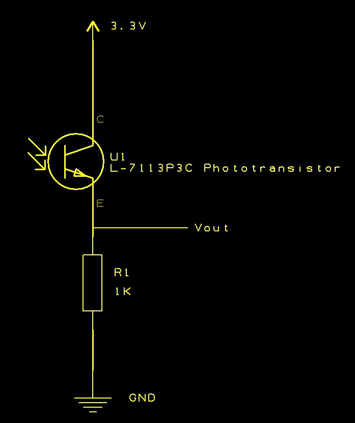
The basic detector is composed of a phototranstistor (L-7113P3C) the the collector connected to Vcc and the base connected to ground through a resistor. The phototransistor operates in much the same way as a conventional transistor except that the base is not connected electrically to the circuit. Instead, the base is made sensitive to infrared light. The detector circuit is as follows:
 Wiring up this circuit on breadboard and connecting Vout to an oscilloscope gives the following output when a random remote control from home is pointed directly at the phototransistor:
 At this point we can detect infrared signals, the next stage requires the creation of a transmitter.
Building a Basic Transmitter
Infrared LEDs work in the same way as a convention LED with two main differences that we should be aware of:
- They work in the infrared spectrum
- The current draw is much higher than a conventional LED (100mA is not uncommon)
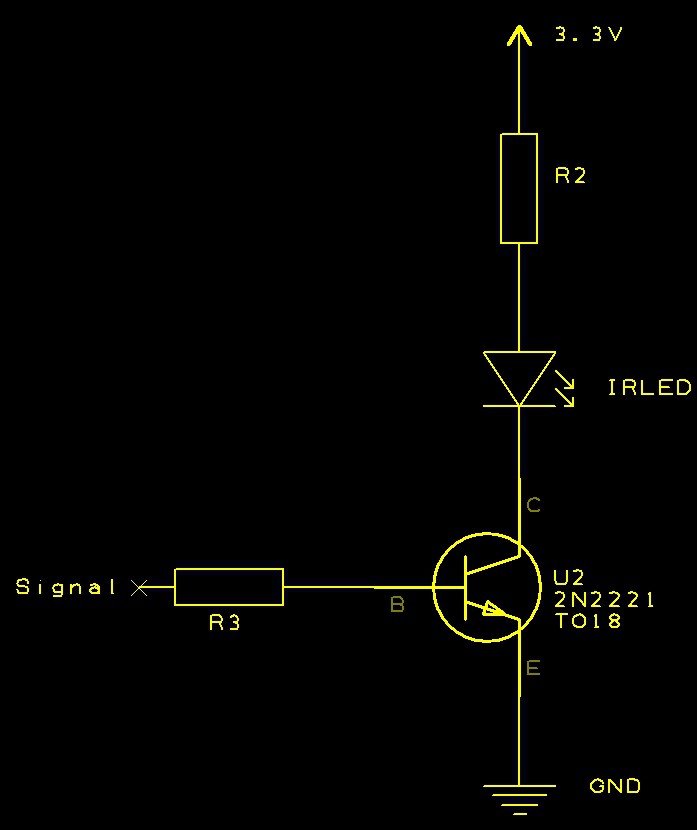
The high current draw rules out the supply of current from a microcontroller directly to the LED, instead a basic transistor circuit is required where the transistor is configured to be used as a switch when a small current is applied to the base. The schematic for this is as follows:
 For the initial experiment, select a value of R2 to allow 20mA to flow through the transistor. R3 should allow only a few milliamps to flow to the base of the transistor.
Testing
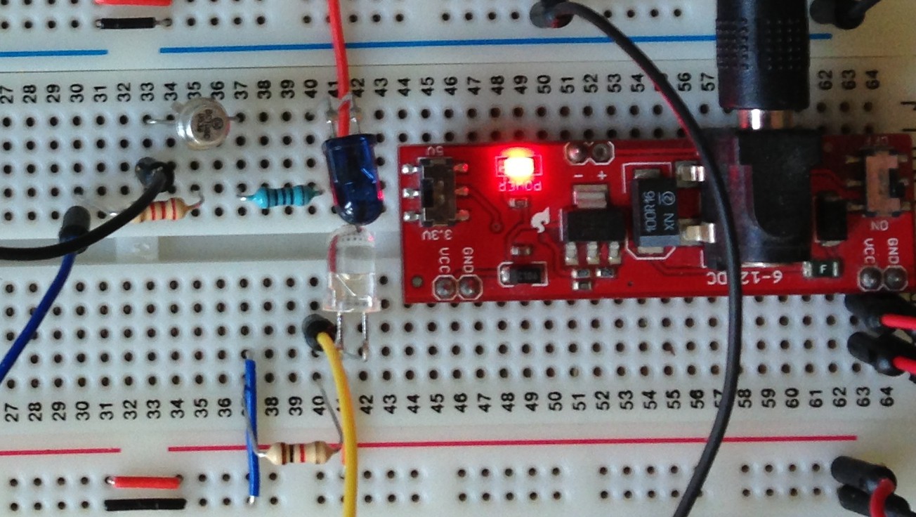
In order to test this it is necessary to build the detector and transmitter circuit on breadboard so that the infrared LED is pointing directly at the phototransistor:
 The upper side of the breadboard contains the transmitter (the blue LED is actually an infrared LED). The lower half of the breadboard contains the detector.
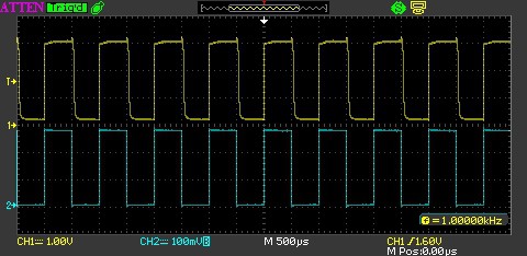
Connecting a scope to the detector and a signal generator to the transmitter should allow the verification that the circuit is functioning as expected.
 The yellow trace above shows the output from Vout in the receiver circuit. The lower blue trace shows the output of the signal generator which is connected to the base of the transistor in the transmitter circuit.
Conclusion
With a functioning transmitter and a functioning receiver the project can now progress to connect in a microcontroller to provide modulation to the transmitter output.
 Nevyn
Nevyn
Discussions
Become a Hackaday.io Member
Create an account to leave a comment. Already have an account? Log In.
STM8S 38KHZ输出2%占空比?
Are you sure? yes | no