Dirk-WIllem van Gulik
-
Generating a playlist for the LEDs
12/29/2023 at 21:55 • 0 commentsWith this we can generate a playlist for the LEDs. And with a very simple player we can play these out as text for debugging. Or shunt into the PCB as firmware.
-
Getting Light Characteristics
12/29/2023 at 21:51 • 0 commentsSo we have a working set of blinkenlights. The next challenge is translating the map sequences to the right flashing lights. And get this stuff compact enough to fit in the few 100 bytes we have in a STM8 CPU.
There are some libraries in Pascal, Javascript and Python that allegedly convert these sequences. The first attempt with python its light-character seems to output sensible code.
Running various sets of lights show that most of the generated sequences have a lowest common `shortest change time' somewhere in the 0.2 to 1 second; and that the most complex sequences are early longer than 20 steps or 50 seconds.
This means that writing these out as sequences of bits is not ideal; but that some sort of playlist would likely fit in a few bytes per steps if we accept that we need to store 2 or so values per light. With the above - these appears to still fit in 8bits. So that is doable for the 30-50 lights typically expected.
-
Testing the LEDs
12/29/2023 at 21:38 • 0 comments -
Day 16 - Bringup
12/29/2023 at 21:31 • 0 commentsNext up is bringing up the board.
This was done in several steps; first one board was readied with just the CPU, power conditioning, the power LED and the 'ACT" debugging LED. But without the LED driver or any of the LEDs.
For this a simple programme was written:
The full code can be found on GitHub.// Test LED "2" -- R124 needs to be in place or jumpered // #define LED_PORT PC #define LED_PIN PIN4 int main(void) { /* Set clock to full speed (16 Mhz) */ CLK_CKDIVR = 0; /* GPIO setup */ // Set pin data direction as output PORT(LED_PORT, DDR) |= LED_PIN; // i.e. PB_DDR |= (1 << 5); // Set pin as "Push-pull" PORT(LED_PORT, CR1) |= LED_PIN; // i.e. PB_CR1 |= (1 << 5); while(1) { // LED on PORT(LED_PORT, ODR) |= LED_PIN; // PB_ODR |= (1 << 5); delay(100000L); // LED off PORT(LED_PORT, ODR) &= ~LED_PIN; // PB_ODR &= ~(1 << 5); delay(300000L); } } -
Day 14 - soldering
12/29/2023 at 21:22 • 0 commentsNext up was a bit of experimentation as how to solder this; without ruining colour. Using a relatively hot SMD oven caused a slight browning of the imagery. The same was found when using a hot air gun indiscriminately.
Normal traditional soldering; or gentle hot-air in limited areas worked well - with no discolouring discernible. The one exception was near the USB-C connector. One needs to really heat this up to get the solder to flow well enough for a good mechanical fix (future versions probably should simply use two power pins; rather than USB to prevent this).
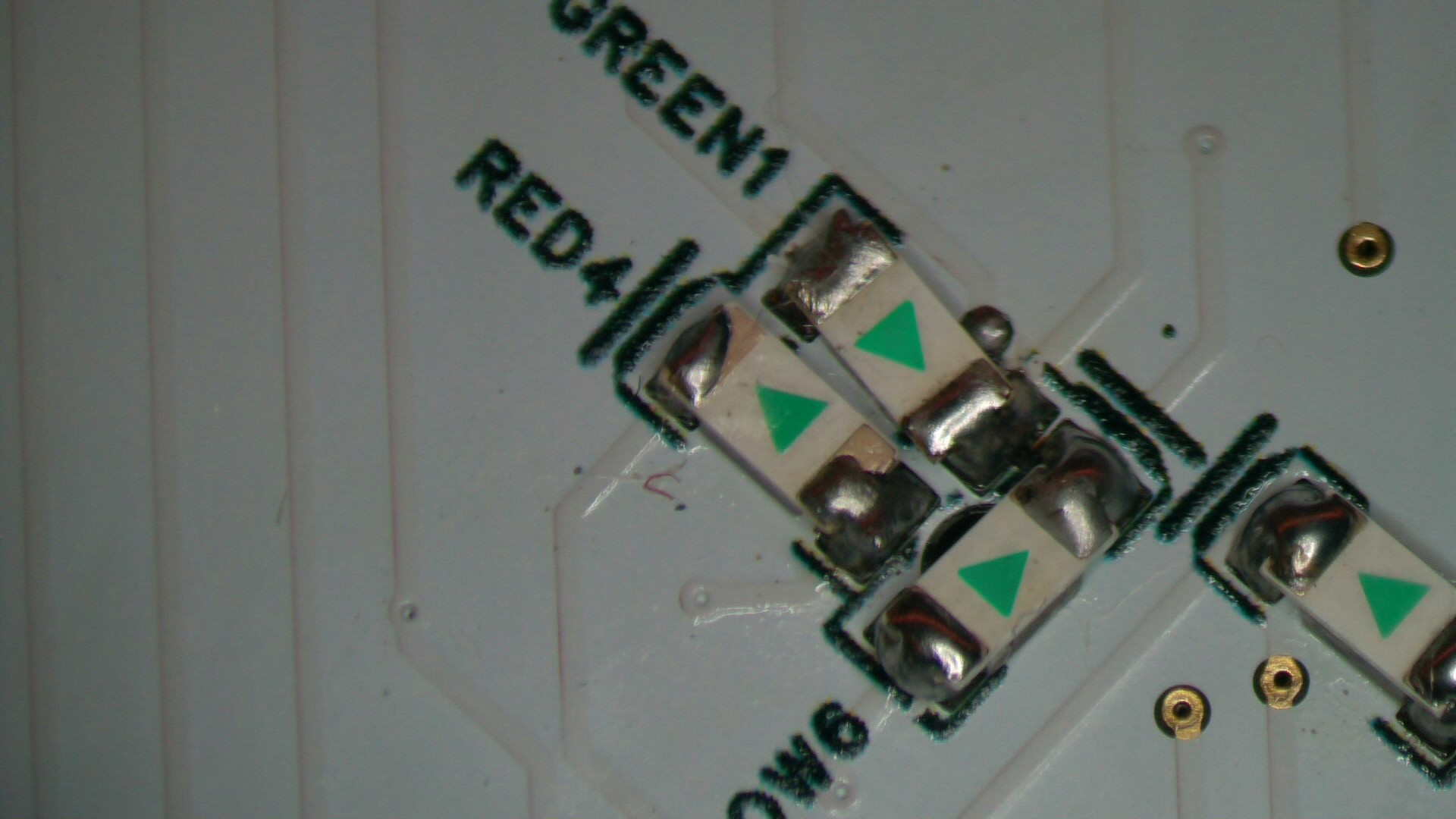
The reverse LED soldering was slightly more challenging. As we wanted them to be `on top' of the PCB - rather than `fall' through a square hole.
![]()
Turned out this was best done by putting a small blob of solder on one side; hold the LED against it; solder that one side; then let solder flow under the older side. And then complete the first side.
-
Day 12
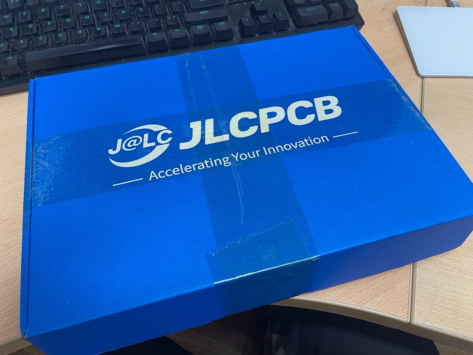
12/29/2023 at 21:14 • 0 commentsAbout 12 days later (most of this was taken up by shipping) - the post brought a nice looking box:
![]()
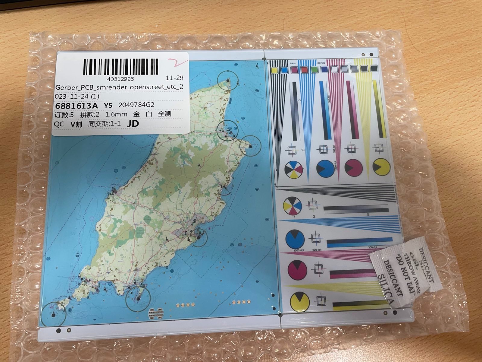
With 5 very lovely looking boards !
![]()
All nicely packaged and sealed.
-
Day 2 - design sent off
12/29/2023 at 21:13 • 0 commentsThe final design was submitted to JLCPCB.
Sailing the 7 Seas -- nautical blinkenlights
Nautically correct blinkenlights that flash just like the real lighthouses and buoys; on a colourful nautical map thanks to JLCPCBs new PCBs