-
Pi 5!
02/23/2024 at 02:12 • 0 commentsI've added a few cool upgrades and new features to the booth since my last update. One of the biggest is that I decided to upgrade from the Pi 4B to the Pi 5!
The Pi 5 offers a few key improvements:
- Faster image remapping, for lens correction (among the new features I added)
- Built in RTC to give photos accurate timestamp for EXIF data (another new feature)
- Temporal denoising of images from the camera
- Coolness
Each of these on their own isn't enough to justify the switch, but when a new Pi comes out after 5 years of waiting, you can't not put one in a project.
Here's a rundown of the new features I've added to the photo booth.
Distortion Correction
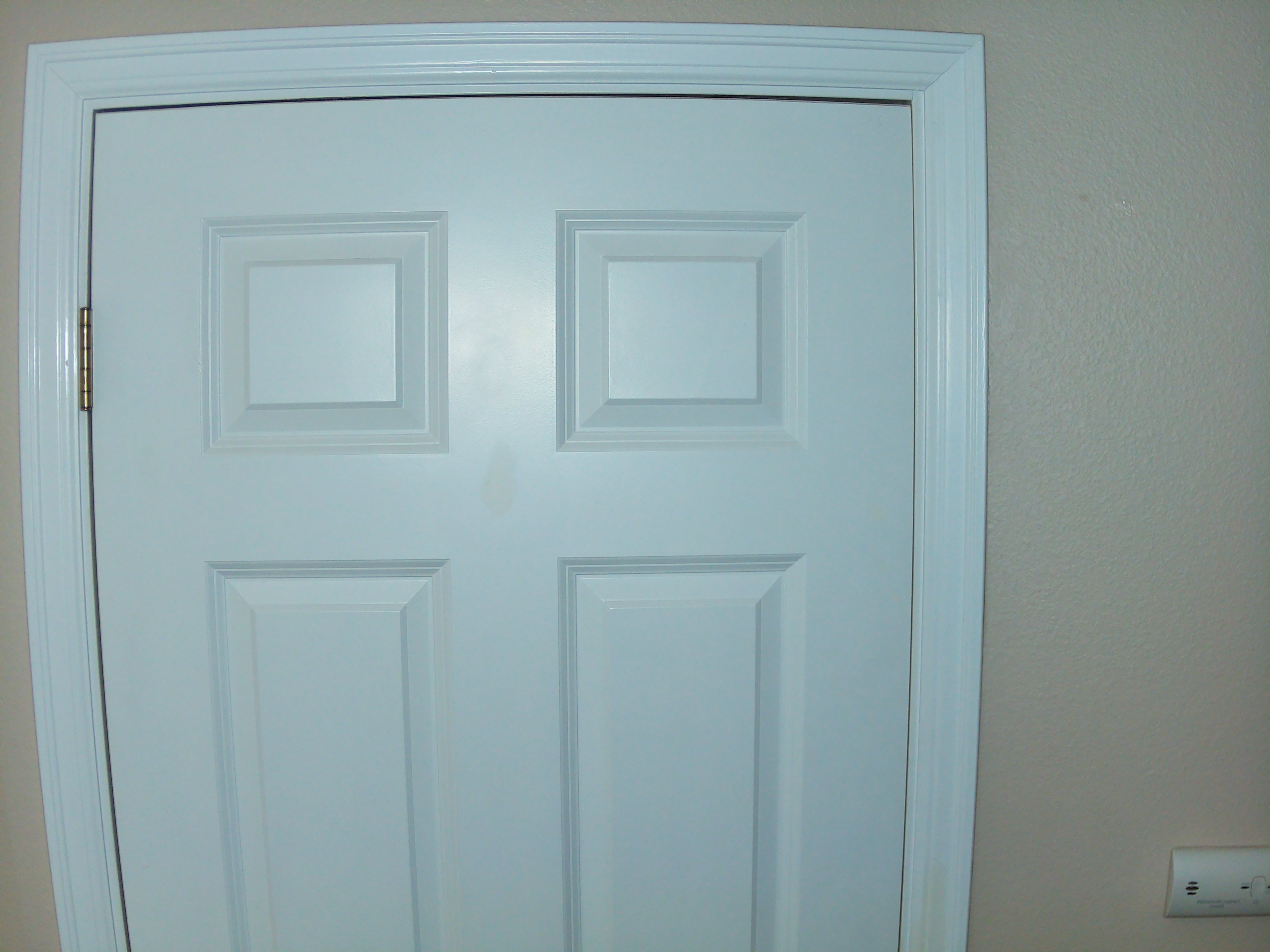
The officially sanctioned Pi HQ Camera M12 Portrait lens is the best M12 lens with an appropriate focal length that I've found so far, though I've only tested it against two AliExpress lenses that didn't quite measure up. Its main drawback is that it has a surprising amount of barrel distortion for being a portrait lens. This door photo shows how curvy it gets at the edges.
![]()
This distortion isn't super noticeable for most photos, but can make people's faces at the edge of the frame look a little weird. In my search for maximum image quality, I decided to take advantage of OpenCV's easy distortion correction functions.
Correcting for the distortion involves printing out a checkerboard, taking a bunch of pictures holding the checkerboard, running a quick script to get the lens intrinsics, and implementing the distortion correction in the main photo booth script.
![]()
Here's my quick and dirty script that reads the checkerboard and outputs a file of the lens correction (warning, magic numbers and hardcoded paths abound).
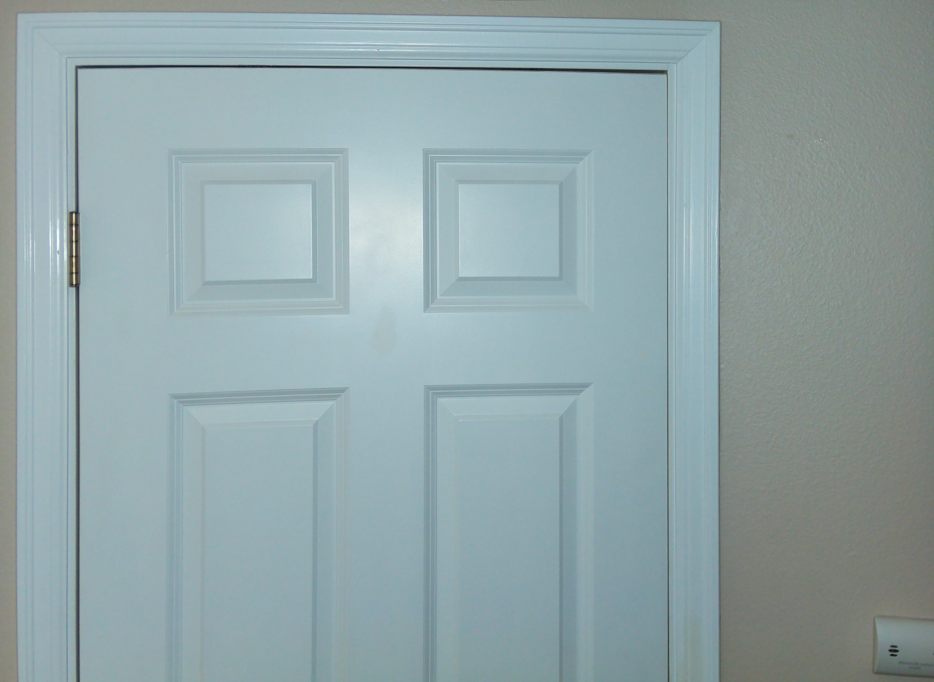
The main booth.py file looks for the the intrinsics file (set in config.yaml) and if it exists, it remaps the image. Here's the result of the remapping on the door photo above.
![]()
Glowy Pulsing LED Button
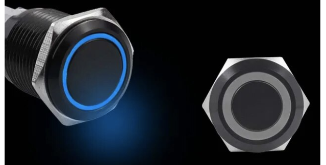
When testing the photo booth at an NYE party, I discovered that the distinction between the button and camera weren't clear to some users, despite their different locations and appearances. To help make sure that everyone would know where to put their finger, I added a nice button with a blue LED ring surround, and added code to give it a smooth pulsing effect. The best one I could find is on AliExpress, linked below. I went with the 22mm size.
![]()
Hardware PWM
The switch from the 4B to 5 necessitated a few changes to the software. The 5 doesn't support the pigpio library that I was using to control the LEDs and read the button, so I switched to gpiozero. However, I wasn't super happy with the PWM control in this library, so I switched to using the rpi_hardware_pwm library. I had to modify it a bit to get it to work with the pins I wanted, so I submitted a PR to hopefully get that fixed soon.
EXIF Data
I discovered that no matter how you name your files, when you upload them to iCloud or Google Photos, they get shuffled randomly in the resulting album. This was pretty annoying, especially when I wanted to upload both the color and monochrome photos to the same album, because the color images wouldn't show up next to their monochrome version. I realized that what they want for chronological sorting is timestamps in the EXIF metadata of the images. I used the piexif library to add the timestamps as EXIF, and voila, the photos are sorted in chronological order!
formatted_datetime = datetime.now().strftime("%Y:%m:%d %H:%M:%S") zeroth_ifd = {piexif.ImageIFD.Make: "colin", piexif.ImageIFD.XResolution: (w, 1), piexif.ImageIFD.YResolution: (h, 1), piexif.ImageIFD.Software: "colin p" } exif_ifd = {piexif.ExifIFD.DateTimeOriginal: formatted_datetime, piexif.ExifIFD.LensMake: "colin", piexif.ExifIFD.Sharpness: 65535, piexif.ExifIFD.LensSpecification: ((1, 1), (1, 1), (1, 1), (1, 1)), } exif_dict = {"0th":zeroth_ifd, "Exif":exif_ifd} exif_bytes = piexif.dump(exif_dict) img.save(image_path, quality=95, exif=exif_bytes) -
Mechanical Design and Construction
12/23/2023 at 04:41 • 0 commentsThe enclosure for the Photo booth consists of 4 sides made of acrylic and top and bottom caps 3D printed in ABS that hold the whole thing together. It’s not glued or screwed together, just held together by firmly pressing the sides into slots into the top and bottom caps. This makes it less robust than it could be, but it’s easy to take apart for documentation!
![]()
![]()
![]()
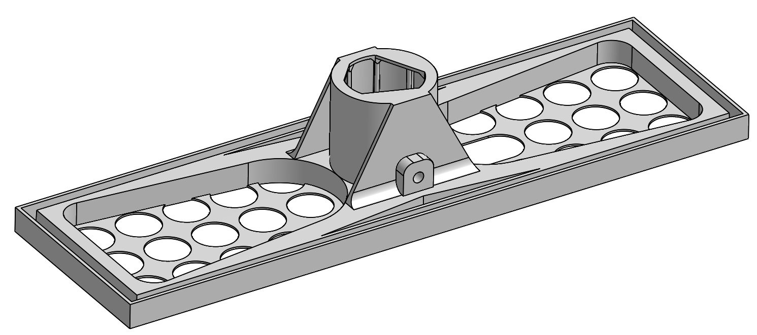
The bottom of the enclosure is a big old 3D printed piece of ABS with a hole so it can sit on the tripod, which is a surprisingly sturdy and cheap monitor stand from Monoprice. I didn’t install the monitor bracket so the photo booth just sits directly on the pole.
![]()
The bottom piece. Just barely fits on the 300x300 bed of my Voron ---------- more ----------![]()
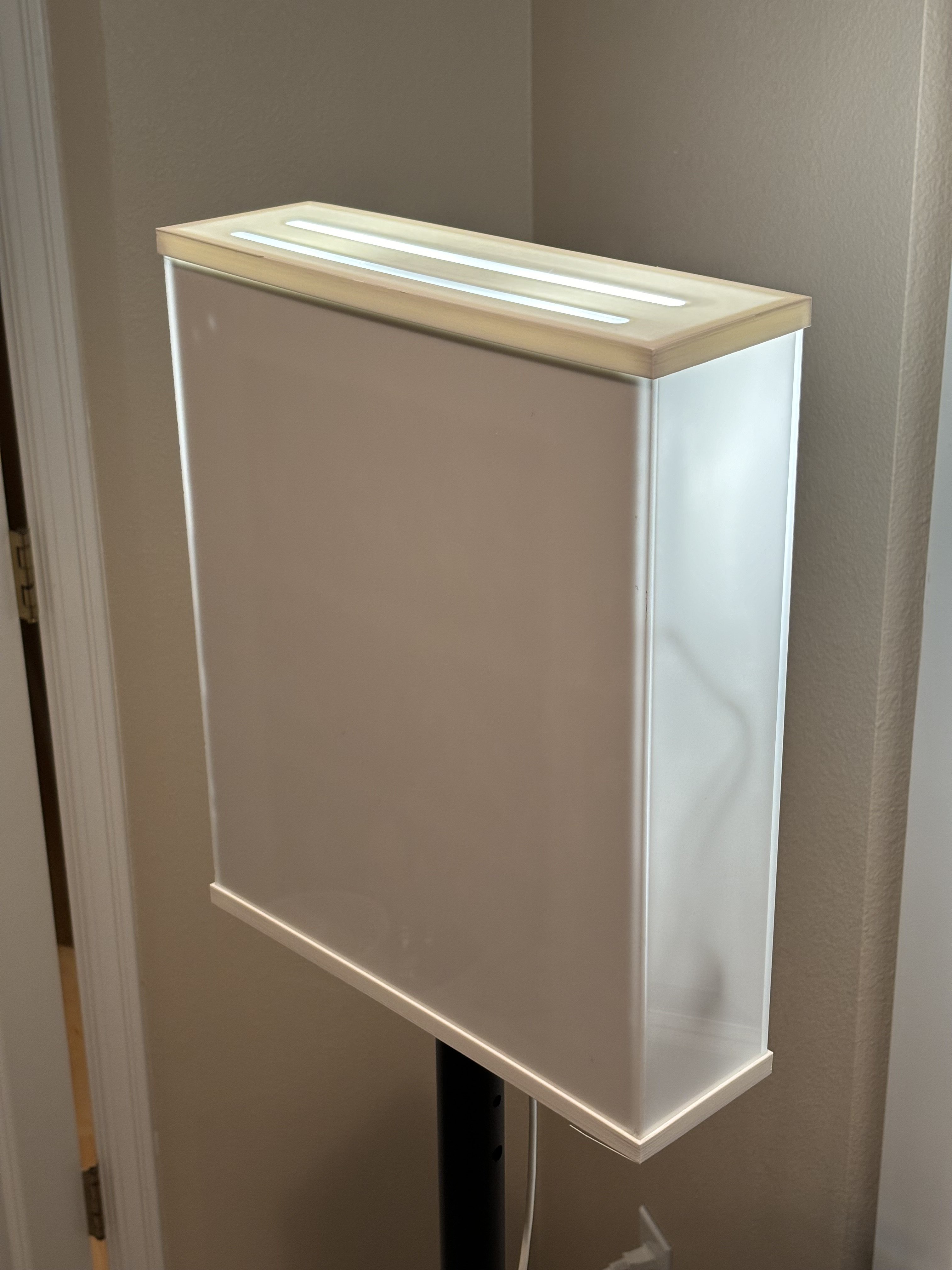
The front face with template for display mount standoffs. About 12”x14” The front face is a 12”x14” piece of 3/16” 45% cast Acrylic from TAP Plastics. The holes for the button, display, and camera are laser cut. It’s only 45% transmissive, so 55% of the light gets bounced back into the case, but it gives a nice diffused glow without excessive hot spots from the LEDs. The sides are 3/16” 9% and the rear panel is 1/8” 9%. The sides and rear are just plain rectangles so they really don’t need to be laser cut, but if you have a laser cutter, might as well use it, right?
![]()
The above photo is a rear view of the front panel sitting in the bottom panel, with all other sides of the enclosure removed. There’s also a transparent acrylic panel mounted to the display on standoffs that just keeps the wires to the Pi from getting pulled out, and prevents wires from sitting against the front panel and creating dark shadows.
The cables dangling from the bottom are an extension cord with the 24V supply for the LEDs and the 5V supply for the Pi, as well as the USB wifi adapter for the ad-hoc network. They’re normally inside the case but I moved them out of the way for better visibility.
![]()
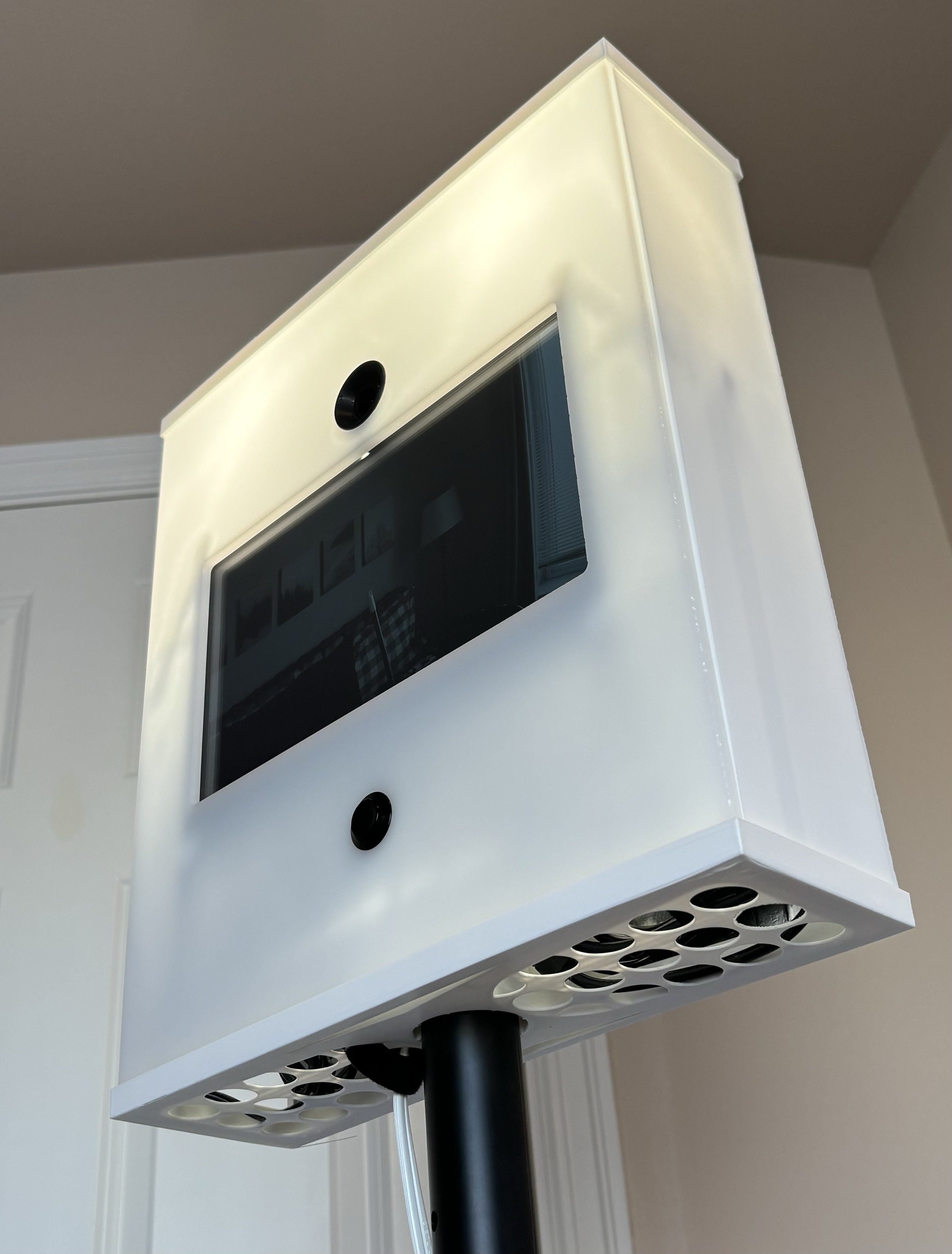
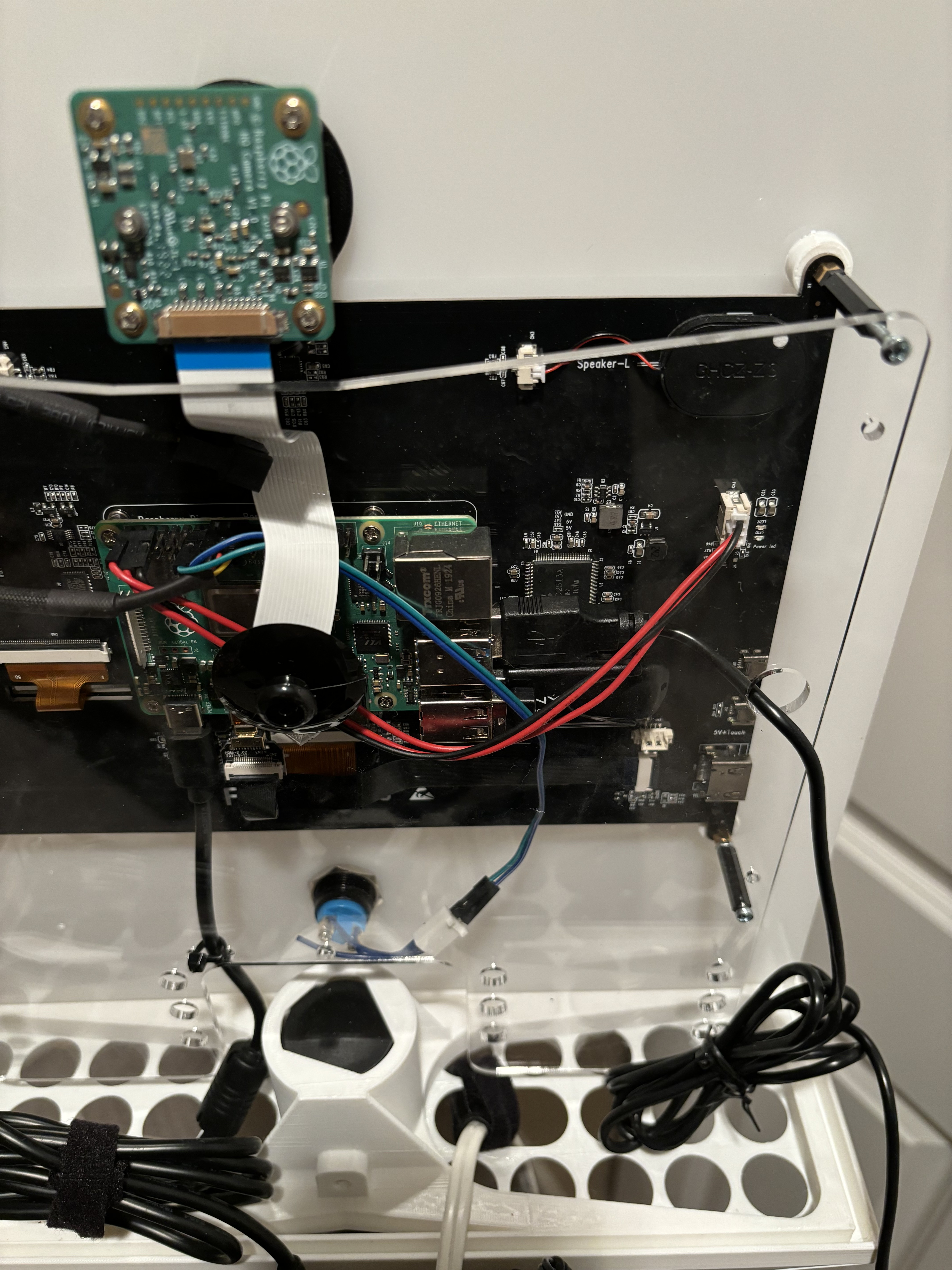
Close up of the Pi, display, camera, and button, all mounted to the front panel The LCD display already has a handy mounting spot for the Pi. You can see the Pi camera above the display, in its 3D printed holder, and the button below the display. The display itself is held to the front panel by 4 3D printed standoffs that I glued on with a slurry of acetone and ABS. I created a sketch to laser etch a template to help me glue on the standoffs so the display wouldn’t end up slanted or tilted.
![]()
Pi HQ camera with the official M12 Portrait lens ![]()
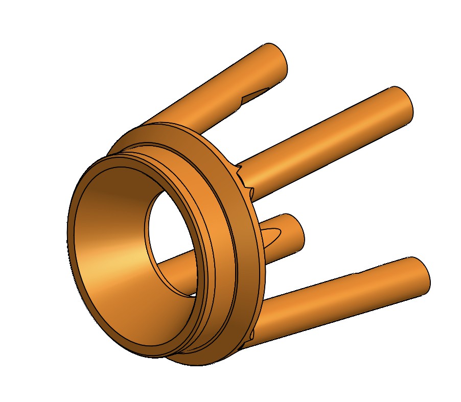
Spacecraft or camera holder? The Pi HQ camera is mounted with the help of this little holder that kinda looks like Sputnik that I printed from black ABS. It’s just an interference fit into the hole in the front plate. It’s intentionally angled a little bit downward to make our photo subjects look just a little bit better.
-
Illumination
12/22/2023 at 01:49 • 0 commentsThe current LED lighting setup is the 4th revision of what started as a $30 light ring from Amazon. Here’s the specs of what I’m using now:
- 4 high-CRI, super bright, reasonably priced ($3) Cree LEDs
- Brightness controlled through PWM by a GPIO output from the Pi
- Super simple driver circuit - a MOSFET for switching and 2 power resistors for current limiting
- 28W max power (though the heatsink probably isn’t big enough to sustain this for long)
- Powered by a cheap 24V 36W DC supply
![]()
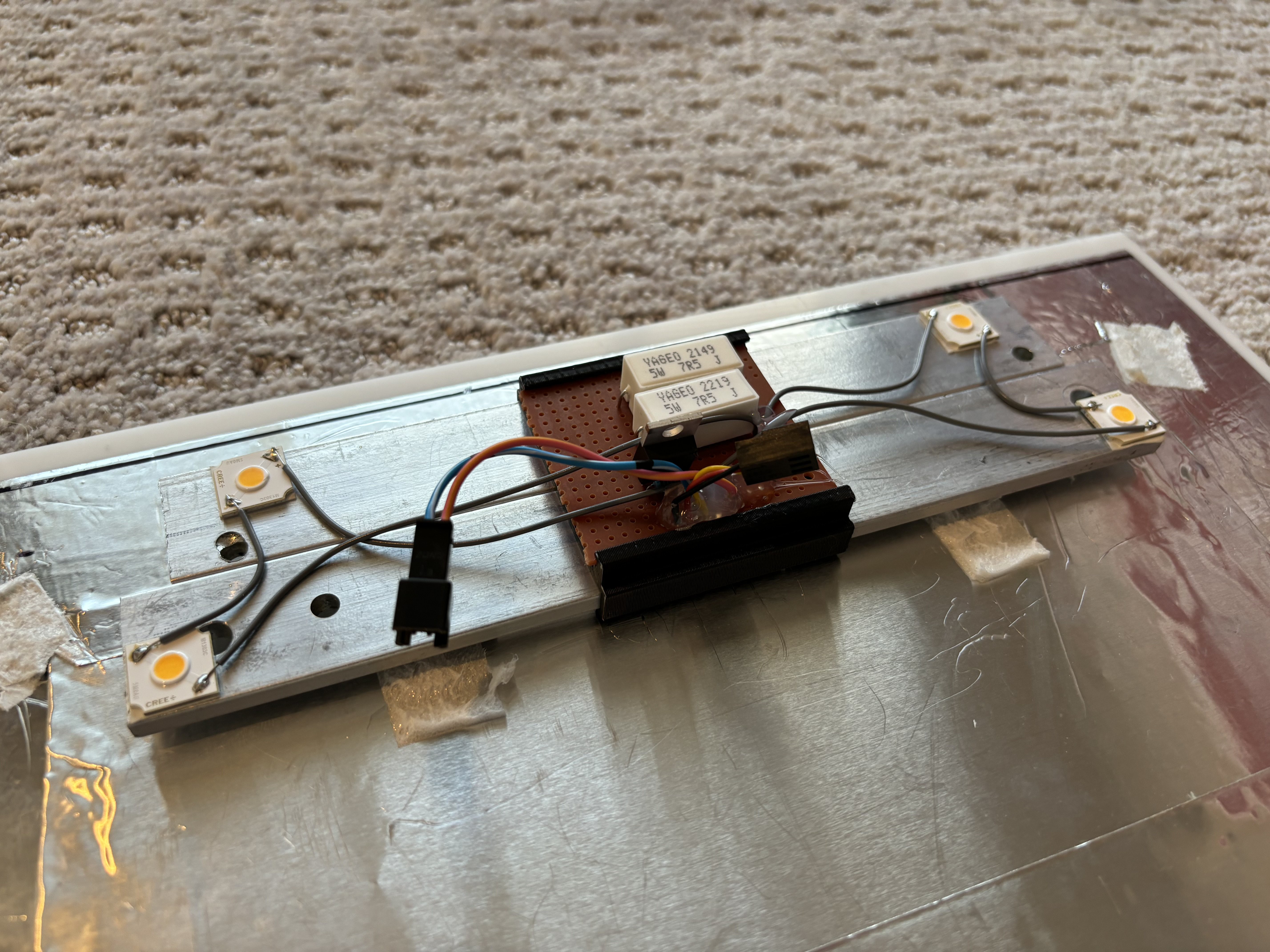
Close up of the LEDs and driver circuit, mounted to the heatsink and stuck to the rear panel of the enclosure The LEDs are mounted with thermal double-stick tape to a makeshift heatsink comprised of two pieces of 1”x0.125” aluminum stock. The heatsink is double-stick taped to the rear panel of the enclosure. In the middle of the heatsink is a 3D-printed clamp that holds a protoboard with the LED driver circuit.An important constraint to note is that the heatsink probably isn’t big enough to let the LEDs run at a high PWM duty cycle for more than a few seconds. This is acceptable for this application because the LEDs only have to be super bright for long enough to capture the photo. The rest of the time, they’re kept on at about 20% duty cycle to give the photo booth an inviting glow.
![]()
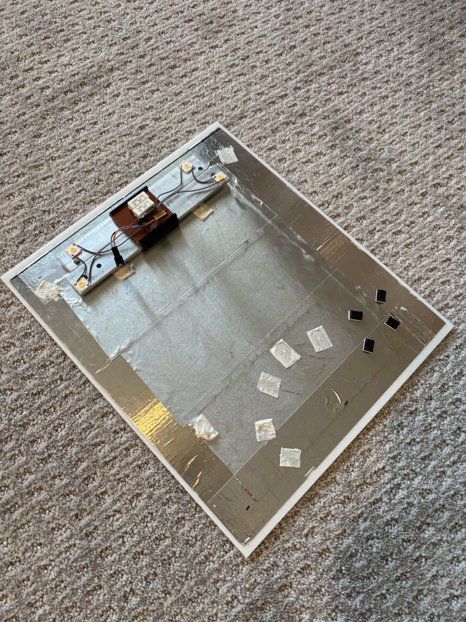
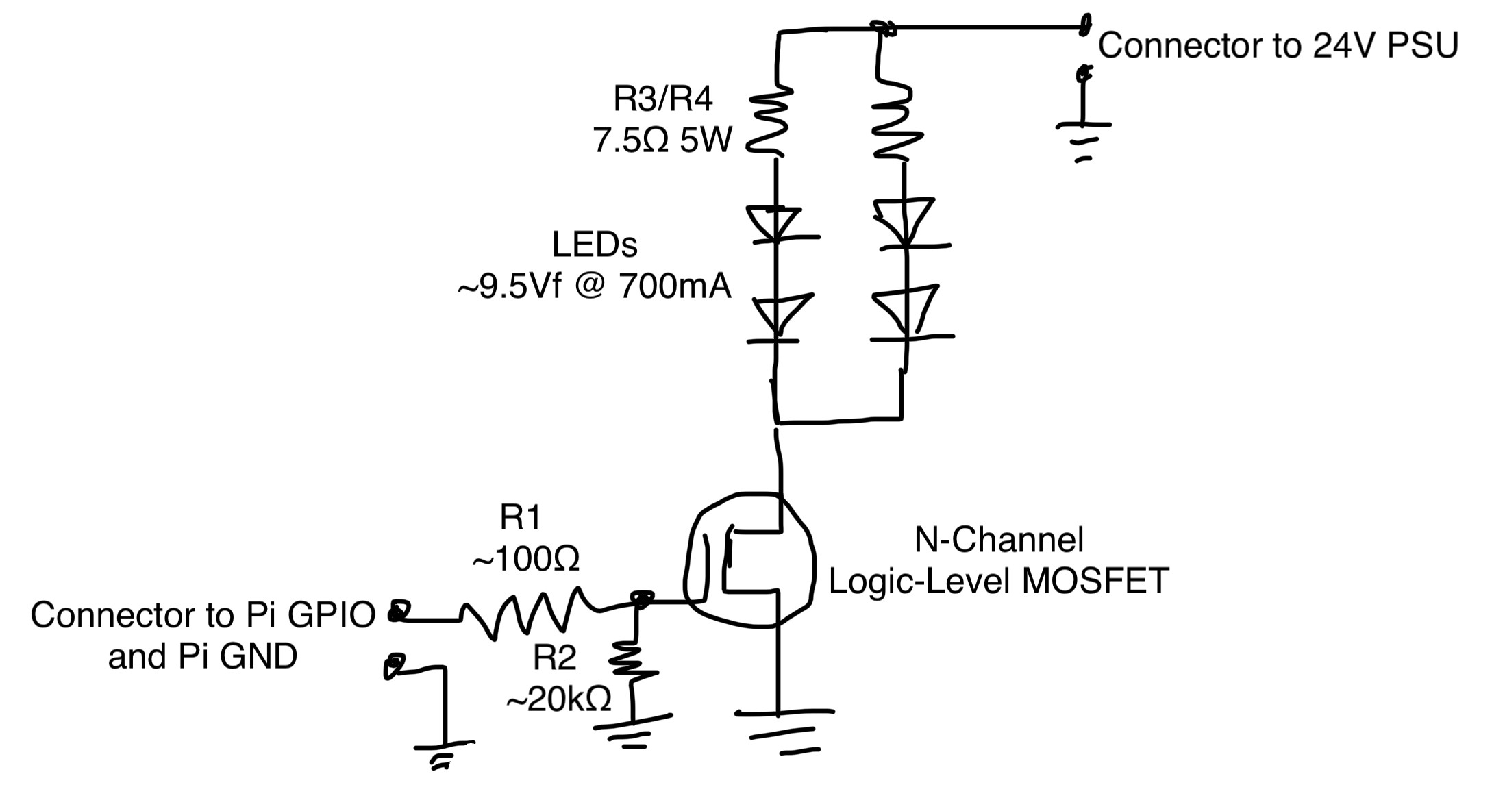
The rear panel of the enclosure, covered in reflective tape and a few random adhesive scraps Here’s the schematic of the driver circuit. As you can see, it’s quite simple, but so far it’s done the job.
![]()
R2 is very important, it pulls the MOSFET gate low when the Pi GPIO pin is not driven so the LEDs don’t stay on and burn out. The Pi GPIOs float when it’s booting up, and this takes long enough that the LEDs could burn out if they were fully switched on during this time. R3 and R4 set the current to the LEDs to about 700mA. The LED strings are switched by a N-Channel MOSFET with a low gate threshold voltage. I chose the DMT6009LCT but I’m sure there are plenty of other options that would work as well.
-
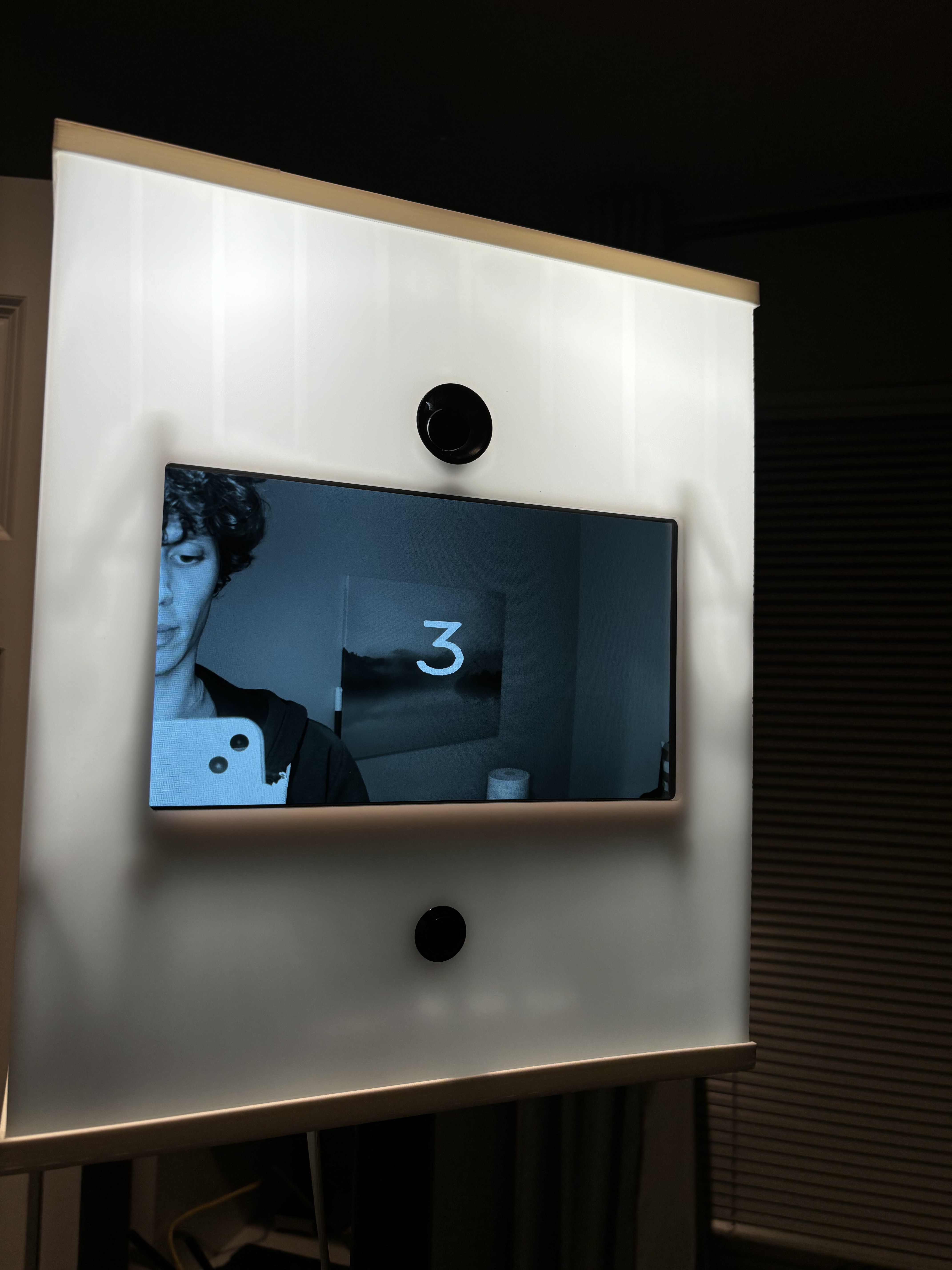
Taking a photo
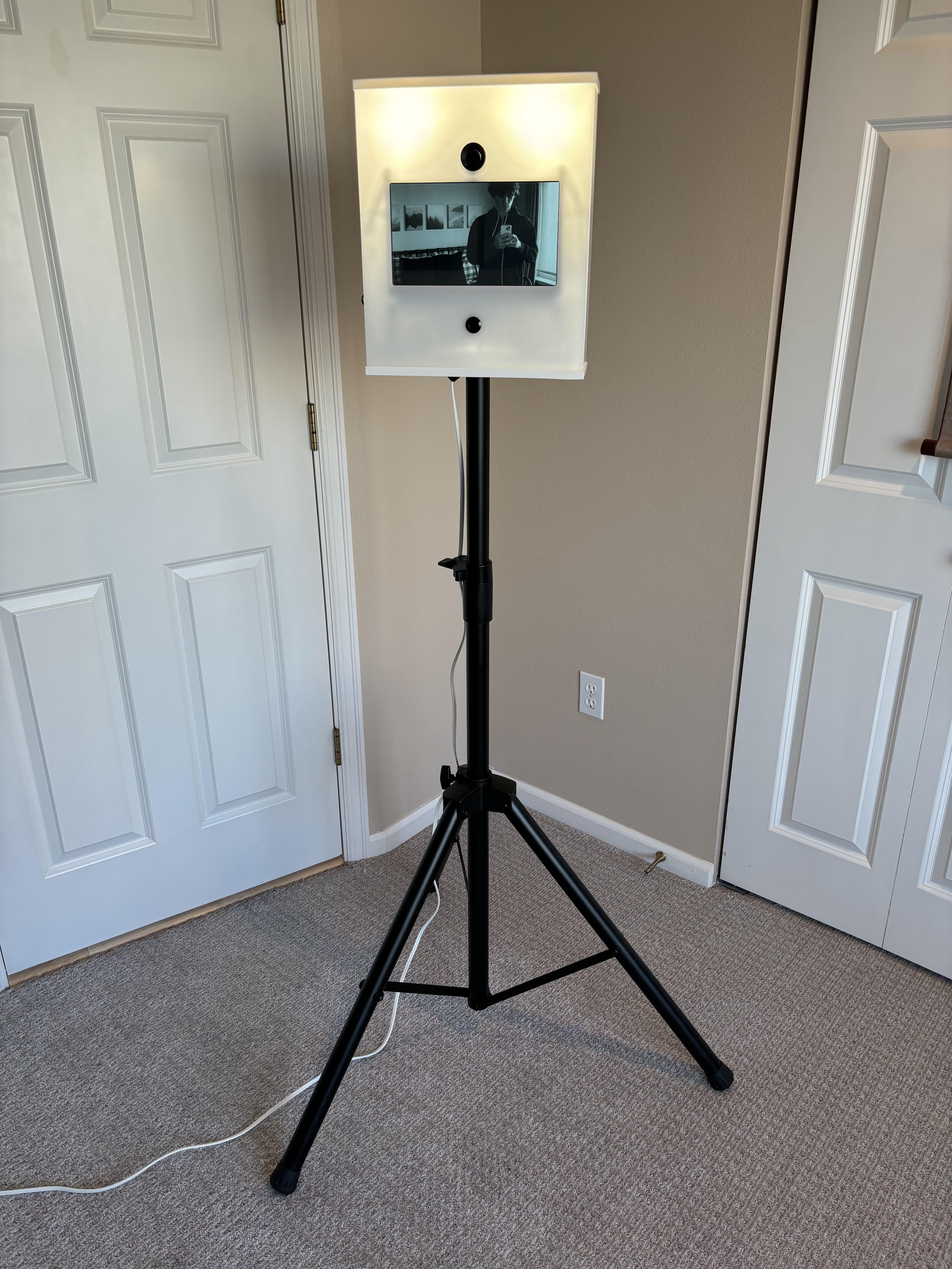
12/21/2023 at 17:05 • 0 commentsMy top priority when designing the photo booth was that it have a straightforward and appealing user experience. I figured the simplest, most foolproof interface is one big button on the front. You press the button, a countdown starts over the preview on the screen, it takes a picture, and then you see the picture it took.
![]()
The countdown ![]()
The photo is displayed after being captured I made a few more arbitrary decisions to try to up the appeal.
- The last photo is displayed until the next person presses the button, so anyone walking by will see how great the people in the last photo look, and they have no choice but to press the button if they want to see themself looking similarly great.
- The whole thing is made out of semi-transparent white plastic, and the LED illuminators are always on so it glows. What's more enticing than a mysterious glowing box with a button?
- The preview and last photo display are black and white, because aesthetics. The images are still captured and saved in color.
Pi 5 Photo Booth
Designed to be as user-friendly as possible and take great photos, without breaking the bank