Making the face plate took a long time of planning... I knew I wanted brushed aluminum from prior experience but I did not have a good way to cut and machine it. Over the course of building a few amplifiers, I procured both a router and table saw. This gave me the ability to machine everything needed.
The process was roughly as follows below:
Cut a sheet of aluminum I purchased from Speedy Metals online. I oped for 1/8" here. I did this on a 10" portable table saw using a blade designed for metal.
Used masking tape on the front and measure out a hole pattern for dials and switches. Then use a center punch and drill out the holes to the size needed.
Using a router with a carbide 1/8" endmill, router out the slots for the 5 band EQ. This was by far the most difficult part. I found the key is to go slow, and take it in multiple height passes. Some WD40 as lubrication also made a huge difference in preventing the chips from sticking to the bit during machining. I marked the top and bottom of the slots with sharpie, and used a block of wood clamped to the router table as a guide for the edge of the aluminum. I used a 1/2" square dowel to space the aluminum plate and move the wooden guide over to keep a consistent 1/2" spacing of the slots.
Using a similar approach, on the back side, route out half depth for potentiometerand switch keys that prevent them from rotating...
To give a brushed aluminum look, start with 80 grit sandpaper till major blemishes are removed, then work down to 120 or 150 grit. Only sand in 1 direction, I find the long direction works best. I also found putting 2 screws into a board aligned with two of the holes on the plate gives a good method to hold the face plate in place as you sand it. Also - I always wet sand, I would recommend it.
Coat the face with a few layers of polyurethane to smooth it out and protect the aluminum brush finish. This also makes it easier to write on with paint pen.
I used oil based paint pen, because I wanted to put 1 layer of polyurethane over it for protection, it did not smear. I think water based would be ok as well. Just give either option a few days to dry well first.
Cheap Tubes? Yep, at least before Russia invaded Ukraine.
eBay has loads of cheap Soviet era tubes from the late 70's to the late 80's. The quality in my experience has been solid, and this is due to most of the surplus tubes being military grade, as well as soviet countries using tubes long after the west stopped due to a lack of home grown silicon manufacturing capabilities (An example being the Mig-25 fighter jet of the 1970's was designed to use vacuum tubes instead of transistors as western equivalents were already using. What this all means is Soviets made decent quality tubes even into the 1980's.
Pre-amp Tubes
Pre-amp tubes, specifically the ubiquitous 12AX7 has a soviet equivalent, the 6N2P-EV / 6Н2П (Cyrillic). It is not pin for pin compatible though if your amplifier has a 6.3V heater (Most do) then you are probably in luck. Depending on the exact implementation most likely 1 pin needs to be wired differently. The change is trivial if you have a point to point wired amp or a two layer PCB you can easily cut a trace. These tubes I have found are excellent quality, and usually 1/10 to 1/5 the price of an actual 12AX7. I assume this is due to very few existing radios etc. are wired for the soviet tubes anymore...
One item of note is the Soviets only have an equivalent for the 12AX7, there is no concept of the AT or AY tubes, I guess less was more during that time...
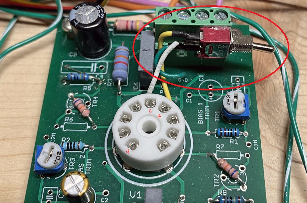
My prototype boards, I ended up adding a switch that changes one of the pins between 6.3V (Western) and Ground (Soviet), this allows me to use any tube with minimal work.
I have pin 9 wired to ground, and pin 5 wired to 6.3V, the toggle switch allows me to toggle pin 4 between ground and 6.3v to work for either a US or Soviet style tube.
There are a lot of diagrams of varying clarity online about doing this, here is one.
Power Tubes
You can find power tube drop in replacements, they are pin for pin compatible and typically nearly specification identical. The unfortunate thing is this makes them worth a bit more, so a set of Soviet power tubes may cost you still 1/2 the price of a western equivalent. I have found the bias points vary more then modern tubes, but maybe I have been unlucky, as long as you bias correctly everything will sound fine.
6L6 <=> 6N3C / 6P3S
6V6 <=> 6N6C / 6P6S
EL84 <=> 6P14P-EV Note: "-EV" designates military spec.
I'll assume you know what reverb is if you are here, but what is a reverb tank? Modern effect pedals use electronics to create short delays creating the effect of sound reverberating around a room.
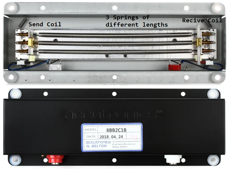
Originally the reverb sound was created by sending sound-waves down a physical spring, and reviving them at the other end, causing a delay and muddying of the sound. Modern digital systems mimic this really well, but the analog systems are not very expensive so often guitar amps still use analog spring tanks like the image below.
Here is a decent page about all this, my circuit is based strongly on the solid state examples given.
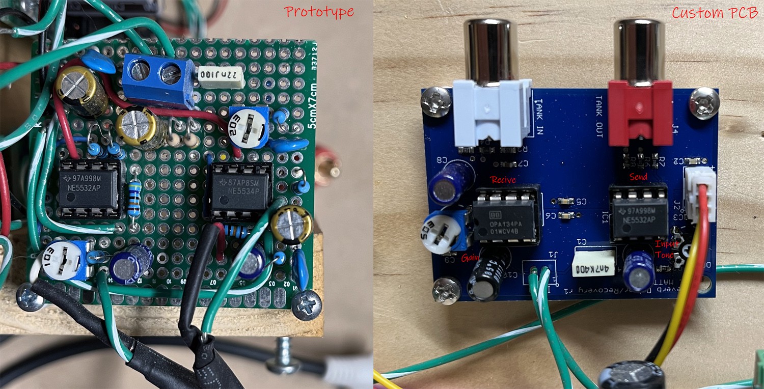
To drive these mechanical systems requires a low impedance source, and to receive the return signal requires a high gain stage. Like most modern amplifiers I chose to use solid state components (Op-Amps) here because it is not critical to the drive or sound of the amplifier, and it is significantly cheaper, smaller and easier.
It is also worth noting reverb tanks technically have a mounting direction, mine is upside down in the head unit I have pictured here. Looking at the unit itself, I'm not sure how much of a difference it makes, it appears the chassis has multiple mounting points that would help fight gravity in different mounting positions, I made no changes as the springs in this orientation appear to still be centered inside of the transducers. It sounds fine, but an A/B comparison was not done.
Below is the resulting prototype board, and the final PCB, and the schematic follows.
The lead channel went through multiple renditions, a lot of things did not sound good, or just resulted in adding noise. Eventually I came to the conclusion that more gain stages does not make it sound better, and the multi gain stage amps you see actually have a lot of tone shaping and phase delay happening, hence the need for the stages, not just for extreme gain.
I ended up using a single 12AX7 with two sets of tone shaping. The tube is setup as a warm / cold clipper.
The 1st stage has a low cut to reduce the bass signal. This helps keep a more even distortion across the spectrum instead of power cords that are over driven and mushy, while the high end is still sterile sounding. This is implemented via C17 shown below, the 0.68uF capacitor equates to ~120Hz high pass mathematically. It also has a warm bias, so you can start overdriving the tube with not a lot of signal.
The 2nd stage has a bass boost to recover some of the bass you want with a power cord. This is implemented in a less then ideal way, it has an RC network (R12 C16) in parallel with R32, this reduces gain at this stage as the frequency goes up. This stage also adds distortion from running near its cutoff region, it has a bit of non linear amplification as the input voltage swings low.
In order to help create a quieter lead channel I also reduced the series input resistance to each tube stage. Typically you see 68k grid resistors (R26 R35) on amplifiers going into each tube, this works with ~150pF of internal tube capacitance to make a low pass filter ~10Khz to stop the tube from amplifying non audible signals. By adding additional capacitance in parallel with the tube (C5 C18) you can shrink the grid resistors, and reduce the noise they add. The buzz you hear on a high gain amp is mostly coming from the grid resistors, and 60Hz from the mains transformer (which I do not have).
Shown below is the approximate circuit used for the lead channel, the simulation shows this gain stage in isolation, so all the tone shape you see is from just what is visual.
This should have its entire own project on HackaDay, and maybe soon it will.
Usually a tube amp needs a high voltage transformer, I decided to attempt something different here since early on I was unsure about the final voltage I would want, as well as wanting dedicated 15V rails for op-amps and other lower voltage circuits.
I started development of a solid state power-supply in 2018. Early on I tried a cheap eBay high voltage module, after destroying two at a very low load I decided to move forward and make my own.
Some of the requirements that developed over time:
24V input voltage so I do not need to deal with 120V AC line isolation.
Variable output voltage: 250-360V, 28W
Heater Voltage: 6.3V, 3A (With Softstart)
Negative Bias voltage: -30V
Op-Amp rail voltages: ±15V
Below is the first revision of the board, it only had a high voltage flyback and a buck converter for the heater. It lacked the 15v regulation and negative bias outputs that I would later want. The layout was not great and I had stability issues due as well.
For these kinds of requirements, the only option was to wind a custom transformer with multiple windings. Winding a flyback transformer, and air gaping it with Kapton. Later transformers used parallel primary windings to reduce the skin effect losses, as well as multiple auxiliary windings for the negative bias and op-amp voltages.
Lots of engineering, math, testing and measurements later... I eventually ended up with this:
A roughly 60W power supply 88% efficient under nearly full load. meeting all the requirements above. Looking back I would now design the supply to run off of 120V instead of 24V. I would also move to a GaN switching FET. But this works...
 Collin Matthews