mkdxdx
-
Final touches
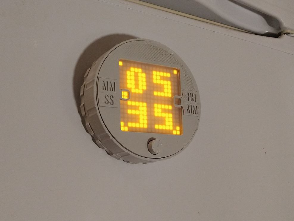
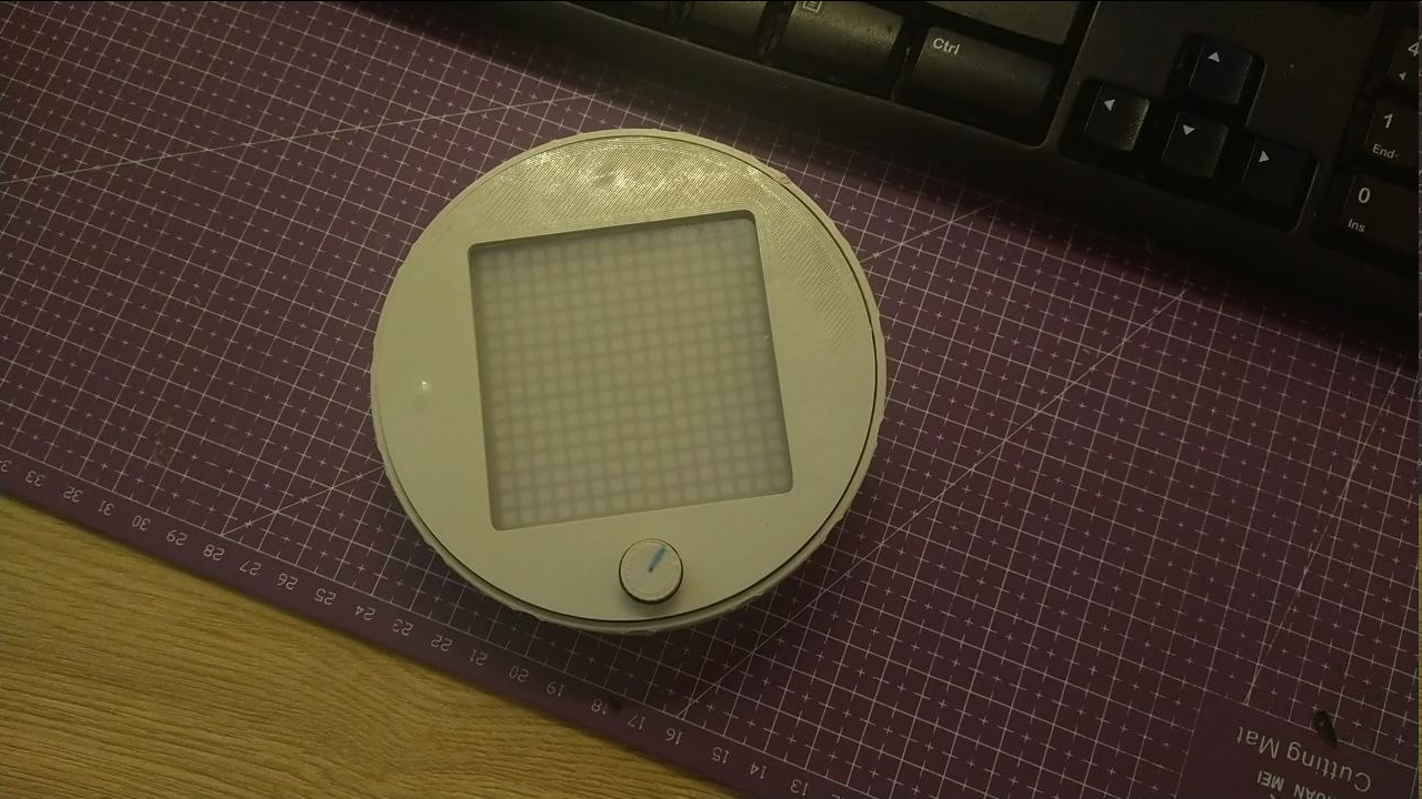
01/20/2024 at 22:21 • 0 commentsI've changed indication that shows either MM:SS format or HH:MM and added few hints on the dial itself. Adds to the character a bit.
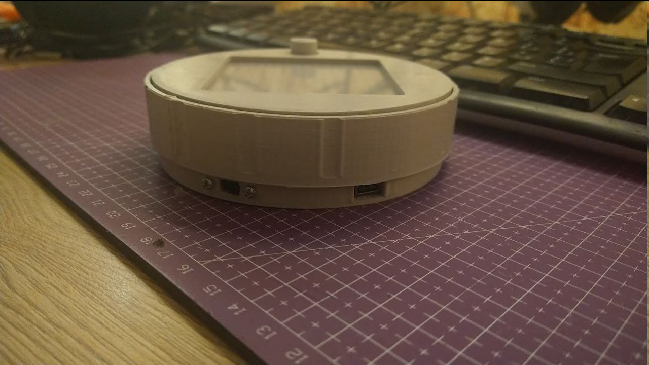
Also added more ergonomics by making more ridges on the case to have a sure grip when dialing time into the thing.
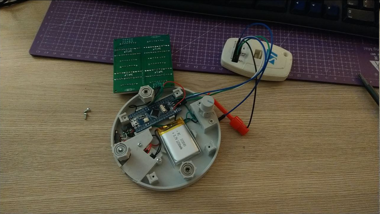
I've ditched the idea to use PWM to generate sounds in favor of an active buzzer, buzz of which is modulated by the same PWM, albeit at around 2Hz to mimic a fire alarm. I think there is no chance i could achieve the same loudness as these little fellas can do - not with simple schematics atleast, you would need a bridge driver to push the aler further than a few rooms.
So I bodged a 2n2222 transistor with few supporting components so not to burn the GPIO and here it is - his loudness the buzzer, blowing right into the space where battery charger board is located - it has a proper opening to the world for sound to come out to.A new addition - instead of 6 weak magnets to attach the timer to fridge door, I've decided to use 4x 18x3mm neodymium magnets, each providing around 2,5kg of force. Enough to lock it in place and provide enough grip to rotate the dial without using another hand. Neat!
And you can't imagine how hard it is to make a picture like this - these fellas do not want to stay in place without some adhesive help, always seeking to reunite with their attractive brethren.And to transfer the whole holding force to the primary case - it was redone to have recesses for heat set nuts, because threading plastic will probably not work when there is so much force pulling it in other direction.
And boom, there it is.
Although the precision leaves something to be desired - i use systick as a primary timing source and it can and will drift a bit. Timer was capped at 24h mark and even then it will probably drift to maybe a minute. It is still completely serviceable for meal preparation timing - no more burnt patties for me, yay.
STM32F103 has RTC and this board also has LF quartz attached to it - so there might be an update to use that as a timing source.
Also there is no power efficiency consideration - CPU is always active, DCDC effectiveness is probably subpar, so 1200mAh, as i estimate, might live for around 8-10 hours best. Though it is a question of when undervoltage circuits will kick in - the battery has one on it, and TP4056 board also has another one on it, so go figure. Maybe another day (probably not because i hate working with MCU low power modes - always break the debugging session or makes you read the documentation properly).
Until then - this is how the project is going to be paused at.
-
Keeping time
01/19/2024 at 01:36 • 0 commentsI think I've got basic controls and operation modes, and I guess.. there isn't much more too it?
It has slow animation mode (when it has more than 1 hour set). Also indicates that HH:MM (hours over and minutes under) format is active by two rectangles to the sides.
![]()
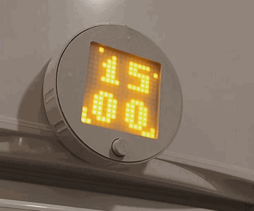
It has fast animation mode (when less than 1 hour is left)
![]()
It has blinking animation when time is up
![]()
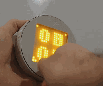
And here is how you set it up. You can rotate main dial for large time leaps or spin the button for more precise control. Pushing it starts the countdown, pushing it again pauses the countdown. Long press resets paused countdown back to time setup.
![]()
Time to add some buzzing action.
-
Taking shape - the shapening
01/17/2024 at 20:11 • 0 commentsSo previously I've tried to make idler and encoder wheels to just have smooth surface but cover it with some friction tape and it did not work - it created tensions where they were not needed and vice versa, provided no traction where it was necessary.
So now I'm going involute gear path, although I suck at it as with CAD generally.
Couple case iterations and one assembly later I have something that reeks with "a weekend project" vibe - wires everywhere, battery being held only with a double sided tape - the stuff we love, in other words.
It does not have buzzer circuit though, I'm still waiting for DC filter capacitors to arrive.
Anyway, here is some bonus gear action!
Now onto breathing some life into this. -
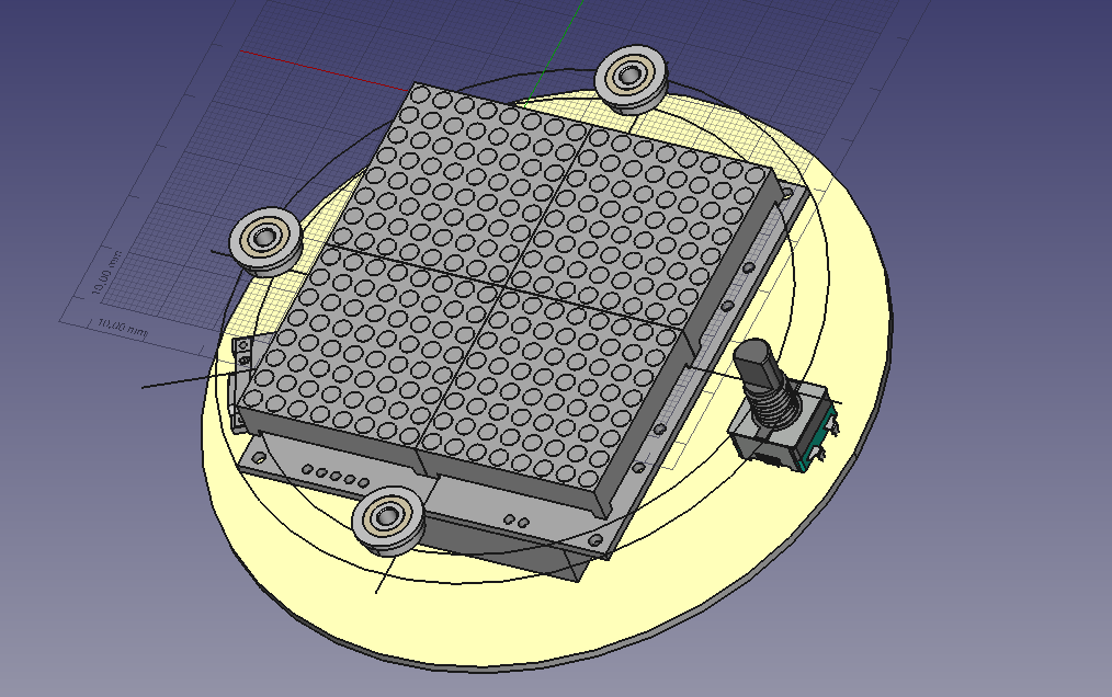
Taking shape
01/15/2024 at 00:22 • 0 commentsGot first-ish iteration of case rolled out.
Initially the idea was to print idler wheels and main encoder wheel to then be taped by something that provides enough friction to stay in place and not give much way and then also transfer rotation to encoder.
Turns out it does not really work that way. You can tape your wheels alright, but you probably won't be able to do something like that to an inside diameter of the bezel wheel - tape will not stick in that configuration.
So I guess i will have to calibrate my printer and dip my toes into gear design, however cursed that sounds for now.
![]()
-
Preface
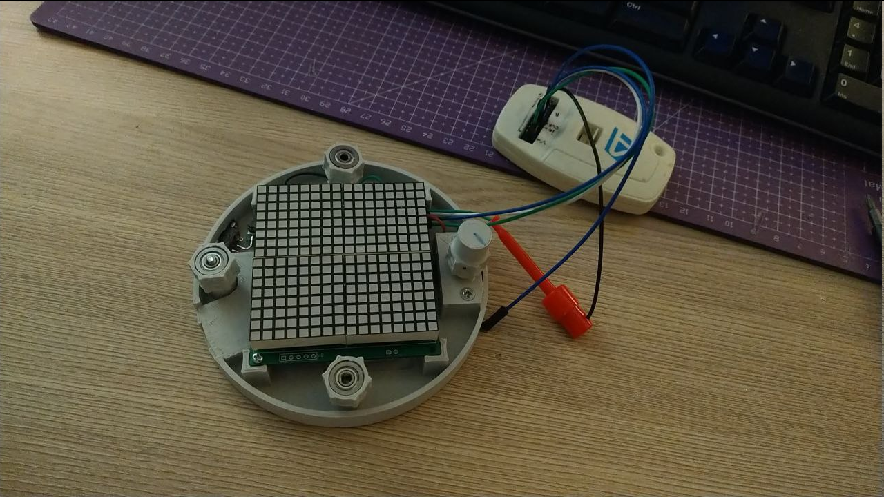
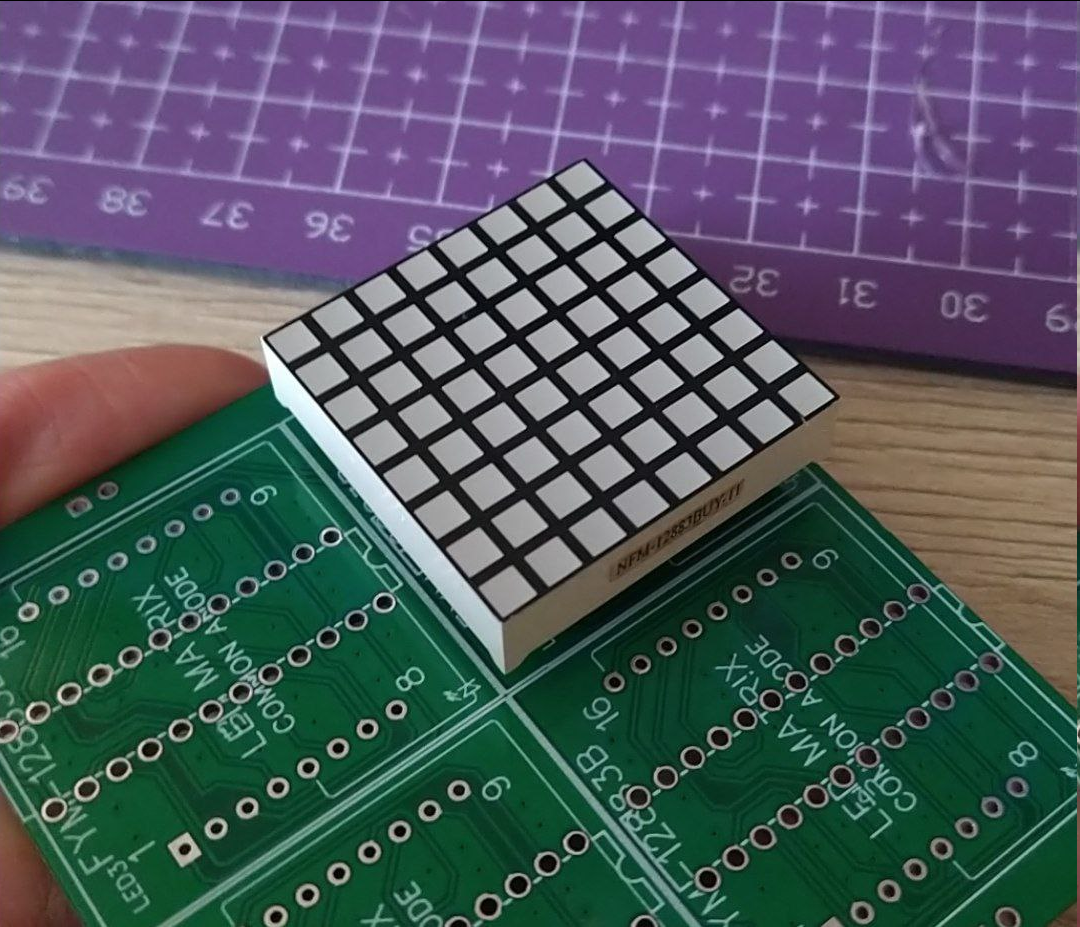
01/13/2024 at 09:28 • 0 comments- There was a simpler time when I was having this sudden urge to pay a visit to our local flea market for different stuff, which usually ended with me going home with such stuff - namely some electronic parts, enclosures, etc. That is how i ended up with a few dozens of LED matrices - some were torn out of marquee signs (not by me), some were just surplus the seller got somewhere else. And they need some use now.
- After my previous public projects I decided to take on something really simple functionally, and, if possible, mechanically. So I can better orient myself in regard to scope, time, materials etc.
That is how REST project series shows on my DIY scene - "RElatively Simple Things".
And this project is also an answer to a question of "what to do with all these LED matrices, layout of which does not fit de-facto standard MAX7219 arduino modules that people toss around?"
They glow juicy yellow, btw.
So, first i went to JLCPCB to design and fabricate several carrier modules - different versions, actually. I made 1x, 2x, 3x, 2x2, 3x2, 5 of each, just so I could reuse them later after this project also.
There is also this hilariously tragic story of how I ordered 25 pcs of DIP MAX7219 a long while ago (prior to designing the modules) from aliexpress and all 25 of them turned out to be dead.But module PCBs are already made, what do I do now? That's right - order some more LED drivers, because matrices won't drive themselves!
New materials arrived, i verified that new chips do work and matrices work as expected (although current schematic version has decimal point pin driven last instead of first - so in this regard my module is not compatible with arduino-like MAX7219 libraries), and it is time to pull a concept together.
I wanted to design a simple kitchen timer with a rotatable bezel and which also can be magnetically attached to, say, a fridge. Not really an original idea - i saw even a DIY version that uses segment digital display, but nonetheless, this one is better at being my own take at it.
Now what's left is to arrange things in a way that they are nice and snug and won't bite each other when bezel is rotated. Instead it has to drive encoder shaft with either gear teeth, or some kind of friction (will a hockey tape work?).
 I've ditched the idea to use PWM to generate sounds in favor of an active buzzer, buzz of which is modulated by the same PWM, albeit at around 2Hz to mimic a fire alarm. I think there is no chance i could achieve the same loudness as these little fellas can do - not with simple schematics atleast, you would need a bridge driver to push the aler further than a few rooms.
 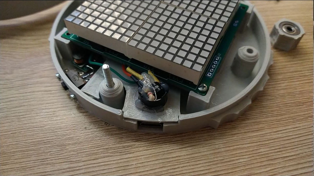 A new addition - instead of 6 weak magnets to attach the timer to fridge door, I've decided to use 4x 18x3mm neodymium magnets, each providing around 2,5kg of force. Enough to lock it in place and provide enough grip to rotate the dial without using another hand. Neat!
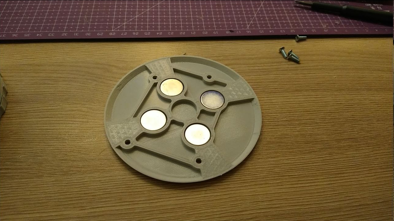 And to transfer the whole holding force to the primary case - it was redone to have recesses for heat set nuts, because threading plastic will probably not work when there is so much force pulling it in other direction.
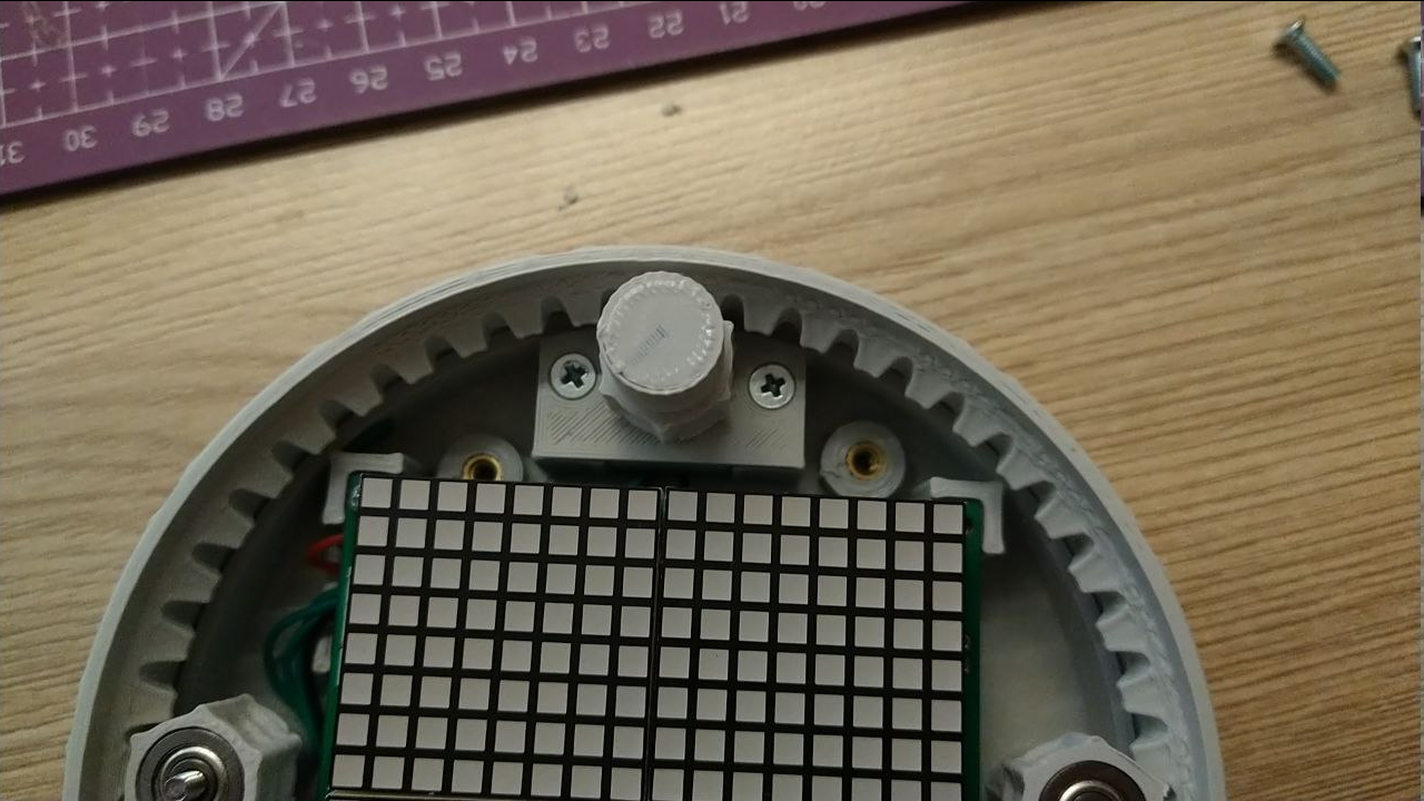 And boom, there it is.
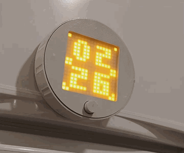

 It does not have buzzer circuit though, I'm still waiting for DC filter capacitors to arrive.
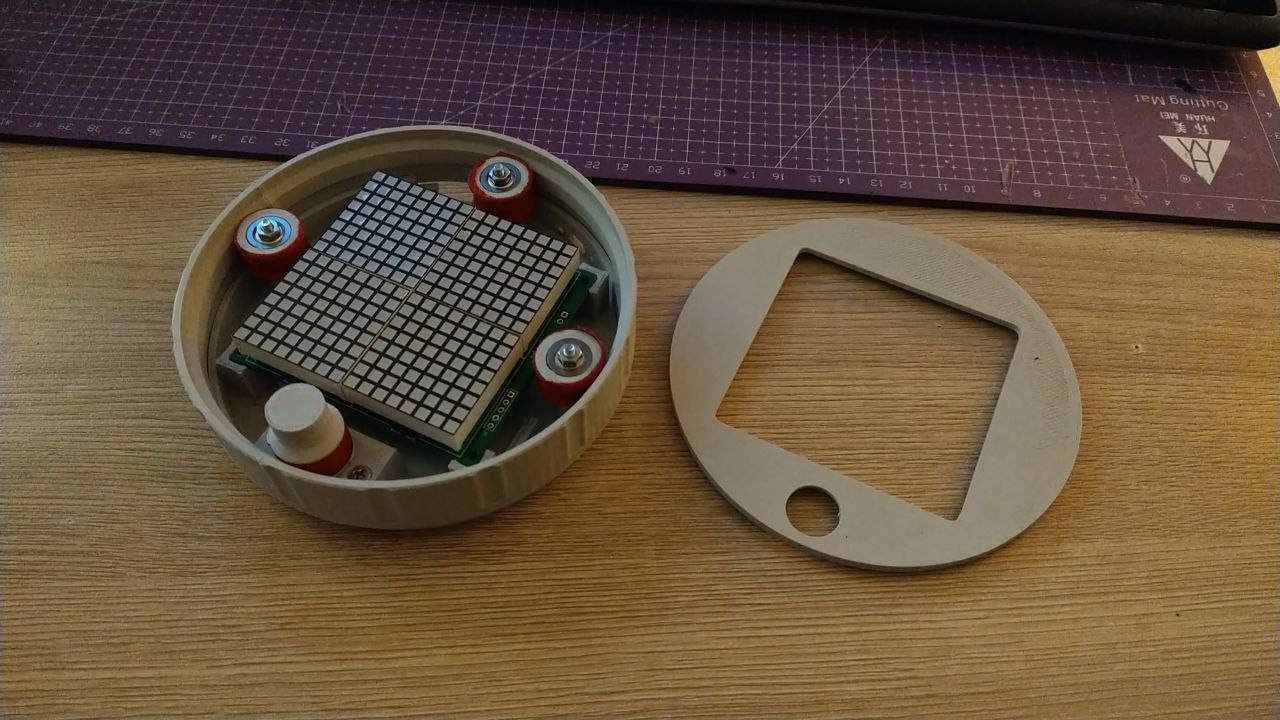
 So, first i went to JLCPCB to design and fabricate several carrier modules - different versions, actually. I made 1x, 2x, 3x, 2x2, 3x2, 5 of each, just so I could reuse them later after this project also.
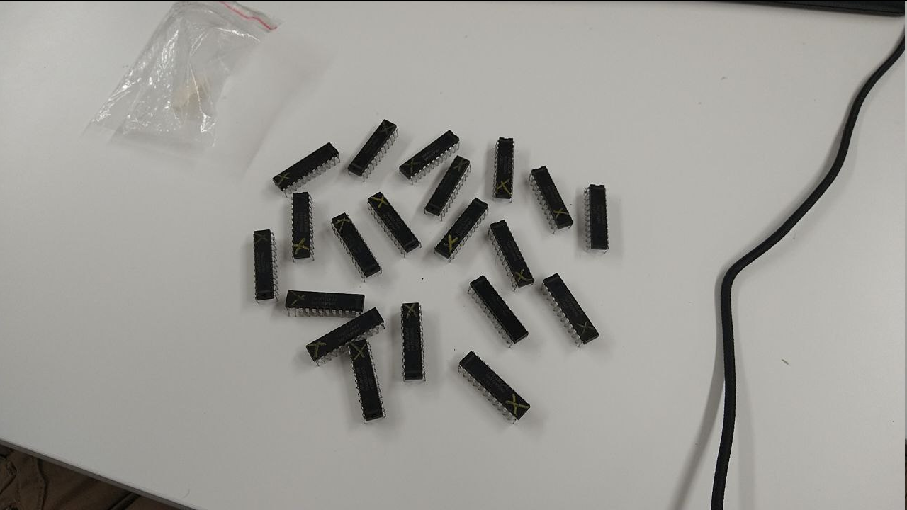 But module PCBs are already made, what do I do now? That's right - order some more LED drivers, because matrices won't drive themselves!