 Capt. Flatus O'Flaherty ☠
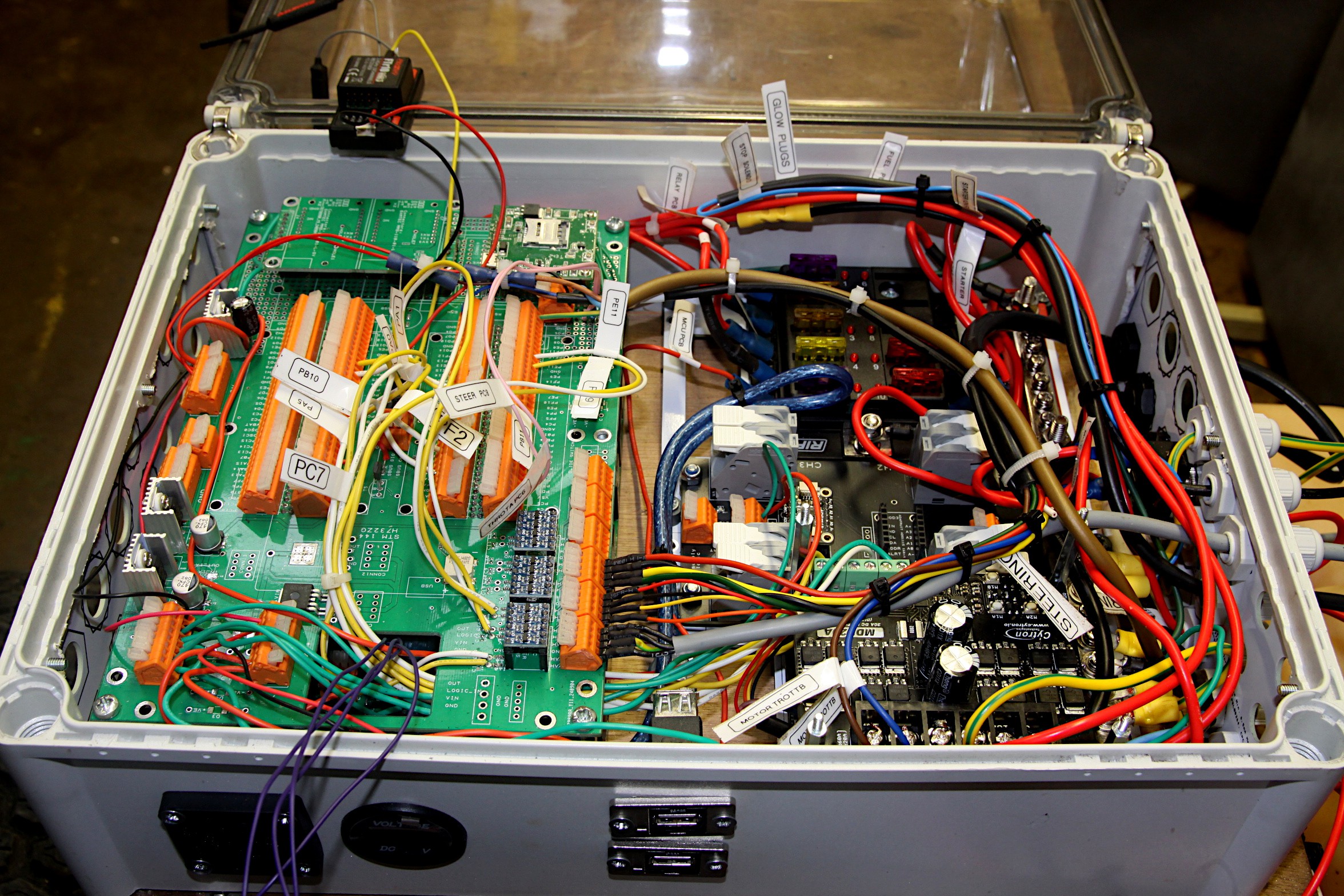
None of the previous logs have really gone into any detail about the left hand green MCU PCB, so here we go! The main feature of the board cant actually be seen as it is slotted onto the underside of the board, namely the STM Nucleo H723ZG MCU. There's absolutely no point in having it on the top surface as it just takes up lots of space which is better occupied by connectors. There can be seen 4 rows of orange Wago connectors on the top surface in the photo below and these correspond to each and every one of the 144 pins on the H723ZG. The board has been carefully designed so that all the pin designations eg PC7 can be easily read on the PCB silk screen to help wiring up the system.
There's another row of these orange connectors on the right hand side and these have permanent connections to 3 banks of blue logic voltage shifter modules which convert the 5V from the 3 electric actuators (steering, throttle A and throttle B) to 3.3V, which is safe for the H723ZG pins. On the other side of the logic level shifter are yellow and white wires soldered in for the quadrature encoders. Other yellow and white wires connect from the MCU direct to PWM and direction terminals on the black Cytron motor control modules on the lower right hand side of the box.
On the very top left on the green MCU PCB is a small green GPS daughter board which is waiting for it's GPS modules to arrive. To the right is a 4G modem waiting for it's sim card to be inserted. Other than this there are two 5V and one 3.3V regulator with large capacitors on the 12V input side. There's also four simple voltage divider circuits, which cant be clearly seen, for changing the 12V signal from the inductor sensors to about 3V for compatibility with the H723ZG MCU.
If we look really closely, we can see a through hole transistor in the middle of the green PCB which is used to invert the signal from the SBUS receiver so that the MCU serial bus can recognise the data flowing in. The SBUS receiver itself is the black box perched precariously at the top of the box and is due to be moved to somewhere near the top of the machine with cables to extend the SBUS connections. The 4 purple wires at the lower edge of the box are for actuating the 4 engine relays as demonstrated in the previous log (engine stop solenoid, fuel pump, glow plus and starter motor) and are waiting to be assigned pins on the H723ZG.
Discussions
Become a Hackaday.io Member
Create an account to leave a comment. Already have an account? Log In.