 Capt. Flatus O'Flaherty ☠
Most of the circuits used in this system are relatively simple due to it's modular construction, so more complicated circuits such as the MCU are provided on seperate modules, often from separate suppliers. For example, the MCU module is supplied ready to go as a STM Nucleo H723ZG. The main consideration in this project is the overall circuit diagram, which is extremely flexible and can be re-wired in seconds. We don't provide a 'digital' version of the diagram yet as it takes too long to make edits, instead, the diagram is drawn by hand and we create new copies using old fashioned light box technology which takes about 10 minutes to create a new updated version rather than 3 hours + for a digital one. For us, it's appropriate use of technology at this point in time.
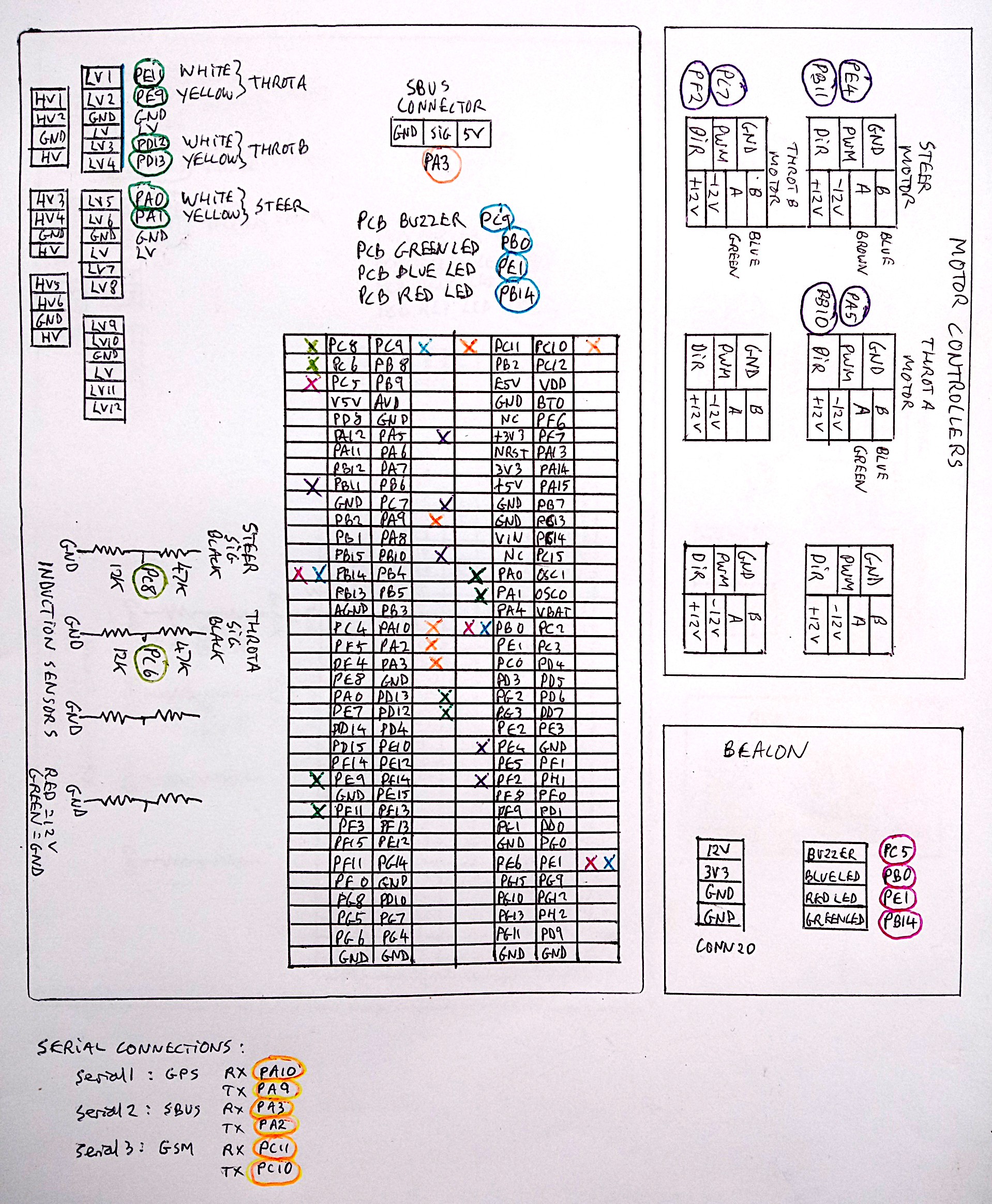
As can be seen, the wiring is extremely simple. There's colour coding for different types of connection eg orange is used for serial connections. The only permenant connections are for the 3 PCB LEDs on the MCU board and the PCB buzzer. The LEDs replicate what's on the STM Nucleo module and all of them can be disconnected and re-allocated with a bit of soldering on the PCB and removing solder bridges on the STM Nucleo H723ZG. Notice there's no connection lines drawn in the diagram except for the four resistor bridge ciruits. This is to keep the diagram neat and tidy! Also, there are no connections indicated for the relays yet as this is work in progress.
Discussions
Become a Hackaday.io Member
Create an account to leave a comment. Already have an account? Log In.