 The Lab Guy
-
1Acquire a PicoMiteVGA computer
If you don't already have a working PicoMiteVGA lying around, then jump on ebay and search for "picomite".
The search results should turn up multiple options for you, ranging from bare PCBs from around £10, to fully assembled and running boards for £25. Most of the lovely ebay sellers even deliver for free!
If you want to solder on your own components or get your PCB made, hop over to Geoff's Projects - PicoMite VGA page for full details.
Don't forget to download and flash the Raspberry Pi Pico with the PicoMiteVGA firmware.
-
2Connect and Test the PicoMiteVGA
Assuming that we have our working PicoMiteVGA, a PS/2 keyboard and a VGA to HDMI converter, let's get started.
Make sure that the Pico is NOT connected to a USB port on your PC or powered by any other means.
- Plug in the PS/2 keyboard
- Plug in the VGA to HDMI adapter
- Connect a USB cable to the side of the VGA to HDMI adapter
- Connect an HDMI cable from the VGA to HDMI adapter to an HDMI monitor input
- Turn on the monitor and select the correct input, if necessary
- Power on the VGA to HDMI adapter
- Power on the PicoMiteVGA
If all is good, you will see the keyboard LEDs blink and then settle on NUMLOCK and the PicoMite VGA BASIC banner and a blinking cursor on your HDMI monitor!
If you get nothing, you could try:
- Connect the PicoMiteVGA video output directly to a VGA monitor
- Try a different HDMI monitor or TV
- Power off and then power on the Raspberry Pi Pico
-
33D Printing the case parts
Retro Style Home Computer Case by thelabguy - Thingiverse
https://www.thingiverse.com/thing:6444015
Assuming that you have the same keyboard as me, the easiest thing to do will be to download the STL files from Thingiverse, using the link above and send them to your printer.
Remember to print off enough "pegs" to align and join all the pieces to each other.
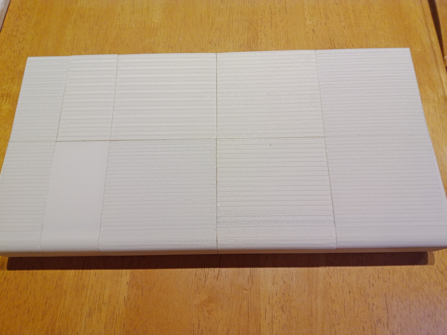
I printed the case body parts in their horizontal orientation, with the top surface horizontal and the ramp at the bottom sloping up, AWAY from the print bed. This meant that the top of my retro home computer had a nice smooth finish, and the ramp underneath had the nasty 'stepping' effect when printing shallow slopes, which I preferred hidden.
![]()
For me printing at 0.25mm per layer worked fine and the final print quality was acceptable. I switched to this from the default 0.20mm per layer because it saves hours of printing time. But there's no need to fiddle with settings on your printer if you'd rather not.
I printed the PCB holder and rear ports in black because that reminded me of how old home computers used to look.
-
4Assembling the case
BEFORE GLUING ANYTHING TOGETHER...
insert the pegs in the holes of one part and connect to the next part of the case and repeat until complete. Now using either a large rubber band or sticky tape or string, bind the case parts tightly together and insert the PCB holder, HDMI port and/or blanking plate, to ensure that everything fits as expected. If not, get your sandpaper, files or filler and make necessary adjustments.
AFTER HAVING ENSURED EVERYTHING FITS...
The 'High Viscosity' superglue suggested in the parts list, is formulated to allow you around 30 seconds to align surfaces before it begins to set. Therefore, you can work slowly and calmly to allow the parts to bind and the glue to harden to full strength, whilst aligning the edges neatly.
Be very careful with the superglue, it sticks skin to skin instantly and permanently. Heed all warnings on the product label.
Assemble the case parts starting from the back-left corner, working towards to the back-right corner. Then separately, the front-left corner to the front-right corner. Finally join the back and front to each other.
- Carefully, put a drop of superglue in to a peg hole, insert a peg, press and hold for 10 seconds.
- Repeat for any remaining peg holes on the same edge.
- Put a drop of glue in each of the peg holes in the matching edge of the next part.
- Apply a single line of dots of glue along the entire length of the same part's edge.
- Join the two parts together and carefully align and match up straight edges, etc.
- Place on a sheet of paper on a hard flat surface and hold together for 10 seconds to allow to set.
- Leave to harden for about 30 seconds more.
- Repeat the process with the assembly and the next part.
![]()
Every now and again, wipe any liquid glue oozing out from the joins with a swab or a cotton wipe.
Once the case is fully assembled, level it up immediately and leave it for an hour so to fully harden in place.
Refit the PCB holder and HDMI Port and/or blanking plate to ensure everything stills fits nicely. These parts should be a tight fit, but still removeable by finger pressure alone.
-
5Preparing the power cable for the VGA to HDMI converter
The HDMI video output port holds the VGA-to-HDMI adapter. The one used in this design is sown in this photo.
![]()
At the bottom of the photo we can just make out the DC5V connector. This is to power the adapter, as there is no power supplied via the VGA cable.
On most of the adapters that I received, the DC5V connector was a Mini-USB type. However, one of the adapters had a Micro-USB type connector! Same order, same supplier, same manufacturer, same day, same package!
So you might want to order and receive an adapter first, before ordering or cannibalising a suitable USB lead. The lead I used is listed in the Parts List for this project along with a link to Amazon.
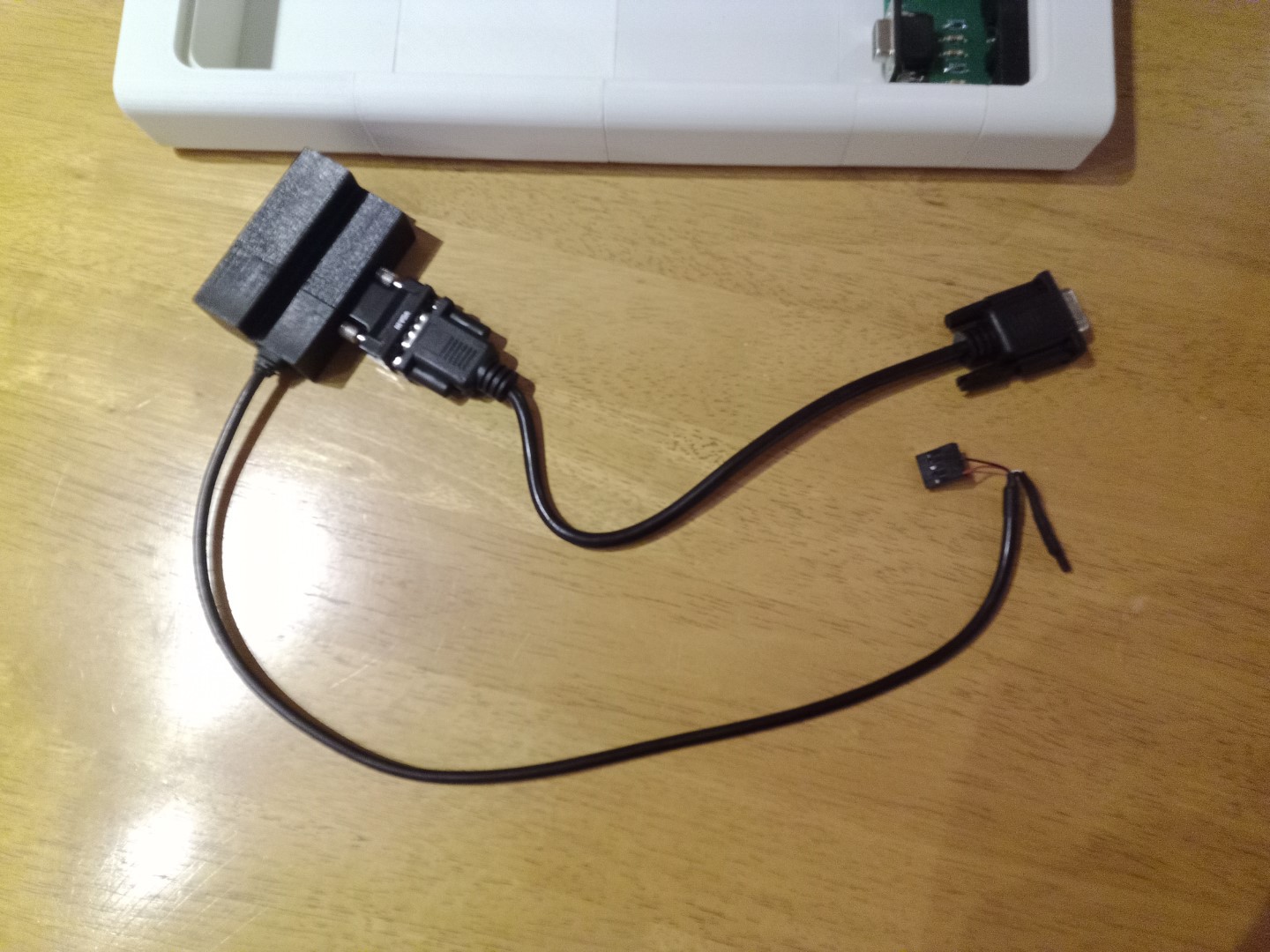
Either way, once we have a lead and an appropriate female header connector, we'll need to wire it correctly for the PicoMiteVGA PCB Header.
- Remove all of the wired pins from the female header plug. If you're not sure how to do this, look in the project logs for some guidance.
- Except for the RED wire and the BLACK wire, individually heatshrink or insulate with tape, the bare metal ends of the other wires.
- Now, heatshrink or tape all of the insulated ends together. Ensure that there are no bare wires or metal visible in the bundle.
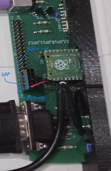
- The header that comes with the mini-USB lead suggested in the parts list, has a 10-pin header block. We need to put the RED and BLACK wired pins into the holes as shown in the two photos below, so that the RED wire goes to PIN 40 and the BLACK wire goes to PIN 38 of the PCB Header.
![]()
![]()
-
6Assembling the HDMI port
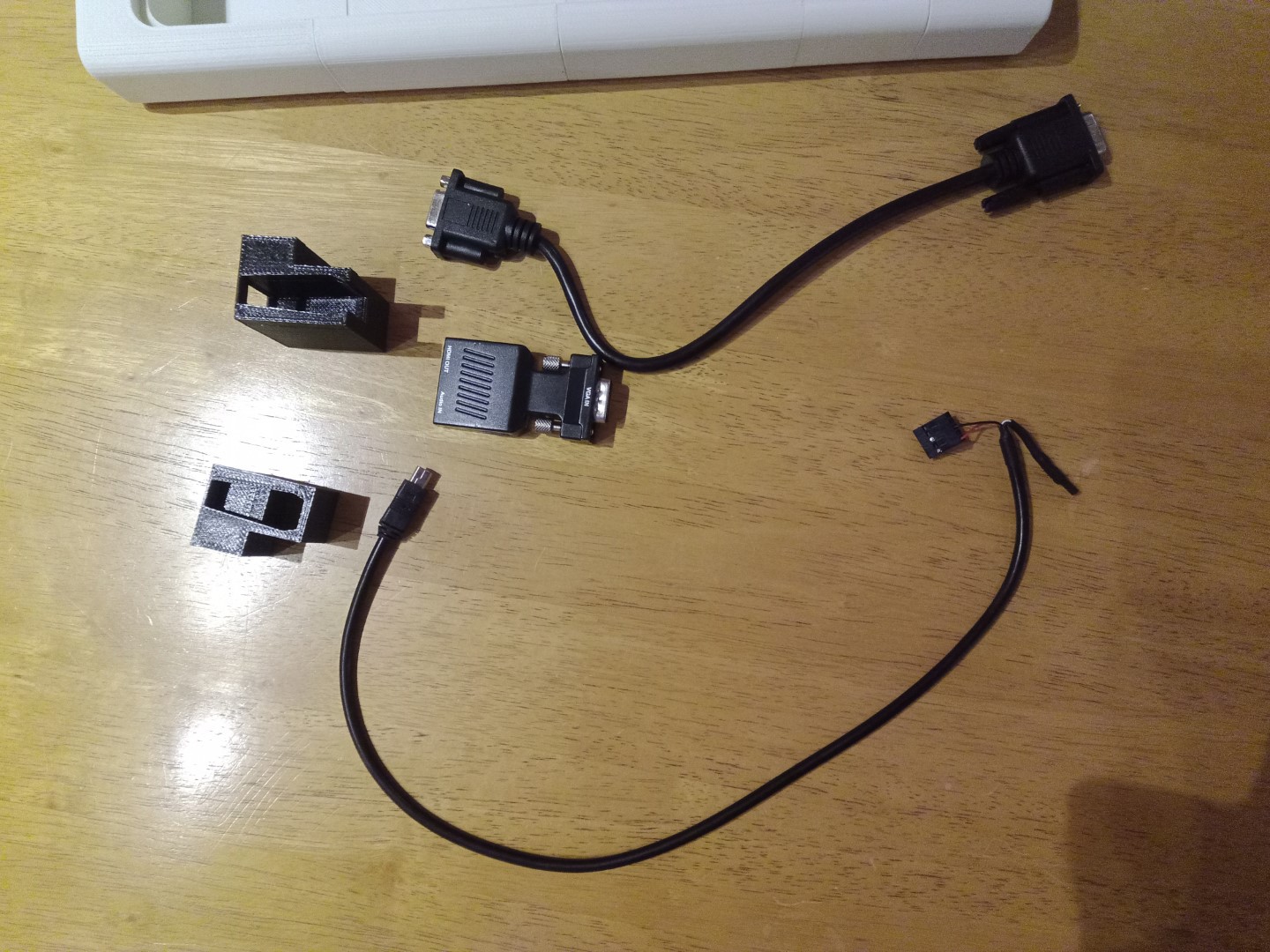
Now that we have our power cable ready, we should have the parts in the photo below:
![]()
Photo: Two 'halves' of the 3D printer holder, VGA to VGA cable, VGA-to-HDMI adapter and mini-USB to header cable.
- Insert the adapter into one piece of the holder and push the other piece tightly onto it, ensuring that you can access the HDMI connector fully afterwards.
- Connect the mini-USB plug to the adapter, through the hole in the side of the holder, ensuring that it is fully seated and secure.
- Plug the VGA cable into the VGA socket on the adapter and loosely tighten the locking screws.
Your assembly should now look like this:
![]()
-
7Assembling the PCB Holder
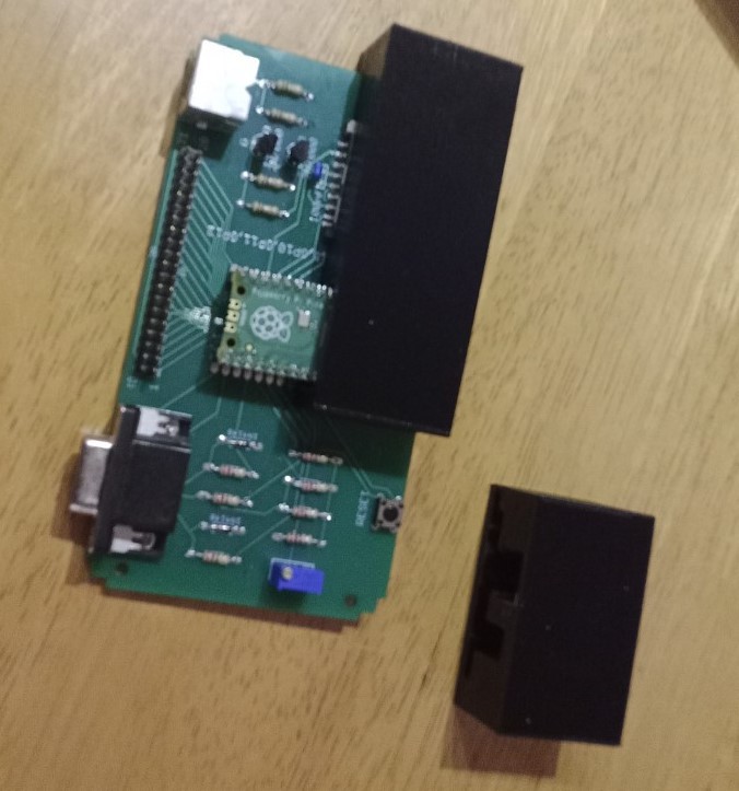
Now get your PicoMiteVGA board and the two 'halves' of the PCB holder, as in the photo below:
![]()
Starting with the larger piece of the PCB holder, GENTLY AND VERY CAREFULLY align and push the PCB into the shaped-slot.
Note any resistance or catching of components on top and component leads underneath.
Immediately, stop and pull the PCB back out. Turn over the PCB and trim away the lead that sticks out, ensuring that you do not damage the solder joint.
Repeat this process until the PCB slides in to fit snugly and slides out easily when required.
![]()
Next do the same again with the smaller piece of the PCB holder.
Watch out for the potentiometer (the blue thing with a brass screw in the photo above), it is relatively tall. You may need cut or file away a bit of plastic at the top of the slot for it.
![]()
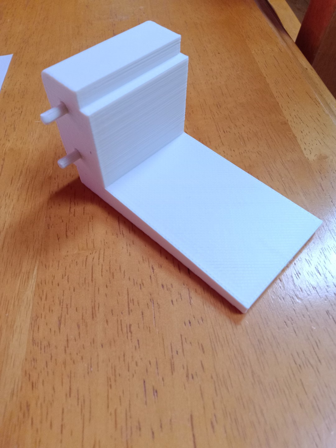
Remove the PCB, glue the two pieces of the holder together and allow to harden. Insert the PCB again and place the unit inside the case body as shown below:
![]()
Gently push the whole unit into the cutout for the PCB holder. Ensure that fits neatly and then push it back out from the outside. Apply a few drops of superglue to the inside of the case body, inside the cutout and push the PCB holder ONLY into the cutout and allow to harden. Insert the PCB when dry.
![]()
Next, insert the blanking plate into the rear port of the case, on the right. Do not glue this right now, as we might want to replace it later with other I/O connectors.
Put a few drops of glue in the cutout of the rear port on the left and insert the HDMI port unit, ensuring that it is the right way up (the thin part should be at the top).
Finally, connect up the cables for the keyboard, VGA and HDMI power, as in the phot below:
![]()
-
8Final checks and power on
Double and if necessary, triple check, the cabling and wires, especially the HDMI power connector header plug.
- is it definitely on the correct end of the PCB connector (see photos) ?
- is the RED wire definitely going to PIN 40 of the PCB connector?
- is the BLACK wire definitely going to PIN 38 of the PCB connector?
- are the unused wires definitely insulated from each other and out of the way of everything else?
- is the Raspberry Pi Pico definitely undamaged and seated securely, the right way around, in the PCB socket?
- is the keyboard cable correctly re-connected, if you shortened it yourself?
- is the keyboard plugged in and the P/S2 socket undamaged?
- Is the mini-USB power cable firmly connected to the HDMI adapter?
- is the VGA to VGA cable connected firmly?
- will any of the cables get trapped between the case and keyboard when they are joined together?
Fix any issues you see now, before we go any further.
Once all is good, connect a HDMI cable to the HDMI socket on the back of the case and to an HDMI monitor, then power on the monitor. Connect a micro-USB 5V power supply to the socket on the right-hand side of the case. You should see the following happen:
- All three BLUE LEDs on the keyboard will light up for a moment, then go out.
- A few seconds later, the keyboard CAPSLOCK LED will turn on.
- A second or two after that, the PicoMiteVGA boot up banner screen will display on your monitor.
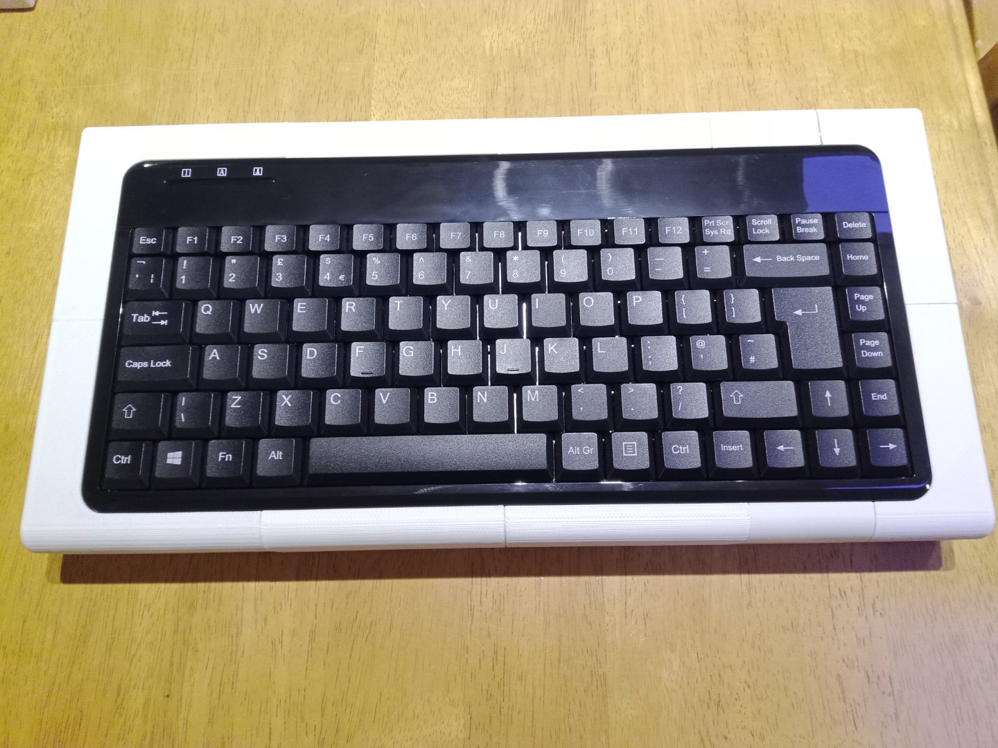
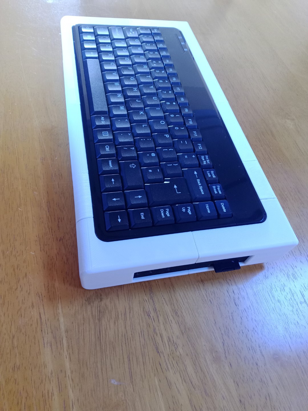
Now, clip the keyboard into the case. It should be a nice tight fit so that it stays in without fixings.
![]()
![]()
![]()
If you have no plans for adding sound or other stuff to your RETRO 1 Home Computer, the go ahead and glue the keyboard and blanking plate in place.
If you hope, like me to add sound and perhaps a RTC, etc. in a later project, then don't glue the keyboard or blanking plate in yet.
-
9Finishing touches
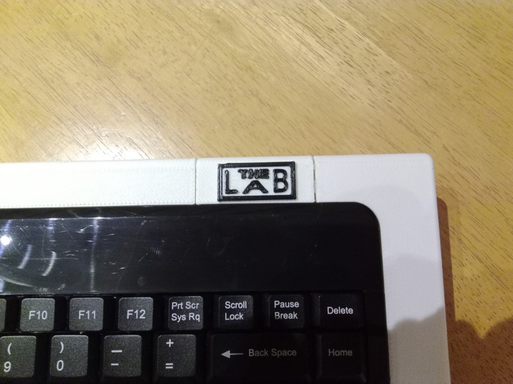
Although I didn't bother to sand or fill or paint any of the parts, I did feel they deserved a logo or two.
So I used the Microsoft 3D Builder program to load a set of characters that can be found by selecting "Letters and Numbers" in the "3D Library" window, when it starts up.
![]()
![]()
RETRO 1 - Home Computer Console
Modular, customisable, 3D printed, retro-style case for a home computer


Discussions
Become a Hackaday.io Member
Create an account to leave a comment. Already have an account? Log In.