Chris
Chris-
PVC Tube
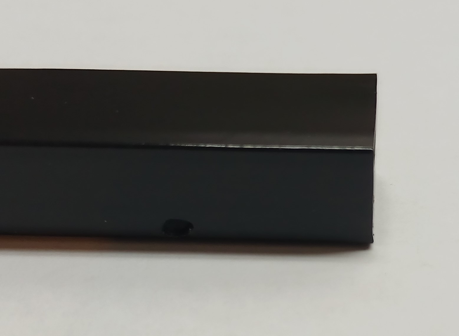
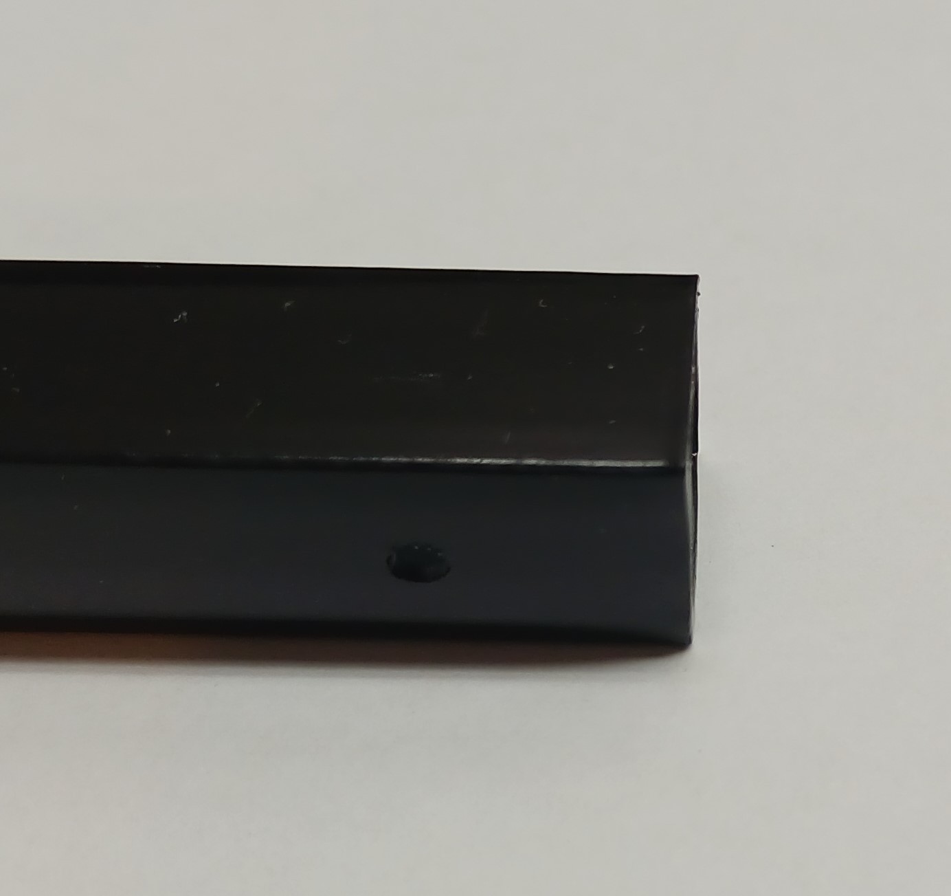
03/10/2024 at 00:46 • 0 commentsI cut the PVC tube to match the width of my keyboard (256mm), then drilled the following holes:
- 3mm hole in the center of the middle of what will be the top of the tube, for the two prongs on the bottom of the LED.
- Two 1.5mm holes 105mm from the right hand end of what will be the top of the tube, for the two prongs on the momentory button (I cut off the other two prongs).
- 2mm holes, 15mm in from each end and close to the bottom edge of what will be the front face (side facing keyboard), for the piezo sensor wires.
- 2mm hole in the rear side (away from the keyboard), for the PCB screw. Mark the correct position using a spare PCB.
I sprayed the tube with matt black enamel paint to match my keyboard. Some pictures:
![]()
![]()
![]()
-
JST SH Plug Wiring
03/09/2024 at 00:17 • 0 commentsFor this a bought an IWISS IWS-3220M crimping tool from Aliexpress as cheap alternative to the official crimper. Given the small size of the SH connector I recommend buying plenty of the SH contact (SSH-003T-P0.2-H), I bought 100 and got through a quarter of them before I had mastered the art of crimping. Instructions come with the tool and very detailed steps and pictures can be found in the official documentation from JST (CHM-1-2146).
My process was as follows:- Strip ~5mm of insulation from the 32AWG wire (smallest size compatible with SH contacts), then twist and cut the conductor to ~1.25mm.
- Close up the crimping tool so that a gap remains for insertion of the contact. From the back (side with no writing) insert the contact into the 1mm slot in the crimping tool. Make sure the front of the contact is aligned with the front of the tool. Insert the wire from the front, I used a finger nail about 1.25mm back from the conductor to control the insertion depth. Slowly completely close the tool.
- Check the crimp under a microscope to make sure it is consistent with the pictures in the JST guide.
- With a small pair of pliers very gently squeeze the two parts of the crimp, to make sure they are narrow enough to slide into the plug with only minimal resistence.
- Verify that the crimped contact can be inserted into the plug, without sliding it until it locks.
- Put the wires with attached connectors to one side, next step is to thread them through the square PVC tube.
-
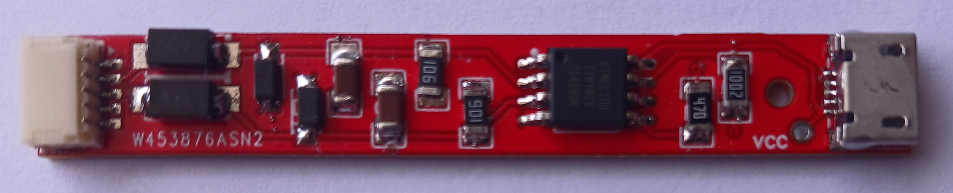
Complete PCB
03/03/2024 at 06:01 • 0 commentsHere is the completed PCB; I soldered all the components using solder paste and a soldering iron.
![]()
Next stage is to wire up the JST SH plug.
-
Assembly Improvements to PCB
03/02/2024 at 21:58 • 0 commentsI had a few problems assembling the PCB into the PVC tube, this was because I had not thought in detail about two things:
* how to solder on the wires, so that afterwards the PCB could be pushed into the tube.
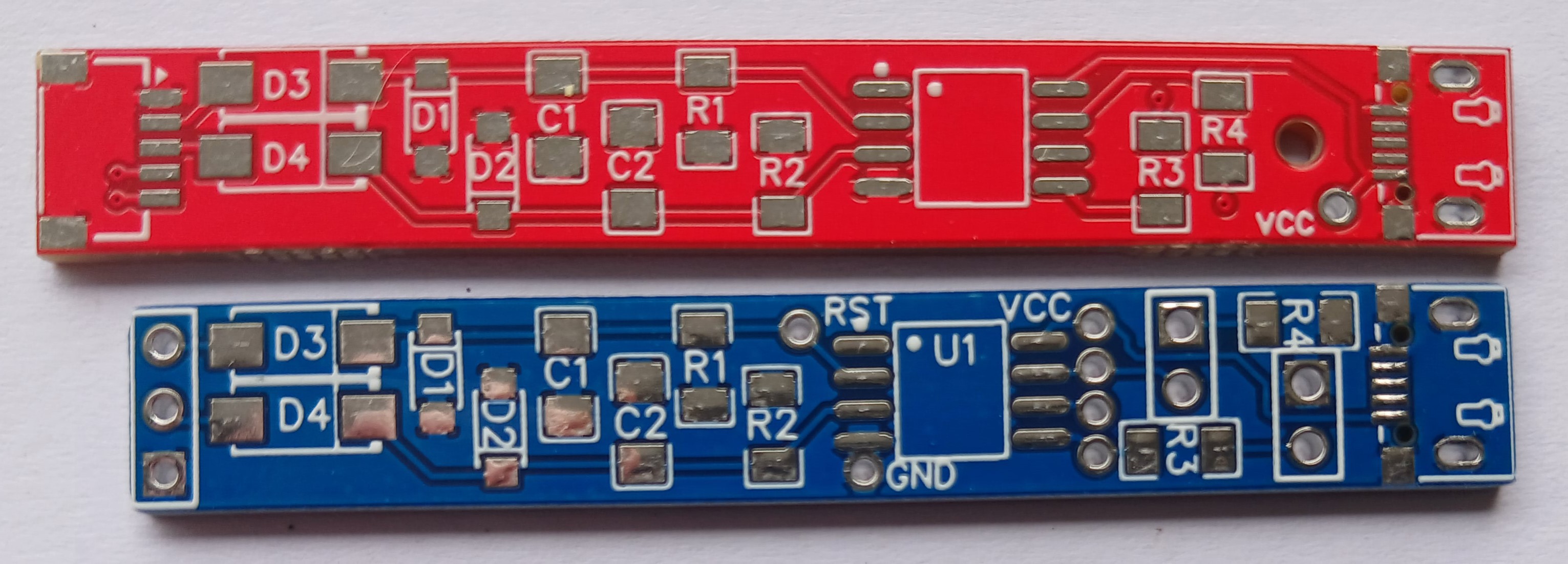
* how to secure the PCB in the tube.When I had an offer from PCBWay to sponsor another iteration I decide to do something about these issues by redesigning the PCB. I made two changes:
* Added a JST SH 5 way socket so I could plugin in a connector with all the wires.
* Added a hole in the PCB just behind the USB socket, so that I could use a small screw through the PVC tube to secure it.
I also removed the extra connection holes around the Attiny85 for programming, as the programming clip worked so well I never used these.I had not used PCBWay before, so it was interesting to try a new service. The online order page is well organised with help available under the ? for each specification item. I read the excellent capabilities page in conjuction with filling in the specification to make sure I understood what was possible and that these lined up with the settings in my PCB design tool.
For my simple PCB only three specification items needed to be changed from the default values:
* Size
* Quantity
* Colour
If you are just beginning with ordering a simple PCB this will almost certainly be the case for you too. Online chat is available if you do have questions.Once I went ahead with the order, the progress through the review, manufacturing and shipping process was clearly displayed and I received an email at each stage. Production took about 4 days and shipping with DHL ($20) took less than a week, so a very efficient service!
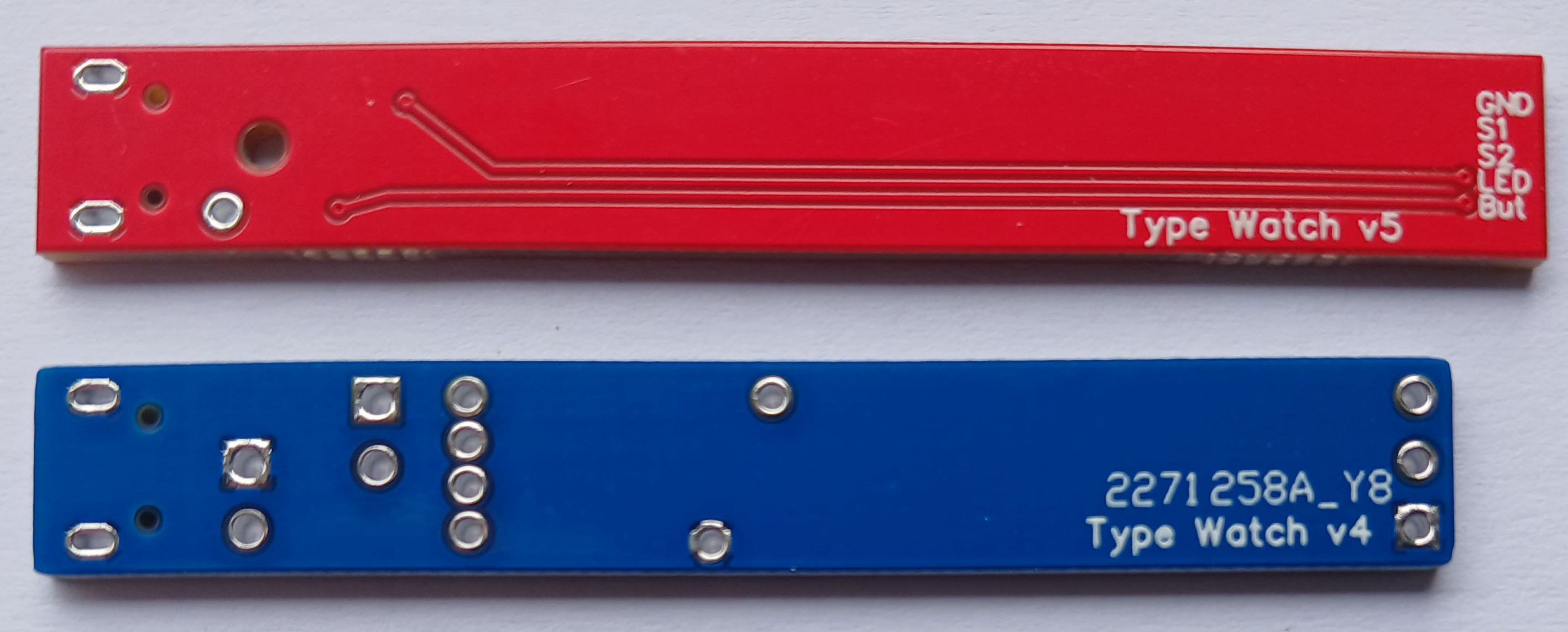
Both sides of the old (blue) and new (red) PCB versions are shown below.
![]()
![]()
On the back of the new PCB the labels for the connections are the minimum supported character height of 0.8mm, these are very clear and readable, something I have found not as good from other manufacturers.
Next step is to solder on the SMD components, I will report on this shortly.
Gentle Typing Trainer
Uses piezo sensors under your keyboard to sense harsh typing and warns you with the flash of a LED. Helps to guard against OOS.