Close
0%
0%

KS Zigbee Gateway

My own Zigbee Gateway with speaker output for realtime audio notifications, with MQTT support and more

Similar projects worth following
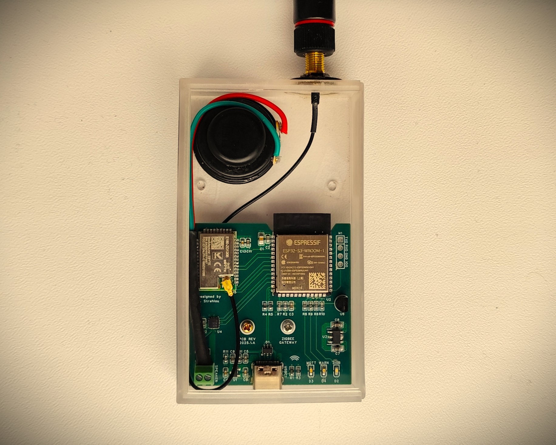
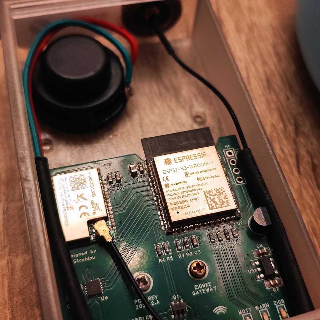
Zigbee Gateway based on EFR32MG1 (EBYTE E-180 module) and ESP32S3 (ESP32S3-WROOM-1) chips coupled with MAX98357A ((16 TQFN) for audio notifications.

MOTIVATION

When it comes to making own PCBs, there's always (along with that soldering smell) a little magic in the air... A lot of creativity ends up with a device which will be used to resolve a problem and make life easier.

In my old apartment I had basic power outlet setup controlled via a 433MHz radio controlled by ESP8266 (you can find it in my projects as Raesp Gateway).

However, as we're reaching another life milestones with my amazing wife ♥️, some inspiration grown in my head and I've challenged myself to build my own Zigbee Gateway.


BUT WHY JUST DON'T BUY A ZIGBEE USB STICK?

I would like to have full control over devices, control over the flow between Zigbee and the internet, and voice notifications in one device.


ROADMAP

First step known also as MVP is to create a device which works as serial-to-network agent (remote serial port) and is able to handle HomeAssistant built-in ZHA integration. The device should also support audio notifications and onboard temperature sensor. Zigbee Network should be validated by successfully pairing a Zigbee device into a network hosted on the gateway.


BOARD FEATURES

  • Wi-Fi and Bluetooth 5.0 connectivity
  • Full speed USB 2.0 to flash code and resources
  • Independent Zigbee 3.0 network processor
  • 3W output capable audio codec chip
  • Onboard digital temperature sensor
  • Various protection measures (overcurrent, short circuit, soft-start)
  • Easy to pair with Home Assistant (EZSP)

  • 1 × MAX98357A Audio ICs / Audio Amplifiers
  • 1 × ESP32S3-WROOM-1 System on chip with RF frontend
  • 1 × AP7361C Low dropout voltage regulators
  • 1 × AP2337SA Power Management ICs / Power Supply Support
  • 1 × DS18B20 Sensors / Temperature, Thermal

View all 6 components

  • Step 8: Latest cosmethic changes

    h4rdc0der13 hours ago 0 comments

    Think before pouring outer layers with ground. It is usually unnecessary for 4+ layer sandwiches.

    After conducting further research, I was able to remove the top layer ground pour and implement a few minor firmware improvements.

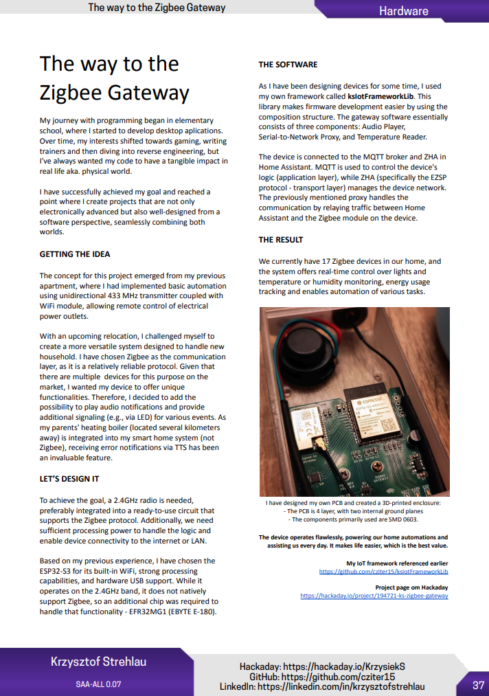
    Here's fresh PCB photo:

  • Step 7: It's stable, only minor changes!

    h4rdc0der11/28/2024 at 09:37 0 comments

    I recently revised the PCB design to enhance its structure and manufacturability:

    • The stackup was modified to position the ground planes centrally, ensuring optimal signal integrity.
    • The bottom layer was divided into two sections: 5V and 3.3V, each with its own dedicated ground plane for the signals.
    • Only two traces are routed on the bottom layer: one for the delay circuit (soft-start for the ESP32) and the other for activating the DAC circuit.
    • A ground plane was added to the top layer, which does not affect the electrical performance but simplifies the manufacturing process.
    • I also introduced a damper circuit to address potential issues related to the ferrite bead.
    • Component values were adjusted, and all schematics and Gerber files were updated accordingly.

    In terms of software, I implemented several changes, with a few key improvements as follows:

    • The jingles (welcome, alert, and info tones) were updated to be more pleasant to the ear.
    • The device no longer plays the welcome notification during app rotation (e.g., when WiFi reconnects after a router restart), which is particularly useful at night.
    • Fixed issues related to voice notification playback.
    • Introduced functionality to indicate active notifications via a blinking LED, controlled through MQTT in Home Assistant, based on the "persistent notification count."

    The previous PCB has been operating flawlessly so far, reliably controlling devices in the home. The new version performs just as well!

    Lastly, I’d like to share that the project was also featured in an article on Hackster. Thank you for discovering and mentioning it — it's incredibly motivating! Thank you, Gareth!

    If you want to read the article click here to read it on Hackster

  • Step 6: Enclosure

    h4rdc0der03/19/2024 at 14:25 0 comments

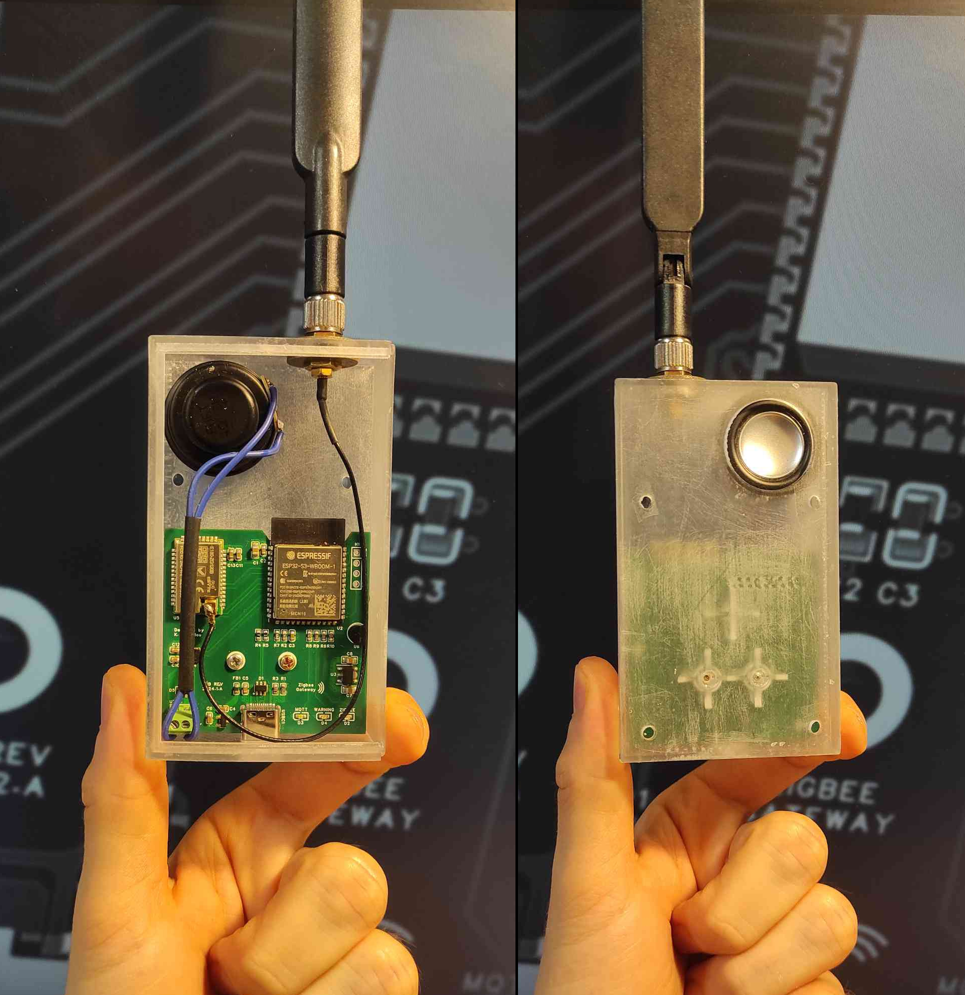
    The 3D-printed enclosure has recently arrived. Unfortunately, I made a mistake and the mounting holes are on the reverse side. 

    The housing consists of two parts. The larger part can be seen in the photo and the other part is the sliding cover. The printed circuit board is attached to the housing with two screws.

  • Step 5: Minor improvements

    h4rdc0der03/06/2024 at 22:42 0 comments

    There's still some work remaining in the firmware, before the device can be mounted on the wall.

    Some latest improvements include:

    • Implemented playlist support in Audio component. Now TTS can be mixed together with flash-hosted files. Example usage - alarm jingle followed by TTS audio description.
    • Implemented proper GPIO cleanup on Audio component destruction.
    • Implemented proper GPIO cleanup on Temp Sensor destruction.
    • General stability improvements, including audio decoding library updates.
    • Improvements in ksIotFrameworkLib targeting Device Portal (device info, input data types) and device config storage.

  • Step 4 - Code cleanup and more

    h4rdc0der02/22/2024 at 21:04 0 comments

    Recently I have been mainly involved in firmware development.

    I've introduced few smart tricks:

    • CPU is set to 240 MHz only when decoding audio stream and then goes back to 80 MHz when no more data is in the buffer.
    • New LED driving mode - using pullup/pulldown to significantly decrease the amount of emitted light.
    • Automatic baud rate detection, which means the device is able to talk at 57600 and 115200 and will doscover the speed automatically.

    I have also improved some things in the framework.

    The other thing I managed to achieve is OTA Zigbee Gateway Firmware update, which turned out to be simple to integrate into the Elelabs Flasher (added raw mode for flash and serial over LAN).

     Now the firmware update is really simple:

    1. The user starts the device portal.
    2. After logging in, zb-bootloader command is issues by the user on the terminal tab.
    3. The user starts python script to flash the .gbl file via xmodem protocol (uart over network)
    4. The module is restarted using zb-reboot terminal command.

    I have also managed to properly setup MFG tokens, so the device is properly displayed on HA subpage.

  • Step 3 - Running up the stack

    h4rdc0der02/09/2024 at 15:45 0 comments

    Looks like I'm on a good streak!

    After many hours of debugging all the stuff, I managed to fix audio issue in external library (https://github.com/schreibfaul1/ESP32-audioI2S/issues/626). Now the audio startup noise is gone.

    I've also ordered smart bulb, which paired flawlessly. Check this out!

  • Step 2 - Forming it all up

    h4rdc0der02/08/2024 at 22:35 0 comments

    The application skeleton for ESP32 (main CPU) was built on my ksIotFrameworkLib, which provides some fancy stuff like device configuration portal, MQTT support, LED management etc.

    Then the E-180 module has been studied in relation to firmware update. The idea was to use ESP32S3 as a proxy to flash the module. It was challenging since there are a plethora of possible solutions.

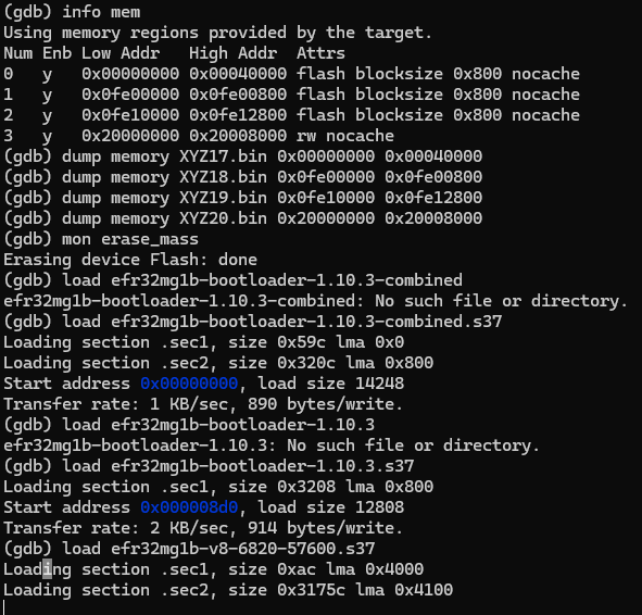
    After some trial and error, the module was flashed with the help of esp32-blackmagic, which supports the SWD protocol in addition to being primarily used for remote on-chip debugging. It was necessary to change settings to match PCB design IO numbers for SWD IO and CLK lines.

    Here's the link for EFR32 firmware blobs:
    https://github.com/cziter15/EZSP-Firmware

  • Step 1 - Solder and verify

    h4rdc0der02/08/2024 at 21:42 0 comments

    The board has been assembled to test the circuit's functionality. Zigbee module was mounted on the board right after DAC verification.

    The most challenging part was soldering the DAC chip and then, a bit easier was USB-C soldering.

    Quick examination confirmed correct voltage generation, DAC functioning, but noise during playback startup.

    Here's a little demo:

View all 8 project logs

Enjoy this project?

Share

Discussions

Similar Projects

Does this project spark your interest?

Become a member to follow this project and never miss any updates