Close
0%
0%

DPS201: Lab PSU

Ultra small lab power supply with digital control.

Similar projects worth following
DPS201 is a software controlled lab power supply designed for hobbyists and students. It features a single output channel which is programmable from 0V to 20V in 100mV steps. It also sports a current limiting feature which can be programmed from 0A to 1A in 10mA steps. The aim of the project is to reuse an existing wall adapter together with the DPS201 to act as a simple lab supply. The supply is controlled and monitored by a PC through a USB link or using on board controls. The software as well as the hardware is still under development.

Overview

The DPS201 is a PC controlled 0V to 20V and 0A to 1A lab power supply. The entire project consists of the hardware (the DPS201 it self) together with firmware and the PC software PScontroller.

Specs

  • Input voltage
    9 - 25VDC
  • Output
    0 - 20VDC (max output voltage decreases with input voltage)
    0 - 1A
  • Load regulation
    Constant Voltage: Less than 10%
    Less than 250uS recovery time for load change of half the rated output current at any constant voltage setting.
  • Line regulation
    Constant Voltage: Less than 0.01%
    Constant Current: Less than 2%
  • Ripple and noise
    Constant Voltage: Less than 10mV(RMS)
    Constant Current: Less than 10mA(RMS)
  • Programming resolution
    Constant Voltage: 100mV
    Constant Current: 10mA
  • Metering resolution
    Constant Voltage: 100mV
    Constant Current: 10mA
  • Programming accuracy
    Constant Voltage: 1%
    Constant Current: 1%
  • Metering accuracy
    Constant Voltage: 1%
    Constant Current: 1%

History

The DPS201 power supply is a product of weekend tinkering after reading one of late Jim William's excellent app notes, titled High Efficiency Linear Regulators. There he explains how one can design a ultra low dropout regulator using low R_DS(on) N-channel MOSFET and a switching pre-regulator which ensures the low dropout. Our design is based on exactly this principle, using LM2596 switching regulator as pre-regulator and a simple LM324-based linear regulator. This is a very stable configuration and the efficiency is high so that no heat sink is required. A lack of heat sink is essential to make the power supply small and cheap.

Theory of operation: hardware

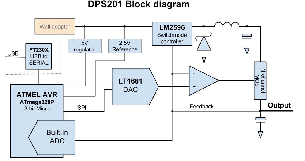
A simplified block diagram is displayed below. Note that the block diagram only shows the voltage feedback loop, a current feedback loop is of course also present in the circuit.

The voltage control and current limiting is handled by OPamps. In this case a pair of LM324 together with a precision reference (TL431) and precision resistors where needed.

The PC interface and control of the supply is fairly simple, the Atmel ATmega328P, a 8-bit micro controller, handles all logic. The interface to the analog circuitry is via LTC1661, a 10-Bit A-to-D converter which feeds the set voltage directly into the error amplifiers. The micro has a built in 10-bit D-to-A converter which is used to measure the output voltage and current. The USB signal from the PC is fed through FT230X, a USB to serial converter, which is opto-isolated from the main circuitry. Note that galvanic isolation is crucial for proper lab supply and even though our design is simple and essentially targeted at hobbyists, it is still much more useful to have a supply that is entirely isolated from earth. In our case, galvanic isolation is ensured by the AC to DC wall adapter that supplies the power to the supply and the optocouplers that electrically isolate the PC ground from the DPS201 signal ground.

One key goal of the project was to make the PSU as small as possible. This meant using SSOP and 0805 surface mount packages. Heat dissipation is very important in a small designs so the switch mode converter had to be efficient, especially at large loads. We managed to bring the PCB size down to 8 x 8 cm where most space is taken up by connectors. We decided to use proper banana jacks for output connectors to ease the use of the supply.

Theory of operation: software

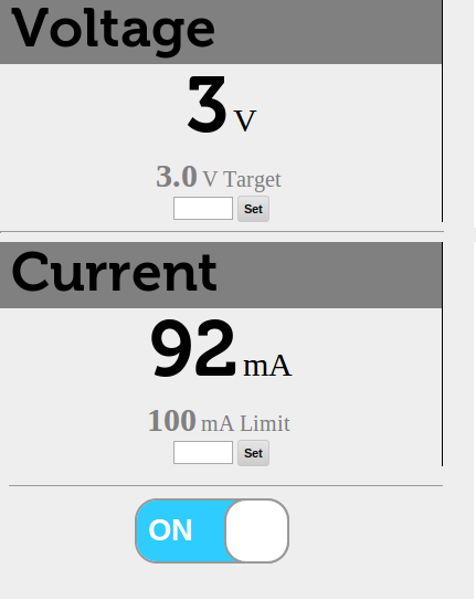
The DPS201 is controlled by a local python based web server. The web server connects to the DPS201 via USB and exposes it's functionality through an API.

A simple browser UI is provided (seen above) while more complex tasks can be performed by directly calling the API. The web server runs on Linux, Mac and Windows.
  • 1 × 78L05 Power Management ICs / Linear Voltage Regulators and LDOs
  • 1 × TL431BQ Power Management ICs / Voltage References
  • 1 × LTC1661CMS8 Data Converters / Digital to Analog Converters (DACs)
  • 1 × FT230X Microprocessors, Microcontrollers, DSPs / Microprocessors (MPUs)
  • 2 × CNY17F-2XSM Opto and Fiber Optic Semiconductors and ICs / Optocouplers and Optoisolators

View all 11 components

  • Todos

    Fridrik08/20/2014 at 00:19 1 comment

    I am just about to finish uploading a short video which demos the DPS201 in action, actually to use the phrase in action is a gross overstatement. I merely turned the output on while recording. In any case, over the past few days I've seen some issues that need to be addressed in coming weeks:

    • The analog circuitry must be analysed with respect to stability. Current mode buck converters are generically unstable with uncompensated error amplifiers. this leads to all sorts of problems. In this case I'm seeing oscillations of the output and in the most severe cases noise being spewed out that affects the USART communication.
    • The opamps (TL072) have some offset error which must be calibrated out in firmware.
    • The software needs to be slightly more robust when plugging and unplugging the device.

    Hopefully we can manage to solve these quickly.

  • Hardware source files

    Fridrik08/19/2014 at 00:18 0 comments

    You can now find the hardware source files, gerbers and pdf of the schematic on github (link on left). I used the open source PCB design softwared gEDA for all design so anyone should be able to load up the source files and modify them.

  • Successful control via USB

    Fridrik08/13/2014 at 21:29 0 comments

    After finishing soldering the rest of the board, the next task was to modify the already quite complete firmware to work with the new board. This was rather simple, the main issue was getting the USART communication working properly, since the new micro (AtTiny167) uses LIN/USART protocol while the micro we have been using until now (Atmega328P) just uses a simple USART. 

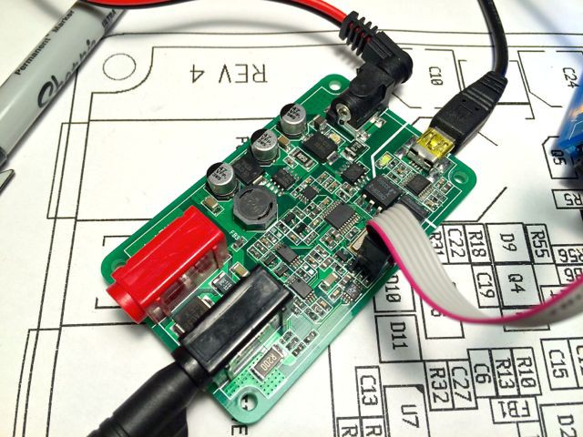
    Here you can see the board being flashed for the first time!

    Last few nights I have been messing with the firmware to get everything working properly, and I believe we are very close now. Last night I was able to get first communication over USB and finally tonight I was able to use the software to send proper commands to the PSU. That is I am able to program the voltage and read the measured voltage back. In principle I can also program the current limiting but I had to temporarily disable the current reading. Unfortunately. I fell in the trap of connecting the current reading net to an IO pin of the AtTiny that also serves as the SPI slave-select pin. This is bad because when the SS pin is pulled low while the AtTiny acts as a SPI master, it quickly drops out of master mode and acts as a SPI slave. This is unwanted because we need the micro to act as a SPI master always to control the DAC which is an SPI device. For now I simply disabled the current measurement feature. I will bodge a connection to a different pin on the micro in coming days.

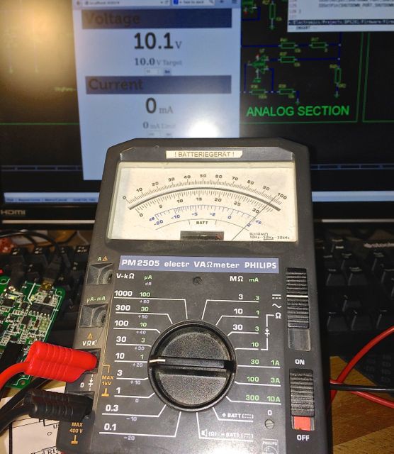
    Here is the success moment caught on camera, where in the background you can see that the PC software is set to 10V, and it reads back 10.1V from the DPS201. On the multimeter in front you can see the measurement essentially being confirmed (at least up to calibration errors.)

    The next task is to connect loads to the supply and characterise it properly.

  • PCB's arrived

    Fridrik08/04/2014 at 22:33 0 comments

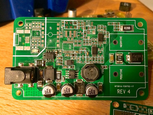
    PCB's arrived today from the board house.

    As you can see, this board is just half-assembled. I want to make some tests before I continue. Mainly to make sure that the switch mode converter runs smoothly with the input filter in place and to ensure that the efficiency is good enough to avoid thermal issues. The board is surprisingly small in the hand, our earlier prototype was 10 x 8cm, which feels quite bulky. The new version is only 5 x 8cm, half the area of the old board.

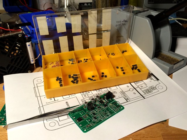
    Since there was almost no space on the board for component designators, I printed out a large reference diagram to work with when assembling. It worked out nicely.

View all 4 project logs

Enjoy this project?

Share

Discussions

Similar Projects

Does this project spark your interest?

Become a member to follow this project and never miss any updates