-
Todos
08/20/2014 at 00:19 • 1 commentI am just about to finish uploading a short video which demos the DPS201 in action, actually to use the phrase in action is a gross overstatement. I merely turned the output on while recording. In any case, over the past few days I've seen some issues that need to be addressed in coming weeks:
- The analog circuitry must be analysed with respect to stability. Current mode buck converters are generically unstable with uncompensated error amplifiers. this leads to all sorts of problems. In this case I'm seeing oscillations of the output and in the most severe cases noise being spewed out that affects the USART communication.
- The opamps (TL072) have some offset error which must be calibrated out in firmware.
- The software needs to be slightly more robust when plugging and unplugging the device.
Hopefully we can manage to solve these quickly.
-
Hardware source files
08/19/2014 at 00:18 • 0 commentsYou can now find the hardware source files, gerbers and pdf of the schematic on github (link on left). I used the open source PCB design softwared gEDA for all design so anyone should be able to load up the source files and modify them.
-
Successful control via USB
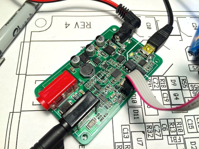
08/13/2014 at 21:29 • 0 commentsAfter finishing soldering the rest of the board, the next task was to modify the already quite complete firmware to work with the new board. This was rather simple, the main issue was getting the USART communication working properly, since the new micro (AtTiny167) uses LIN/USART protocol while the micro we have been using until now (Atmega328P) just uses a simple USART.
![]()
Here you can see the board being flashed for the first time!
Last few nights I have been messing with the firmware to get everything working properly, and I believe we are very close now. Last night I was able to get first communication over USB and finally tonight I was able to use the software to send proper commands to the PSU. That is I am able to program the voltage and read the measured voltage back. In principle I can also program the current limiting but I had to temporarily disable the current reading. Unfortunately. I fell in the trap of connecting the current reading net to an IO pin of the AtTiny that also serves as the SPI slave-select pin. This is bad because when the SS pin is pulled low while the AtTiny acts as a SPI master, it quickly drops out of master mode and acts as a SPI slave. This is unwanted because we need the micro to act as a SPI master always to control the DAC which is an SPI device. For now I simply disabled the current measurement feature. I will bodge a connection to a different pin on the micro in coming days.
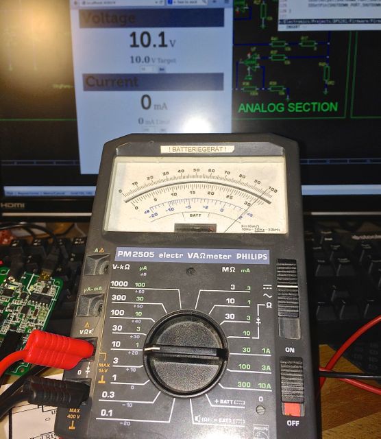
Here is the success moment caught on camera, where in the background you can see that the PC software is set to 10V, and it reads back 10.1V from the DPS201. On the multimeter in front you can see the measurement essentially being confirmed (at least up to calibration errors.)
![]()
The next task is to connect loads to the supply and characterise it properly.
-
PCB's arrived
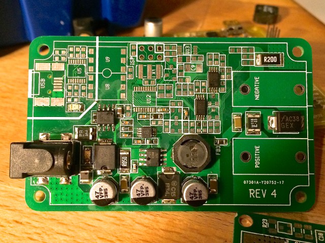
08/04/2014 at 22:33 • 0 commentsPCB's arrived today from the board house.
![]()
As you can see, this board is just half-assembled. I want to make some tests before I continue. Mainly to make sure that the switch mode converter runs smoothly with the input filter in place and to ensure that the efficiency is good enough to avoid thermal issues. The board is surprisingly small in the hand, our earlier prototype was 10 x 8cm, which feels quite bulky. The new version is only 5 x 8cm, half the area of the old board.
![]()
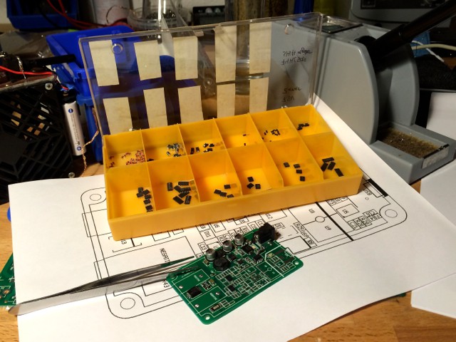
Since there was almost no space on the board for component designators, I printed out a large reference diagram to work with when assembling. It worked out nicely.