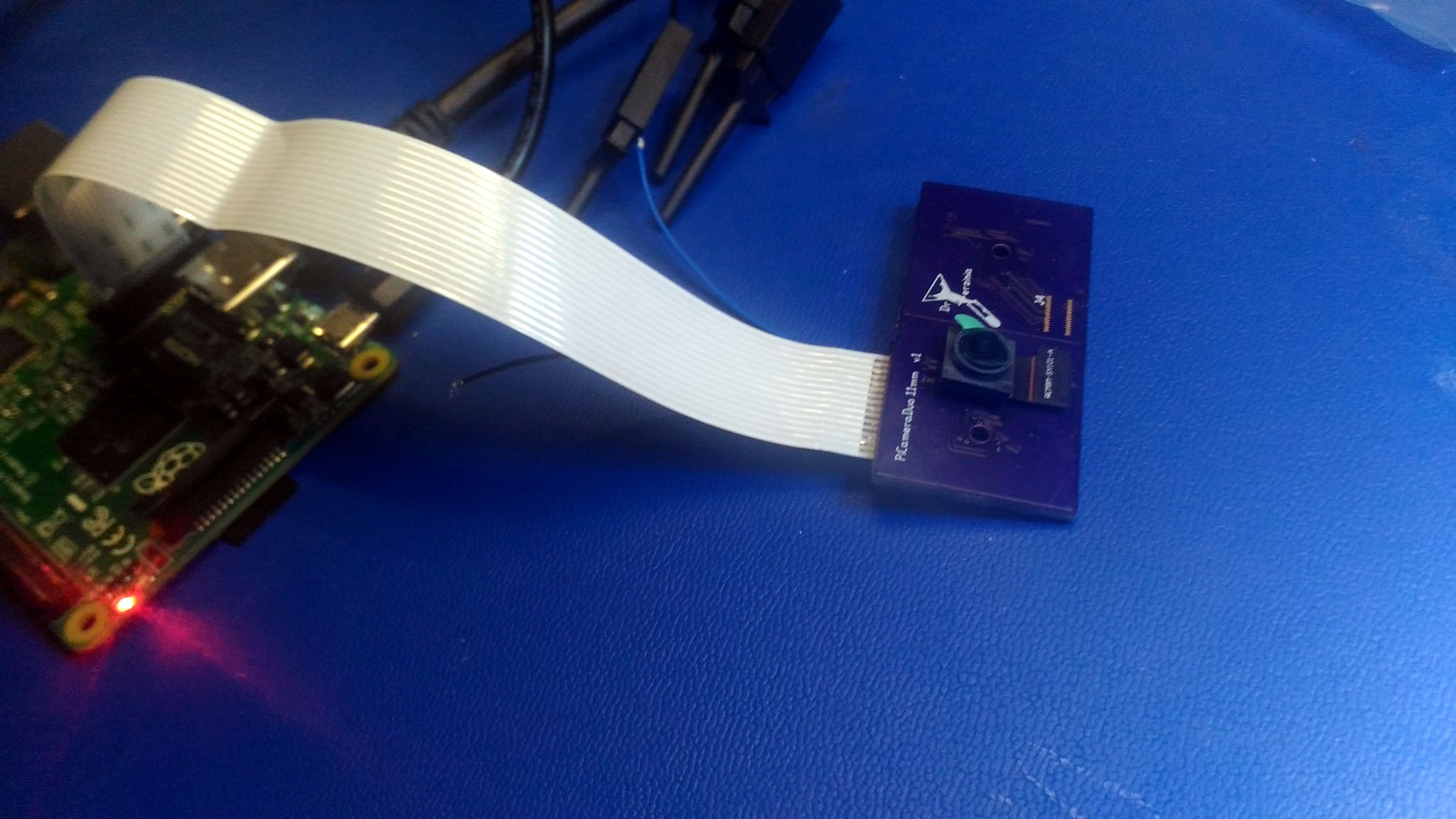
As it stands I have drawn up a full schematic for the board. I still need to measure the values of the capacitors and inductors but the basic functionality is apparent. There are 3 regulators, 2 LDOs that supply 2.8v and 1.8v and a buck that supplies 1.2v. There is a dual NMOS package that does I2C level conversion from the PIs 3.3v to the 1.8v for the sensor. There is also a 24MHz crystal to drive the clock of the sensor. There is an EVIL I2C cryoto chip used to lock down the Raspberry PI Camera driver so it wont work with cloned boards. Also there are common mode chokes on the differential data pairs.
Raspberry Pi Camera v2.1 Reversed
Reversed schematic and PCB of Raspberry Pi Camera v2.1
 DrYerzinia




 Raymond
 Monstrofil
 jcamdr70
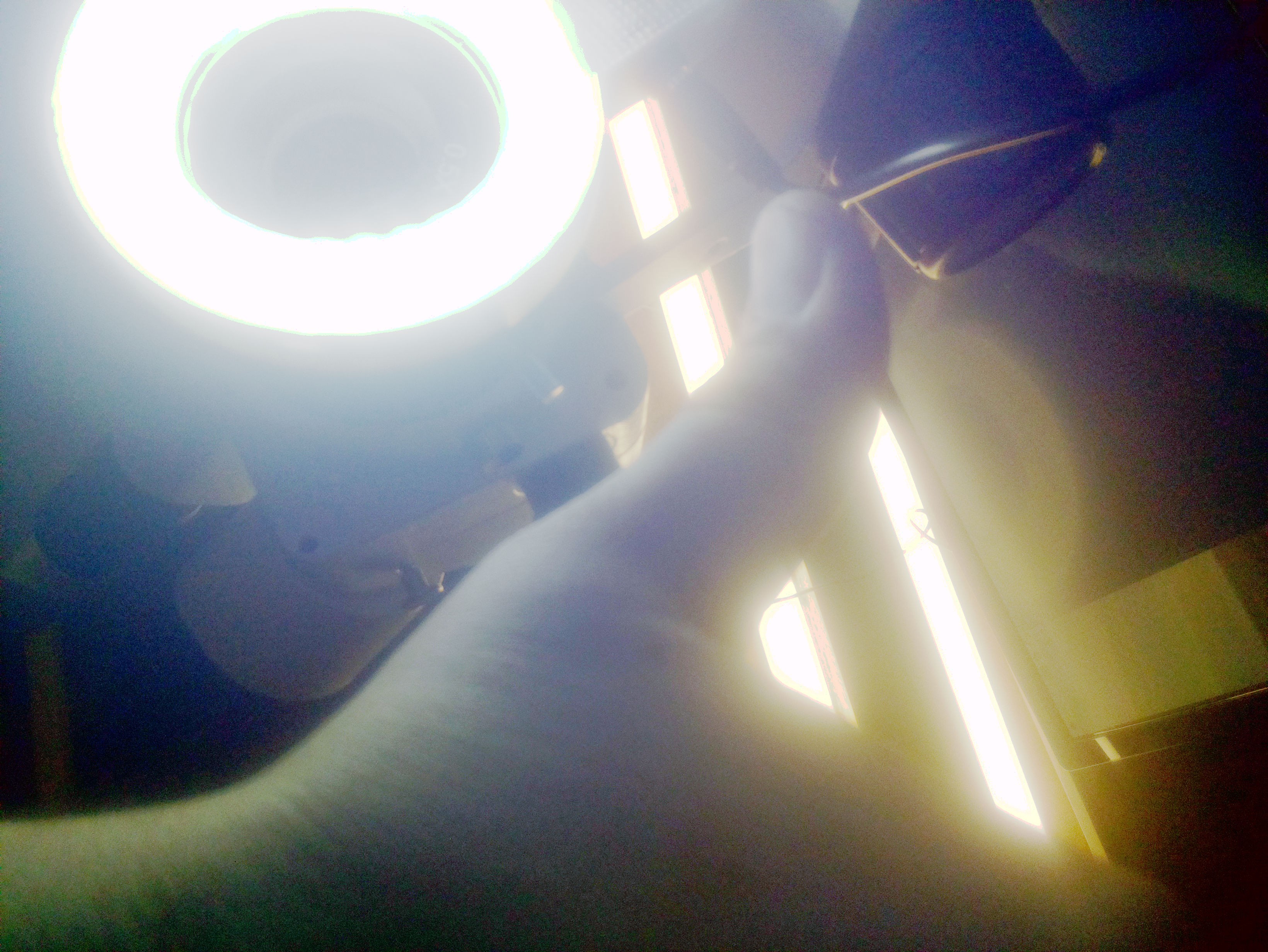
Sir I am getting vertical coloured lines only. I even tried a different connector and another raspberry Pi but getting same result. It was running fine and suddenly once I pulled out from its case and reconnected this happened. Whether the camera module is damaged?