Close
0%
0%

X65-SBC

Single-Board Computer based on 65C02 or 65C816 CPU with 2MB RAM, VGA graphics output, PS/2 ports, and high-quality sound.

Similar projects worth following
The X65 is an ultimate computer for everyone interested in the venerable 65-series of 8-bit and 16-bit CPUs, i.e. the 6502 and 65816. Specifically, it is built with the W65C02S or W65C816S CPU chips from Western Design Centre. The 16-bit 65816 (W65C816S) variant is the default and preferred CPU; all screen-shots and demos shown below were done on the 16-bit system.

The design is fully open-source and open-hardware, and we also prefer to use just the open-source development tools whenever possible. The X65 computer hardware is designed with modern electronics parts, but with a little bit of retro feel.The computer is backward compatible with the 8-bit Commander X16 -- i.e. it can run their ROM, but since that ROM is copyrighted
and non-free, this is a no-go in the long run. The goal is to build a fully *open* 8/16-bit system with good architecture and retro-gaming performance.

General Project Features:

* The CPU is W65C02 (8-bit) or the W65C816 (16-bit; default-preferred). The PCB supports both assembly options.
* Backward software compatibility with the Commander X16 computer. Can run unmodified CX16 ROM for testing purposes (beware: the CX16 ROMs are copyrighted non-free code!).
* Designed with components (chips) that are in production and available from normal electronics parts distributors in 2024, such as Mouser, Farnell, Digikey etc. We avoid obsolete parts.
* Balanced modern/retro design built around the central 65xx CPU supported by semi-ASICs (FPGAs) for system control (NORA), video (VERA) and audio (AURA) generation. The FPGAs are the little ones from the iCE40 series, and coded in verilog. These are modern takes on the "old masters'" designs with ULA, VIA, SID etc. There is no hidden ARM or RISC-V doing heavy lifting in the background.
* Free and open-source design. DIY and hobby-builders friendly. Low-cost to build even in small quantities by individual hackers.

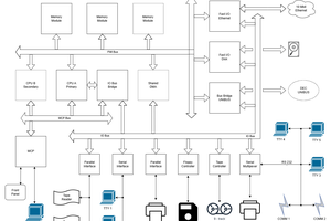
Block Diagram:
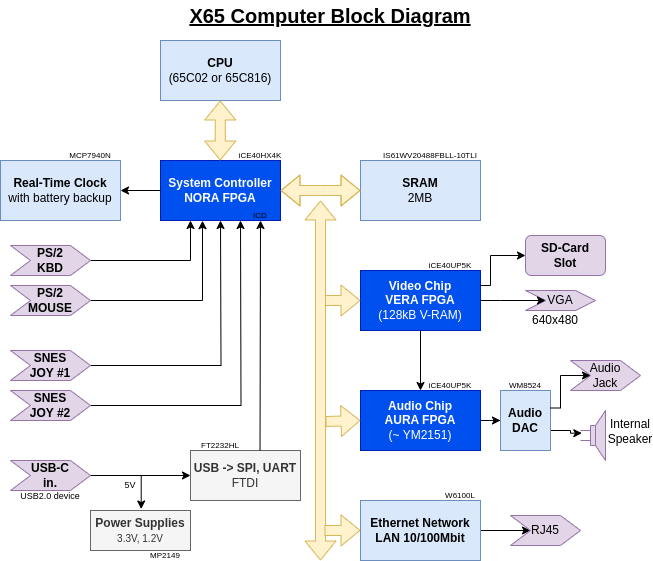
Hardware Specification:


* CPU: W65C02 or W65C816 in the QFP-44 package, running at 8MHz, supplied by 3.3V.
* Memory: 2MB asynchronous SRAM, common for ROM and RAM.
* System controller semi-ASIC, aka north-bridge, aka NORA: Lattice FPGA iCE40HX4K (TQFP-144) handles address decoding, glue logic, PS/2 interfaces, in-circuit debugger and more. "NORA" stands for NORth Adapter, has a similar function like the north bridge in a PC/X86 architecture. NORA takes care of the memory address map and hosts most of the IO registers.
* Two ports for **SNES-style controllers**, handled by NORA.
* Two **PS/2 ports for keyboard and mouse, handled by NORA.
* Colour video output through VGA connector, up to 640x480 pixels. Generated by VERA FPGA: the Video Embedded Retro Adapter, in Lattice FPGA iCE40UP5K. The same is used in Commander X16.
* Stereo audio output through 3.5mm jack port. Sound comes from two sources: FM-synthesis (OPM) by YM2151 clone IKAOPM implemented in AURA FPGA (iCE40UP5K), and Programmable Sound Generator (PSG) available in VERA FPGA. These are digitally mixed in AURA and passed to a DAC. Besides the output jack connector, the sound can be also heard from a small on-board mono speaker.
* SD-card slot supporting SDHC cards (handled by VERA FPGA).
* LAN 10/100Mbps Ethernet port (RJ45) implemented by Wiznet W6100 chip, with hardware-integrated TCP/IP v4/v6 stack.
* Real-time clock (RTC) chip with battery backup.
* In-circuit debugger (ICD) integrated with NORA and accessible over the device USB-C port from a host PC running Linux or Windows. The ICD can write all permanent (SPI-Flash) memories in the system, even in a totally empty / bricked state. PC host software is written in Python and should be portable to other fruitful systems besides Linux and Windows. Together with NORA the ICD supports JTAG-like functions like memory poke/dump, CPU stop/step, instruction trace buffer, interrupt forcing/blocking etc.
* Power input 5V from a standard USB Type-C device port. The X65 computer can be powered from a  host-PC USB port (for development with ICD), or runs standalone from a common Mains/USB phone charger with just 5V output.
* Single-board PCB 180x100mm, 4-layers.

Do you want to know more?

Find all project data - schematics, kicad projects, FPGA verilog code, documentation - in the github project repository https://github.com/jsyk/x65.

x65-sbc-revB1.pdf

Schematic X65-SBC rev.B1

Adobe Portable Document Format - 4.85 MB - 02/17/2024 at 21:33

Preview

  • Dreamtracker’s Rabbit Hole

    Jara10/26/2024 at 13:26 0 comments

    As mentioned in previous postMatej asked me if Dreamtracker app is running on X65. I told him that yes, it should run, but better to test it first myself. I downloaded Dreamtracker in its current version V0.71, fired it up, and well, after a promising start – I could see its main menu for a split second – the program crashed into the Monitor…. Well, that felt embarrasing 😮

    This youtube video shows the crashed start:


    The Monitor screen indicates the crash was caused by executing a BRK instruction. In 6502 CPU the BRK instruction has the opcode $00, and the value is typically used as a filler byte in empty regions. The PC=0xFEAC and RO=0x00 indicates the instruction was executed at a location near the end of the first ROM bank.

    I wanted to see exactly from where the CPU came to this instruction address. I don’t know how to do that on a regular 6502-based system, but on my X65 it was not so difficult. NORA FPGA already has a built-in In-Circuit Debugger (ICD). The ICD monitors instruction stream executed by the CPU in real time and stores instruction trace in a 512-element ring buffer, which could be read out to a PC over the USB link any time. NORA can also send ABORT signal the CPU when specific conditions in the instruction stream are encountered. Therefore, all I needed was to (temporarily) modify ICD in the FPGA to stop the CPU clock when the BRK opcode (0x00) is executed. This was done and these are the last seven instructions before the faulting BRK opcode:

    Cyc #  -25:  MAH: 0 (low :  0)  CBA: 0  CA: 3c3  CD:68  ctr:1f:----  sta:7f:r--emxPDS     PLA
    Cyc #  -21:  MAH: 0 (low :  0)  CBA: 0  CA: 3c4  CD:85  ctr:1f:----  sta:7f:r--emxPDS     STA $01
    Cyc #  -18:  MAH: 0 (low :  0)  CBA: 0  CA: 3c6  CD:68  ctr:1f:----  sta:7f:r--emxPDS     PLA
    Cyc #  -14:  MAH: 0 (low :  0)  CBA: 0  CA: 3c7  CD:40  ctr:1f:----  sta:7f:r--emxPDS     RTI
    Cyc #   -8:  MAH: 1 (low :  1)  CBA: 0  CA:372c  CD:a9  ctr:1f:----  sta:7f:r--emxPDS     LDA #$08
    Cyc #   -6:  MAH: 1 (low :  1)  CBA: 0  CA:372e  CD:20  ctr:1f:----  sta:7f:r--emxPDS     JSR $feab
    Cyc #    0:  MAH:41 (RomB:  0)  CBA: 0  CA:feab  CD: 0  ctr:1f:----  sta:7f:r--emxPDS     BRK #$00

    Let’s have a look at the instructions. The first four must be a part of an interrupt handler which ends with RTI, Return From Interrupt. Then we have “LDA #$08” which loads the value 0x08 into Acumulator register and “JSR $feab” a Jump to Subroutine at the address 0xFEAB. At this address the processor encounters the BRK instruction and NORA has stopped it. It really looks that the jump to $FEAB in ROM is intentional in the Dreamtracker code. So I searched the Dreamtracker code source and I found it pretty quickly: in the file x16.inc there are the following definitions of jump addresses:

        ...
        SCREEN_SET_MODE        := $FF5F
        SCREEN_SET_CHARSET        := $FF62
        screen_set_charset          := $FF62
        extapi            := $FEAB    <=== HERE
        i2c_write_byte        := $FEC9
        I2C_WRITE_BYTE        := $FEC9
        entropy_get            := $FECF
        ....

    Evidently $FEAB is supposed to be extapi in the ROM. We can find several references to extapi throughout the dreamtracker code, for example here in the main:

        ; Check for input from the keyboard, and do something if
        ; a key was pressed (return value is something other than 0)
    check_keyboard:        
        ;sei        
        ; call ps2data_fetch        
        lda #$08        
        jsr extapi              <=== HERE        
        jsr SCNKEY        
        jsr GETIN  ;keyboard        
        beq main_application_loop        
        sta zp_KEY_PRESSED

    I searched extapi in my copy of X16 ROM sources, and found none. Then I searched for $FEAB and found it in vectors.s:

        ; *** this is space for new X16 KERNAL vectors ***    
        ;    ; !!! DO NOT RELY ON THEIR ADDRESSES JUST YET !!!    
        ;
                .byte 0,0,0                    ; $FEA8
                .byte 0,0,0                    ; $FEAB      <=== HERE :-(
        ...
    Read more »

  • The X65 Saga Continues

    Jara10/03/2024 at 18:34 0 comments

    It's Autumn again and I am revisiting my Project X65. My list of to-do tasks is endless and growing still :-)

    * finishing tests of the A1 prototype
    * load BOM to Mouser
    * testing the USB interface
    * better ESD concept
    * indication of stopped CPU
    * consider new extension connector
    * consider if SDMMC power should be switched
    * feasibility of machine assembly of prototypes
    * check the new SMC code in CX16
    * check the new 65816 code in CX16
    * In-Circuit Debugger (ICD): describe in a post, add breakpoints support, describe ISAFIX, implement GUI for debugger...
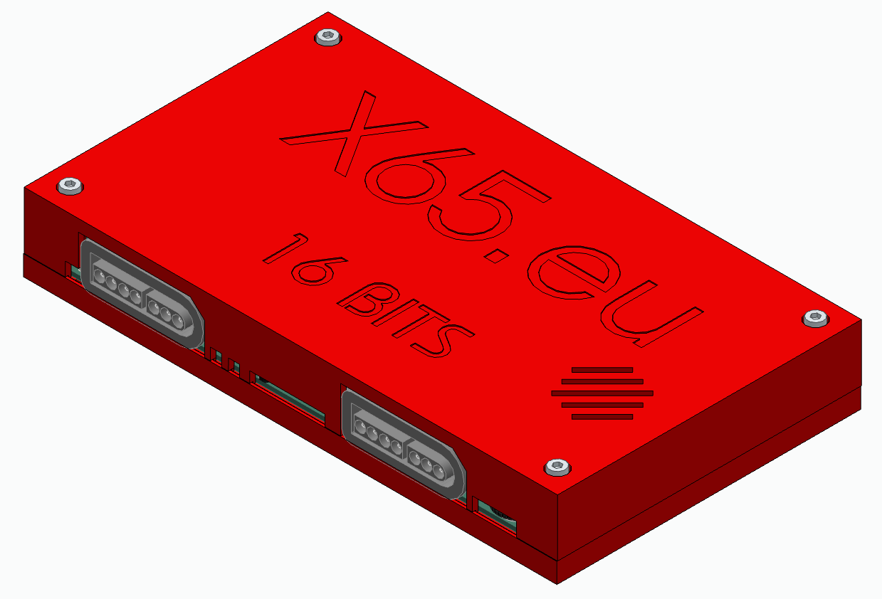
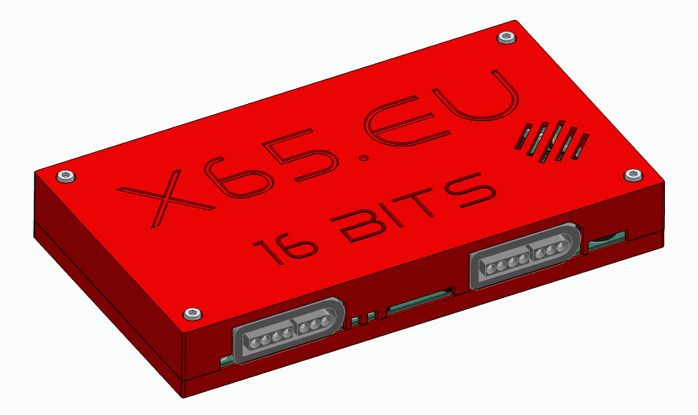
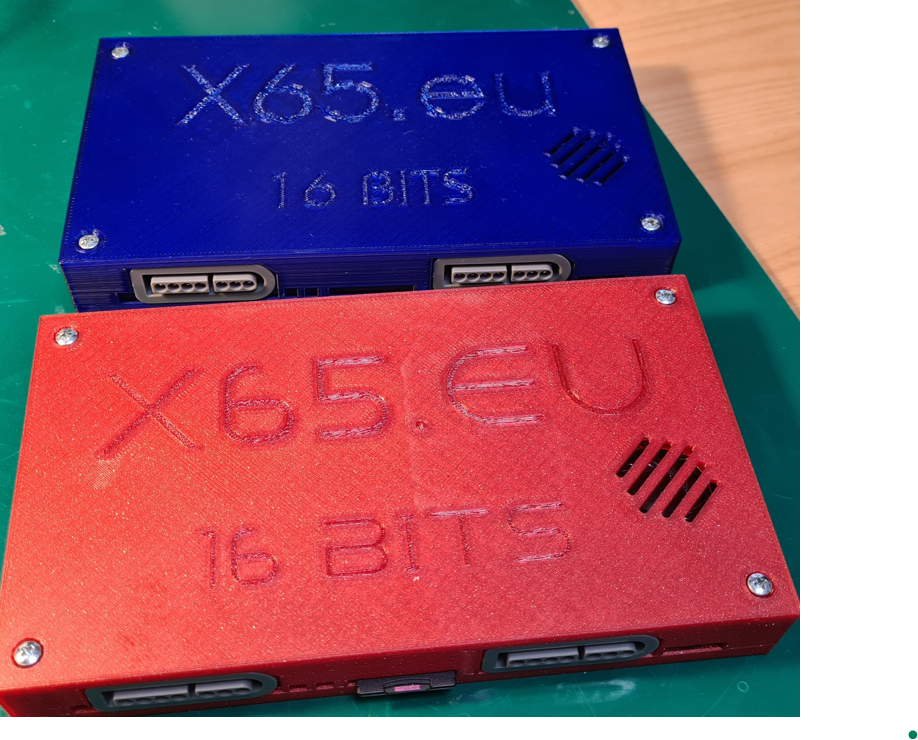
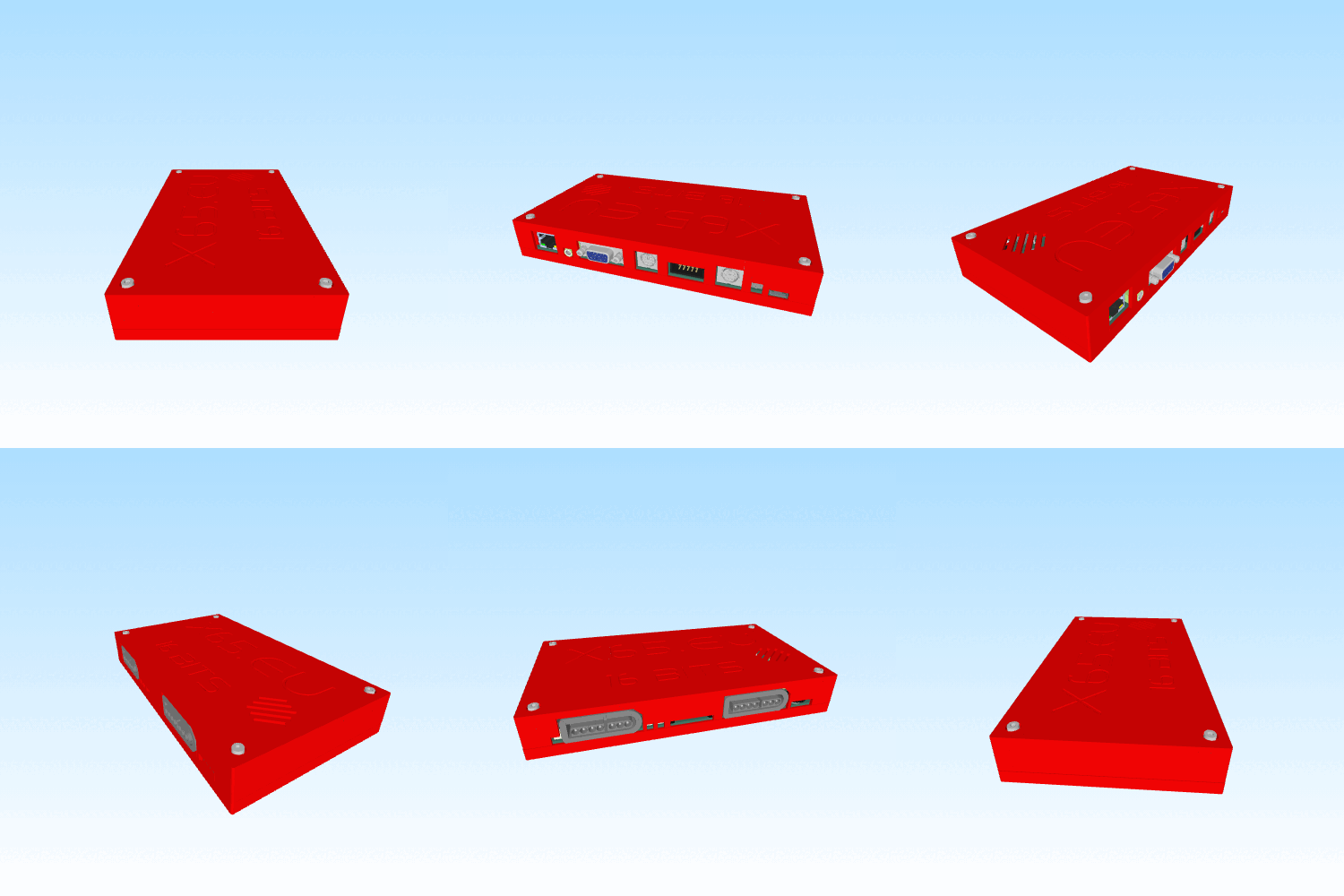
    * 3D box design...
    * posibilities for own software besides CX16: Forth OF816 (partly implemented), Fastbasic, Mad-Pascal, GeckOS...
    * update x65.eu landing page
    * and so forth...

    During the summer I have received a couple (2) of emails with comments: by Eric from France and by Matej from Slovakia.

    Eric would preffer the X65 in an ATX form-factor: an X65 ATX motherboard that could be inserted in a standard PC case, with many extension slots for plugging of extension cards. He would like to use such computer for automation. He could develop control programs in Basic or C, and he plans to develop own expansion cards: mainly for communication but also for audio processing. The computer would be used as an input/control/display front end.
    The PMOD connector, which the X65 SBC supports in HW, is not stackable and lacks mechanical fixing points. It is not suitable for deploynment of an application to a customer and it is very "timid" opening to the outside world.

    Matej owns Atari 130XE with many extensions (1MB RAM, 2x Pokey sound, SD-Drive, VBXE graphics card).
    He is interested in CX16 but he is disappointed with low availbility/long waiting times in the e-shop and relatively high cost. He is interested in running Dreamtracker on CX16. He can write software in MadPascal. He offered to design a 3D-printable box for X65. He requests if I could send him a prototype of the X65 SBC; we agreed that I would build one for him for the cost of components.

  • Video-Terminal for the Forth OF816 Interpreter

    Jara04/09/2024 at 19:43 0 comments

    In the previous post I have mentioned that I am working on a port of the 32-bit Forth interpreter OF816 to my X65-SBC, an 8/16-bit retro computer that I am building. The software runs on the X65-SBC in the 65C816 processor, but the user textual input and output was so far realized via the USB/UART interface terminated on a host PC in a terminal emulator (e.g. putty).

    As the next logical step, shown in the demo below, I have implemented a video text terminal using the VERA chip and the VGA output from the X65-SBC. VERA is the computer’s video chip implemented in an FPGA. VERA has 128kB of internal VRAM and could be configured in various graphics modes, typically generating a 640×480-pixel resolution screen. For the purpose of a textual terminal output I am configuring VERA to display 80 columns by 60 rows of visible characters. Each character is 8×8 pixels, and each character can have one of the 16 foreground and background colors.

    The following short demo shows the OF816 code running on the X65-SBC computer with the video terminal output from the VGA port (for the purpose of a youtube demo the VGA signal is captured in a PC and displayed in a live window). The text input to the OF816 software is (still) provided over the USB/UART (putty); this is a work in progress to utilize the PS/2 keyboard of the computer, next time.

    Demo

    VERA Mode Configuration

    VERA is configured in the 80x60 character text mode with this code snippet (65c02 assembly):

        ; DCSEL=0, ADRSEL=0
        stz   VERA_CONTROL_REG
        ; Enable output to VGA 640x480, enable Layer0
        lda   #TV_VGA | LAYER0_ENABLE
        sta   VERA_VIDEO_REG
        ; DCSEL=0, ADRSEL=0
        stz   VERA_CONTROL_REG
        ; characters are 8x8, visible screen 80 columns, 60 rows.
        ; Complete screen is 128x128 characters, 8x8 font
        ; # Layer0 setup: Tile mode 1bpp, Map Width = 128 tiles, Map Height = 128 tiles
         ; ==> 16384 tiles, each 2B => 32768 B
        lda   #MAP_WH_128T << 6 | MAP_WH_128T << 4 | BPP_1
        sta   VERA_LAYER0_CONFIG_REG
        ; map entries start at address 0 of VRAM, and occupy 32kB
        lda   #mapbase_va
        sta   VERA_LAYER0_MAPBASE_REG
        ; tile (font) starts at 32kB offset
        lda   #(tilebase_va >> 11) << 2
        sta   VERA_LAYER0_TILEBASE_REG


    The “map” size is 128×128 characters (tiles), but only 80×60 is visible on the screen. Using registers VERA_LAYER0_HSCROLL_REG ($9F30) and VERA_LAYER0_VSCROLL_REG ($9F32) it is possible to smoothly scroll the 80×60 viewport over the larger 128×128 map. This feature is typically used in 2D scrolling games. VERA allows map widths and heights from 32 to 256 tiles (32, 64, 128, 256). Tile width and height could be configured to 8 or 16 pixels; for the textual display we use the 8×8 pixel tiles.

    Memory requirements for the map are: 128 * 128 tiles = 16834 tiles. Each tile consumes 2 Bytes of the VRAM, for the total tile-buffer memory 32768 B = 32kB. VERA supports multiple Tile Modes that differ in colour depth and in the support for additional features (e.g. V-flip, H-flip). For the textual display the most suitable mode is the “Tile mode 1 bpp (16 color text mode)“, as described in the VERA documentation:

    In this mode the first byte of each map tile is the 8-bit character index (ASCII code), and the second byte contains a 4-bit background and a 4-bit foreground colour of the tile. To display a text in the 80×60 characters screen grid you just set the character index and colours for particular tiles.

    Font Data

    The 8-bit character index in each tile points to an 8×8-pixel “picture” (glyph) that shall be drawn at the tile position. This is the font data, and the font needs to be loaded in VERA’s VRAM during initialization phase. Each character in the font is 8×8 monochrome pixels, i.e. 8*8=64 bits, and that is 8 Bytes. The font has 256 ASCII characters, so the font data is 256 * 8 = 2048 B = 2 kB in total. The picture below shows the first 576 Bytes of the font...

    Read more »

  • 32-bit Forth for the X65 with 65C816 CPU

    Jara03/22/2024 at 21:11 0 comments

    I am working on a port of the 32-bit FORTH interpreter OF816 for my X65-SBC computer with the 65C816 CPU. The OF816 was created by mgcaret and is available on github. I made a fork of the OF816 project  and added a new branch for my work: x65-sbc.

    The OF816 already supports a couple of 65C816-based systems: GoSXB, Apple IIgs, Neon816 and the W65C816SXB. I added a new subdirectory X65 in the platforms directory and initially copied from the Neon816 port, because it seemed the simplest.

    The initial support for X65-SBC was not difficult to program. I modified the `_system_interface` routine in the `platform-lib.s` to work with the USB/UART registers that are implemented in NORA FPGA on the X65-SBC. After adjusting memory addresses in a linker script, I was surprised that this minimal OF816 port worked on the first try.

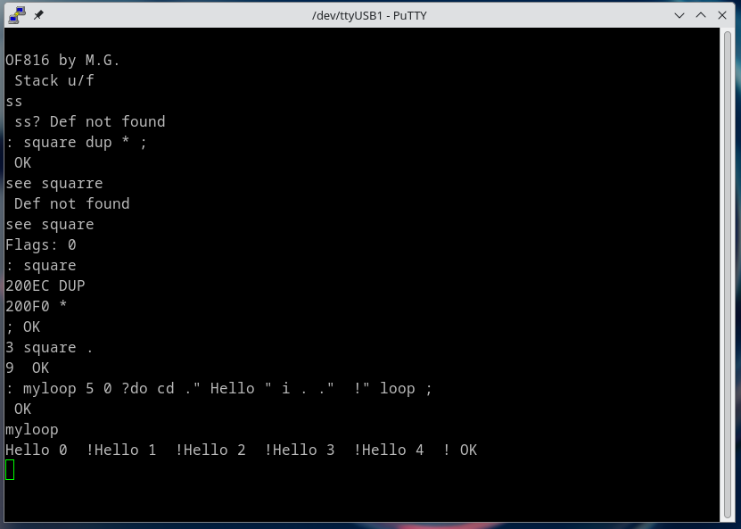
    The screenshot above shows a terminal emulator on Linux PC connected over USB/UART to the X65-SBC computer running the OF816 FORTH interpreter. Since I am just a beginner in the FORTH language, it took me a few lines to enter and run a Hello World loop.

    This OF816 FORTH port currently communicates over the UART on the X65-SBC. Therefore the user interface is on the host PC for now, and the keyboard and video output on X65-SBC are not utilized.
    This is just temporary as I am already working on a basic virtual terminal (i.e. screen editor) for the X65-SBC and the first "client" will the OF816 interpreter.

  • Reading of 6502/65816 CPU Registers by a PC-based Debugger

    Jara03/03/2024 at 20:08 0 comments

    Modern microcontrollers and microprocessors have built-in facilities for external debuggers to read/write registers, set breakpoints and generally fully control the CPU. This is one of the main usecases of the standard JTAG interface. The 6502 and 65816 CPUs were created more than a decade before the first version of JTAG was even defined. They contain no support for external debuggers whatsoever.

    To overcome the lack of debugger support, the system bus controller "NORA" in X65 implements the necessary functions for a debugger running on a host PC (with Linux or Windows) and connected over the USB-C port. With this support in NORA a debugger can control the 6502/65816 CPU at the instruction level. 

    One of the basic functions of a debugger is to read out the contents of the programmer visible CPU registers. This log entry describes how this is done in the X65 computer. ....

    Read more »

View all 5 project logs

  • 1
    Github

    All project data is kept on the github server.

    The PCB is designed in Kicad 7. The kicad project directory is in pcb/x65-sbc-revB1 (please check if there is a newer version in the meantime).  Direct link to schematic in PDF.

View all instructions

Enjoy this project?

Share

Discussions

Similar Projects

Does this project spark your interest?

Become a member to follow this project and never miss any updates