 ELECTRONOOBS
-
1Part 1 - The PCB
What’s up my friends, welcome back. This below is the PCB that I’ve designed for my project. I’ve tried to make it as small as I could so it could fit inside of a basic wall electric box. This project works at 220V so make sure you stay safe and never touch the exposed wires.
Since it works at 220V AC and the ESP32 needs 3 to 5V DC, I’m using a voltage converter module. That is very small and will give us a very steady 12V DC and 1 amp of current which is more than enough. Then, on the other side I’m using two linear regulators to get 5V and 3.3V. The ESP32 is controlling an SSR or solid-state relay. And that relay is connected to the output where we can connect our load. I’ve placed some pins around in case that you want to connect anything else to the ESP32. So guys go and download the GERBER files for the PCB from this post. Then go to PCBWAY.COM and click the quote button. Add the size of the PCB (71 x 30mm), the amount of boards that you want and select a color. Since the green one is made faster, I selected the green solder mask. Save to cart and on the next page click the upload button. Now upload the GERBER files you’ve just downloaded from below my video. Make the order and receive my PCB in just a few days. Give them a quick inspection, but as always they look great. -
2Part 2 - What we need
Let's see all the needed parts and also check the schematic for this project below in order to know where to connect each part. We need the 220V to 12V regulator, the solid-state relay, an ESP32S smd version, some SMD capacitors and resistors, a diode, a small BJT transistor, some LEDs as well and the input and output screw terminals. This animation above should be the finished PCB Later we will see how to connect the PCB to mains input and the 220V AC load.
- PCB GERBERs: Get PCB Files
- 1 x ESP32S Wroom: LINK Aliexpress (scarcity in 2022)
- 1 x SSR relay 5V: LINK Aliexpress
- 1 x 220V - 12V 1000mA Converter: LINK Aliexpress
- 1 x S8050 NPN: LINK Aliexpress
- 1 x M4 diode: LINK Aliexpress
- 1 x AMS1117 5V: LINK Aliexpress
- 1 x AMS1117 3.3V: LINK Aliexpress
- 2 x 2Pin screw terminal: LINK Aliexpress
- 3 x 0603 LEDs: LINK Aliexpress
- Female PCB Pins: LINK Aliexpress
- 4 x 1206 10uF Capacitor: LINK Aliexpress
- 3 x 0603 100nF Capacitor: LINK Aliexpress
- 4 x 0603 10K Resistors: LINK Aliexpress
- 1 x 0603 1K Resistors: LINK Aliexpress
- 2 x 0603 330R Resistors: LINK Aliexpress
- FTDI UART Module: LINK Aliexpress
![]()
-
3Part 3 - PCB Schemati
The schematic is quite easy. The basic configuration of the ESP32 chip with pullups to 3.3V for Enable and RST pins. The converter module give us 12V so we connect that in series with the AMS1117 regulators of 5 and 3.3V. The Relay circuit is simple. We use a BJT to connect pin 4 of the SSR to GND so we turn it ON. That's how when the D12 pin is HIGH, the NPN is ON so the Relay as well. We also have the UART pads for programming.
![]()
-
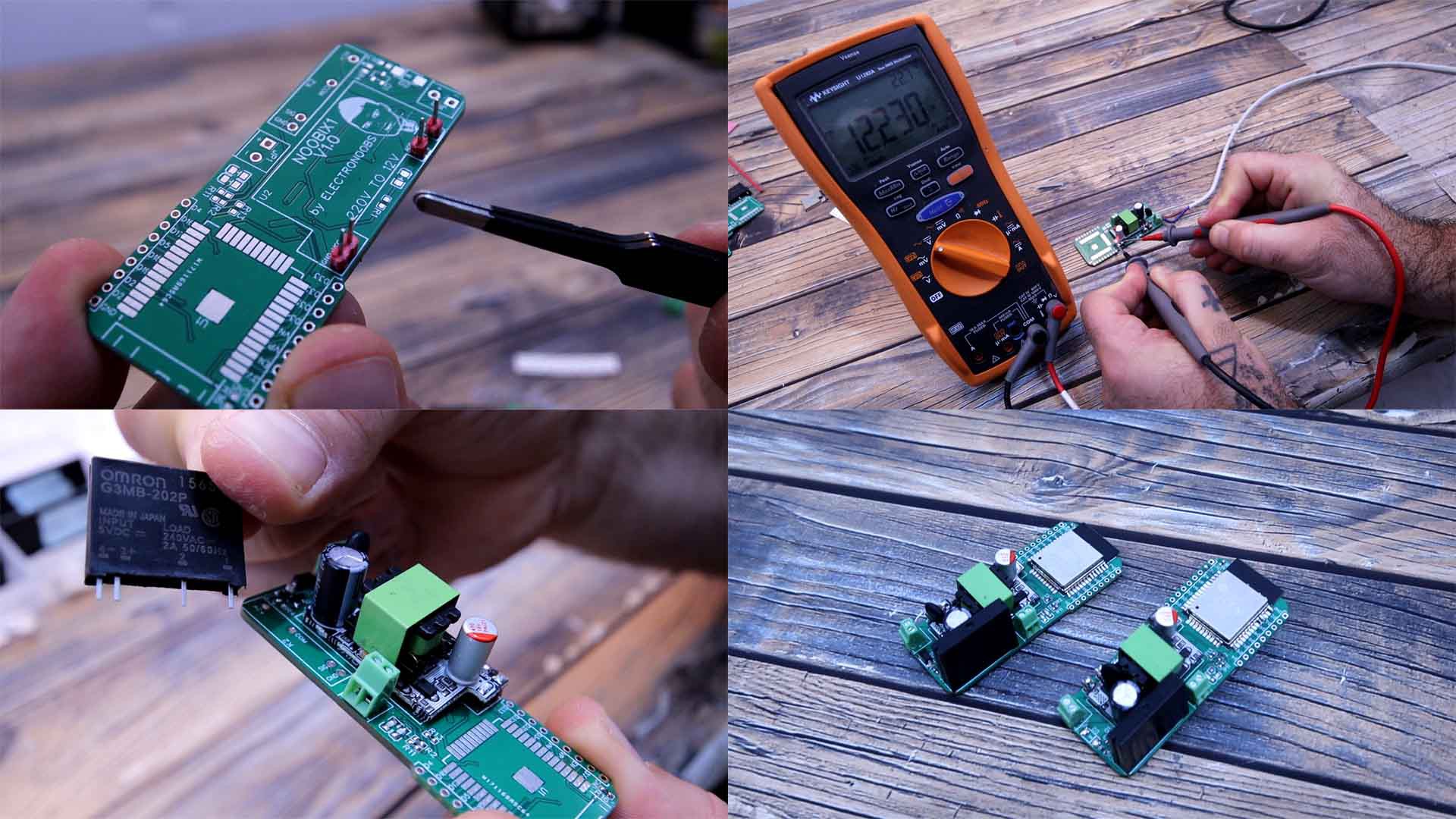
4Part 4 - Assemble the PCB
First I solder the voltage converter module. For that add 4 male pins. And on top of those pins we add the converter and we solder it. I also add the input and the output terminals. Then I carefully connect a 220V AC cable at the input. Be careful, and then connect it to power and check the voltage output of the module. If it is around 12V, we can continue. Then I solder the 5V and 3.3V regulators on the back of the PCB. Then I do the same and check the voltage output with my multimeter. Now that we have the voltage regulation part we can add the rest. I solder all the small resistors, capacitors, diodes and LEDs. I add in place the SSR. Finally I solder the ESP32 and the PCB is ready but we need a code uploaded with an external FTDI programmer connected to the UART pads on the back of the PCB.
![]()
-
5Part 5 - Website + Database
Please check my previous tutorial about IOT with the ESP32 in order to understand more because I won’t go over those steps again. In the video below you learn how to make the website, the database, the internet connection and so on. Follow the same steps and get a website domain and a hosting service. Create a database and then create a table called LED_status with two columns, one named ID and another named status. Create a new row with ID 1 and status 0.
Then download from this post page a .zip. Extract that ".zip" and you will get three PHP files together with the CSS file and two images. Open the connection.php file and place your values from your database for the host, name, username and password. Now save this php file and then you must upload all 3 files to your website directory together with the CSS and the pictures. If you go to your website you should now have a button like this one that should toggle the LED status value on the database table from 0 to 1 and from 1 to 0. -
6Part 6 - Arduino CODE
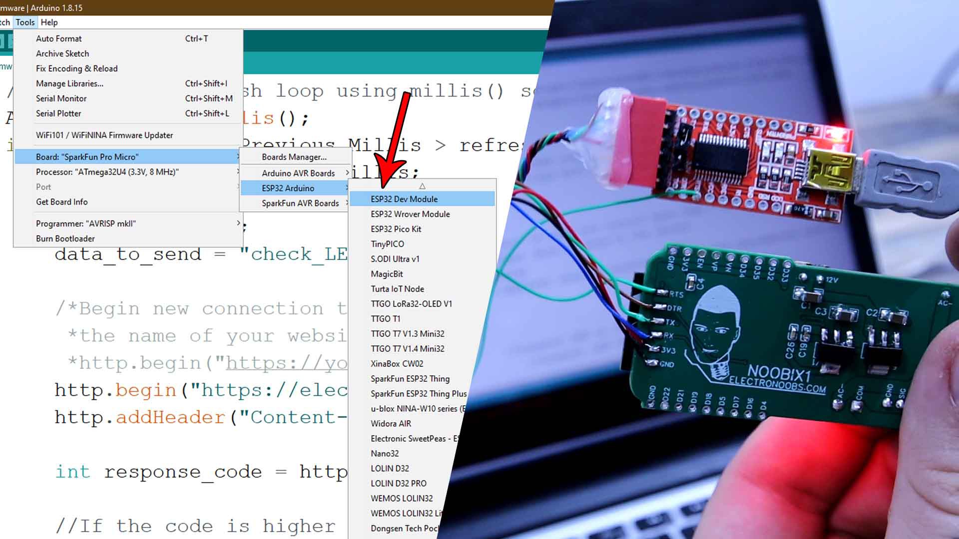
Now download the Arduino Code from below. Read the instructions in the code line by line. First, you have to change your wifi name and password. Then scroll down and in the http.begin function change the website from "electronoobs.com" to the name of your website. See in the previous video how to install the ESP32 boards. Once you do that, go to tools, board and select the ESP DEV MODULE board. Connect wires from an FTDI module to the PCB:
FTDI Noobix RX TX TX RX DTR DTR RST RST GND GND 5V 5V Then in Arduino, select the COM and upload the code. That's it.
![]()
-
7Part 7 - Full Tutorial Video
Now as you can see in the tutorial video, each time I toggle the button on my website, the LED on the NOOBIX board is also turning on and off. But we can also connect it to high voltage. Connect a 220V load at the output. Then we add a cable at the input and connect 220V AC. The board should automatically turn on. Now I go to my website and as you can see, we can toggle the light bulb on and off. And we can do this with any device. And remember that this is not a local connection. This works via the internet so you could control the NOOBIX module from anywhere in the world with a simple internet connection. Now I could add multiple modules and change the web interface with multiple buttons. I give an ID to each one and I could control more than just 1 NOOBIX. So guys get all the files from above and create your own IOT NOOBIX module with my PCB, Arduino code and PHP files. If you know PHP and CSS coding, you could create a better website or even a mobile App so good luck with that, it should be interesting.
NOOBIX IOT
The PCB on this project is called "NOOBIX" and gives you full IOT control for anything.


Discussions
Become a Hackaday.io Member
Create an account to leave a comment. Already have an account? Log In.