James Pilgrim
-
First > 100 mph Shot
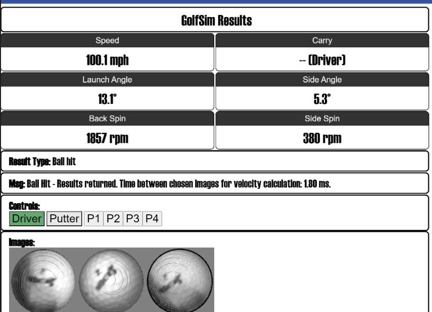
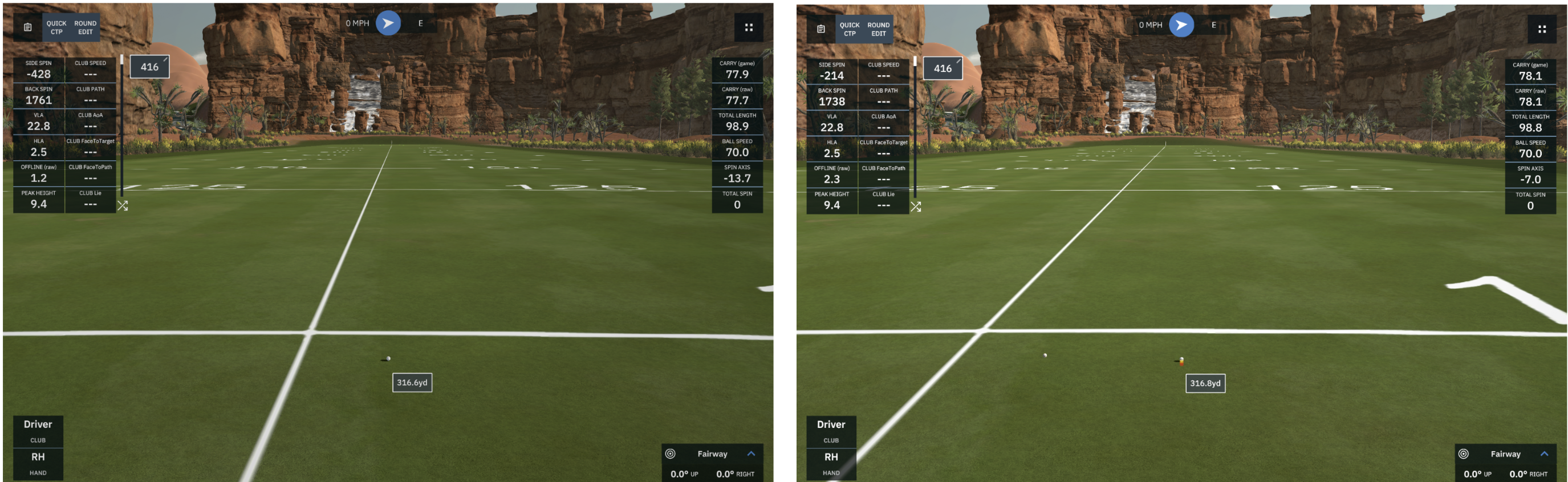
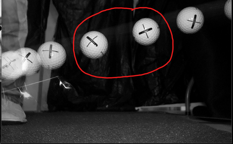
05/23/2024 at 21:16 • 0 commentsOk, so that's not very fast, but when testing something today, I took a club and just tried to really wack the ball. And I noticed that for the first time that I can remember, the system recorded a shot (barely!) over 100 mph (45 m/s). Sadly, I can't hit the ball a whole lot faster than that, but it appeared to be recorded correctly. There was also plenty of additional room on the screen for the strobe pulses to be pushed further apart and further to the right of the screen. That means that higher speeds should not be a problem.
![]()
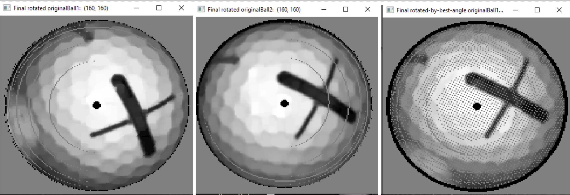
Unfortunately, I had the "on" strobe set to an unusually long time (>30uS), so that may have contributed to the blurring that is visible in the ball-spin analysis images. Which in turn resulted in an inaccurate spin measurement as seen in the mis-match between the second ball image and the as-calculated-spin ball (third ball image). Still, kind of satisfying.
-
Faster Shot Processing
05/22/2024 at 17:23 • 0 commentsThe LM is currently down to about 5 seconds delay between hitting the ball and seeing the shot in the golf simulator. This includes full processing, including 3D spin down to 1 degree in each axis. See video here.
This speed is not as fast as it needs to be, but is getting closer. The recent speed up is due primarily to utilizing more processing cores, turning down debugging, and moving up to a Pi 5 from a Pi 4. Additional speed increases should be available by decreasing the network traffic that is currently going on after a shot. I still think the LM should be able to get to less than two seconds.
-
First Commercial LM (Uneekor XO) Comparison!
05/17/2024 at 23:34 • 0 commentsToday for the first time, we were able to make a few comparisons of the DIY Launch Monitor's outputs to a commercial LM. It’s also the first time to test in a more professional simulator environment. The bed-sheet-over-PVC-piping-in-the-basement is still an option, but was pretty limiting. And funny. Instead, we now have access to a large simulator bay with the Uneekor overhead and running TGC 2019 (*).
The results? Well, pretty decent for a first try. See the example video here. Lots of work to do, obviously, and WTH is going on with the side spin (at least in this one test case)? We also need to stop truncating the output to integers in order to have a more meaningful comparison. Hopefully these aren’t difficult fixes. I’m not too unhappy right now in any case, given that the material costs of the DIY LM are around 1/20th of the cost of a Uneekor. However, I’m certain the DIY LM can do a lot better than it's current performance.
BUT, the main problem with the comparison environment was something I should’ve foreseen, but didn’t. The Uneekor also appears to use an infrared strobe. I never knew how it worked until I started this comparison, and it appears to run a high-speed IR strobe at all times once the ball is teed up. This is wreaking havoc on the DIY LM! See the bright-orange mess on the LM’s user interface in the video. Current ideas include trying to notch-filter whatever wavelength the Uneekor is centered on, as well as some type of filter to remove the linear ghost images of the golf shaft as it moves. I'm curious how other folks do comparisons of this sort (to the extent anyone has).
___________
(*) I’d really like to complete an interface to TGC 2019. The DIY LM already works with GSPro and E6. But no one at #2k Games (pr@2k.com) answers our emails, and I can’t locate a business contact there. Anyone who knows someone, please DM me!
-
E6/TruGolf Simulator Interface
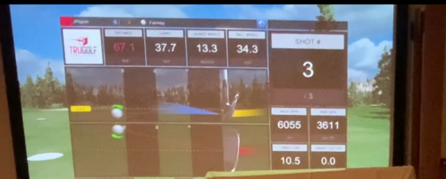
04/27/2024 at 21:44 • 0 commentsThe first version of the E6/TruGolf interface to the DIY Launch Monitor is now working!
![]()
BIG thank-you to the folks at TruGolf, especially Melissa and Ryan for their help and quick turn-around on questions. I’m super-appreciative that they (and GSPro) have been so supportive of what is currently a small Launch Monitor project.
Here’s a short video demonstration of a couple of shots: DIY Launch Monitor - E6/TruGolf Interface
We’re under NDA with TruGolf, so I can’t say anything specific about their API. However, suffice to say that it’s pretty sophisticated and exposes an impressive amount of functionality. I hadn’t spent much time with their product before now, and wasn’t aware of its breadth and depth.
The LM’s interface is pretty minimal right now (mostly just player info and shot data), but it will be fun to flesh it out further in the future. However, the next big push is getting the LM to be a lot faster when calculating shot data.
-
New Putting Mode and LM User Interface
04/23/2024 at 17:02 • 0 commentsUltimately, the system shouldn't care whether a player is putting as opposed to hitting a full-speed shot with a driver. But for right now, it's easier to accommodate the different image processing parameters in those two scenarios by telling the system when you're putting. I've got a plan to automatically switch between modes, but I'd like to get some higher-priority features going first, such as the TruGolfinterface and switching over to the Raspberry Pi 5.
The system can be set to putting mode either by using the build-in user-interface (see near the end of the linked video), or by using the golf simulate (in this case, GSPro) to select the putter as the current club. Once selected, the system configures itself for the slower putting speeds. I've been able to accurately determine putts as slow as 1.5 mph, and as fast as almost 20 mph.
The following video gives a little demonstration of a couple of putts.
-
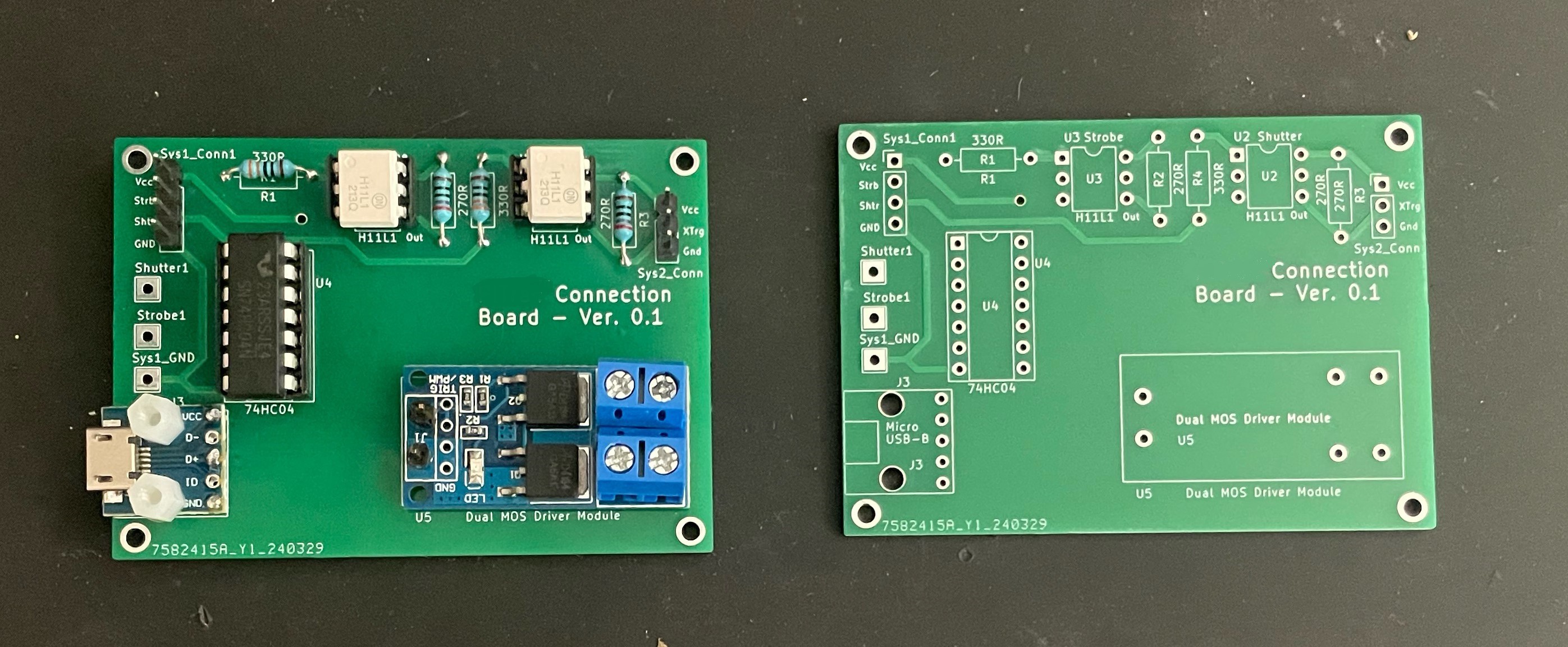
Printed Circuit Boards are Working!
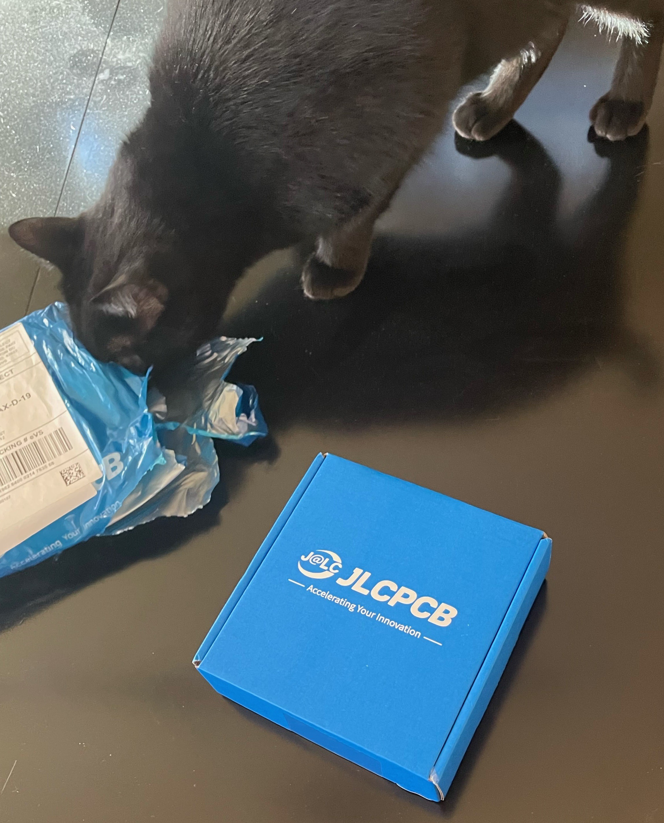
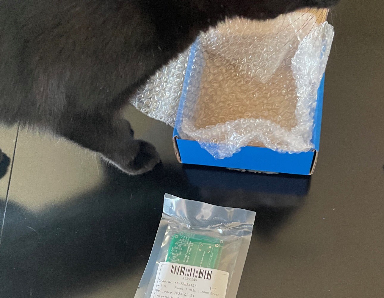
04/17/2024 at 18:11 • 0 commentsThe first run of printed circuit boards arrived today from JLCPCB. These are the boards that help connect the components of the system and also keep the high voltage strobe signals isolated from the fairly fragile Raspberry Pi GPIO circuitry.
The boards look good. Especially for the very low price that #JLCPCB charges for small boards like this. The entire thing, including (slow) shipping was a whopping US$ 3.64. I wasn’t able to get anything locally (which I would have preferred) for less than $300!
Here’s the unboxing pictures. I’m sure they’ll go viral soon...
![]()
![]()
It only took a few minutes to populate the board. By dumb luck, all the holes ended up in the right places! Pretty surprising given that this was my first attempt at having PCB boards manufactured and also because I'm using an unfamiliar CAD system. Of course, it's a pretty simple circuit, so maybe even I couldn't screw it up. ;)
Here’s the finished (populated) and empty boards:
![]()
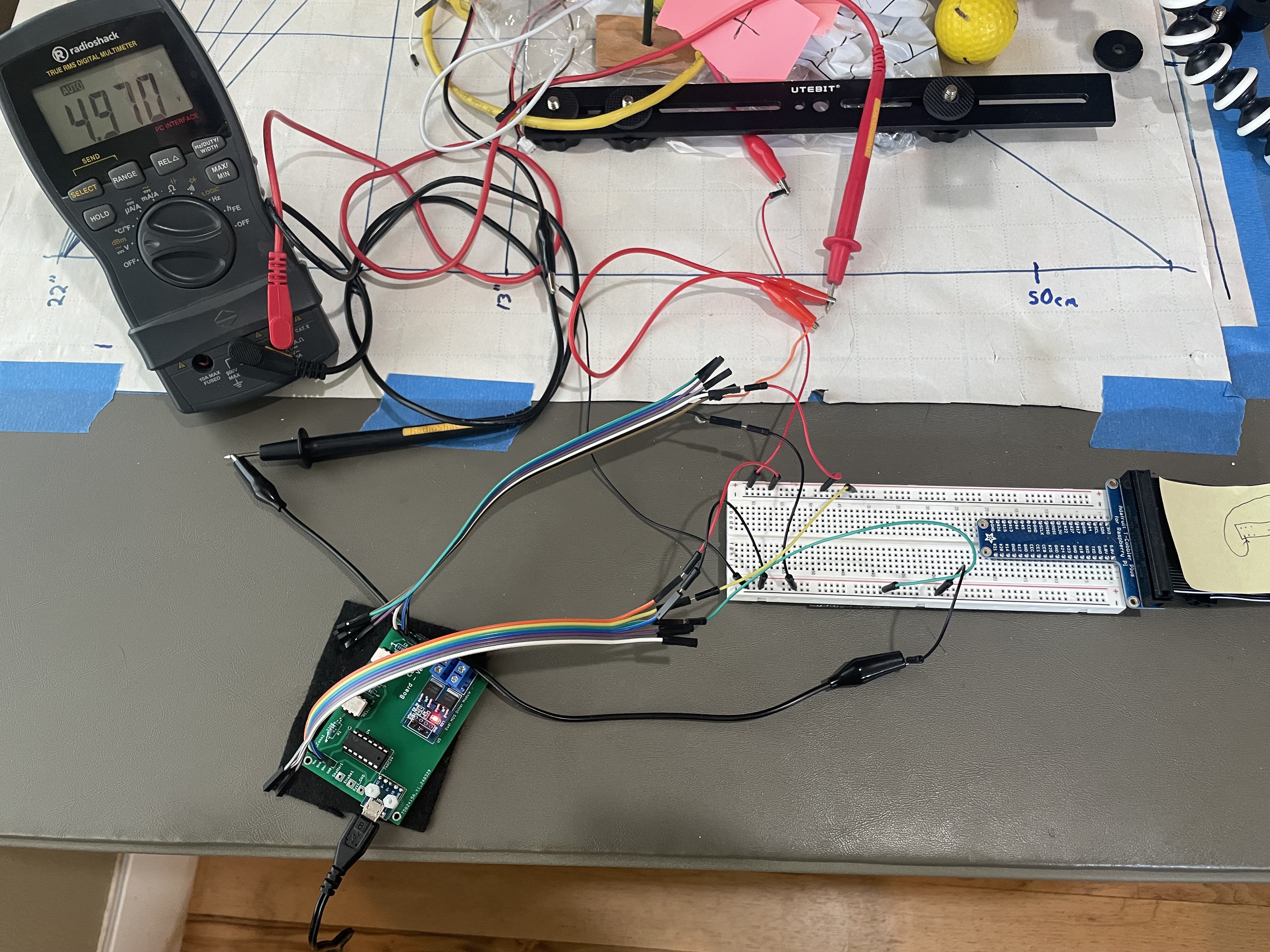
Most amazing of all, is that everything tested out and worked on the first try:
![]()
-
A Preliminary Accuracy Analysis - Spin Measurements
04/14/2024 at 20:31 • 0 commentsBackground:
Several folks have asked about accuracy and precision. That’s a big topic, so I decided to start on only a single aspect – spin analysis – and just provide a couple of examples. I haven’t worked out a formal, full, math-based error analysis yet, and am not certain I can. Instead, this log entry will just focus on providing anecdotal descriptions of the errors in what I believe are ‘typical’ scenarios. I’m not even sure that a math-only analysis is a reasonable goal – there are an awful lot of case-specific potential places for errors to creep in, and it may not be possible to enumerate them all. I’d also probably have to go back to my grad-school books on error analysis and remember all of that. Ugh. Of course, it would be great if this was all open source someday and some smarter folks could dig into the math and tear it all apart!
Another important background point is that a real “ground-truth” against which to compare the system is hard to find. You’d literally have to go to a real golf course, setup the LM(would have to be a very cloudy day to prevent the camera from being flooded with IR), and then measure the real-world distance, angle, etc. on the course and compare it to the results of the physics model in use by the LM/Simulator. I don’t have those facilities yet. :/ As an alternative, the analysis here will be focused on comparing a best-estimate of the ‘’correct’ ball spin using visual techniques against the ball spin determined by the LM. We’ll also make a comparison of how those difference(s) manifest themselves in pseudo-real-world coordinates in a simulator (here, GSPro). The carry distance will also, of course, be determined by the determined launch angles and velocity, but we’re focused on spin here. I’ll examine those measurements and the related accuracy in a later log entry. So, let’s start…
Analysis:
Spin speed accuracy is primarily governed by the accuracy of the angular delta measurement between the ball exposures and the accuracy of the determined time delta between the exposures. The former is currently most important. Precision is limited by the fact the system only deals with degrees of spin as an integer, so 1 degree is the upper limit on precision.
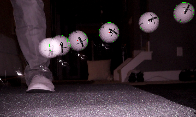
Let’s start with the following first example, where the strobed ball images are shown below. I chose these examples because they have a ball with strong registration markings that ended up facing the camera. That makes for easier visual analysis of the spin. These were also images where the Z-rotation was fairly substantive (these shots were using a 7-iron combined with crappy golf skills), and the X and Y rotations were near-zero, making it easier to focus on the back-spin.
The system chose two ball exposures from the above image to use for spin analysis. Those are the first two images, below, and labeled ‘1’ and ‘2’ above.
![]()
From these images, the system determined XYZ Angles (in degrees) of -5, 0, and 37. The -5 is side-spin, and the 37 is backspin. The 0 y-axis is “rifle-bore” spin, which is usually near zero. The system determined the time between the two images to be 3500uS (3.5 ms). The dark penumbra around the balls is a result of de-rotating the balls to a common frame of reference. That de-rotation (reversed later in the processing) creates some dark edges because some of the back of the ball (to the camera) has no information when rotated around to the front in 3D. The small dots (especially on the third image) are a result of the 3D/2D projection/de-projection operations.
In order to provide a visual sanity-check for the player, the system reproduces the first ball image rotated by the determined angular deltas, and shows that image as the third image above. In a perfect world, the result of rotating the first image by the delta angles should produce an image that looks exactly like the second image. In order to do a more precise analysis, an on-screen protractor was used to estimate the angles of the second ball relative to the first one. This is just a visual approximation, as we’re not measuring from the true axis of rotation. However, given the primarily-z-axis spin, it should be pretty close.
![]()
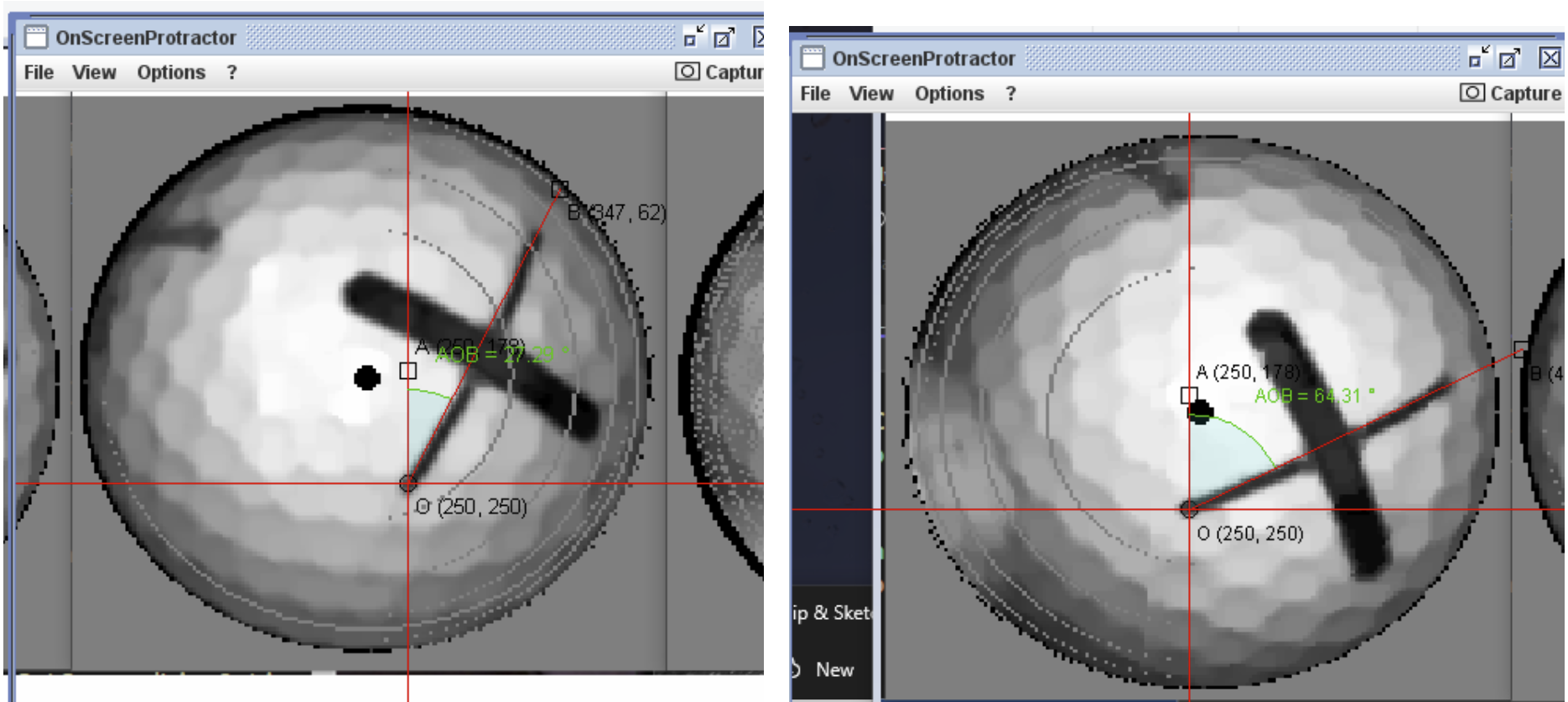
The first angle is 64.31 and the second is 27.82. Thus, the approximate Z-angle of rotation (ignoring the two other axes) is: 64.31-27.82 = 36.49 degrees. You get about the same number if you measure from the center dot in the middle of the ball image. That makes the error about 0.5 degrees.
The X (side spin) rotation error is larger, especially relative to the very small actual side spin. It is a little hard to measure this angular error very accurately, but you can tell from the third (projected) picture that the “X” is a little closer to the center-dot than the actual (2nd) picture. But, just as an estimate, let’s say 2mm as the radius of each dimple, and with a 134mm circumference (all from the intergoogle). The error looks like about a 1mm difference compared to the 2nd image. That’s 1/134 * 360, about 2.7 degrees difference in the X axis.
In conclusion, the back-spin error is 0.5/37.0 = 1.4% too slow. Side-spin, 2.5/5 = a 100% over-estimate. Pretty significant in this instance! :/ That said, if a more serious, say, slice is something like 30 degrees, and if the side-spin error stays at two or three degrees, that’s maybe not too bad.
So how does this affect the spin RPM calculations? Well, 37 degrees in 3500us -> 1762 RPM. The best-guess for the actual RPM was 1738 RPM. A 24 RPM difference.
Calculated side spin was 428 RPM, but (potentially) should have been 214 RPM.
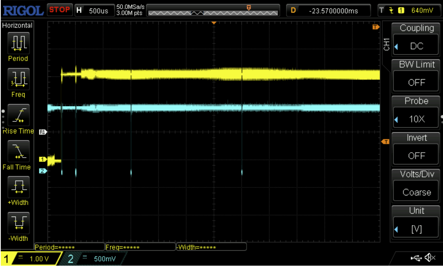
Now, let’s look at the potential error in the strobe timing. I have test-points on the system PCB to which I attached my oscilloscope. Some of the earlier-in-time pulses for both examples here are shown in blue, below:
![]()
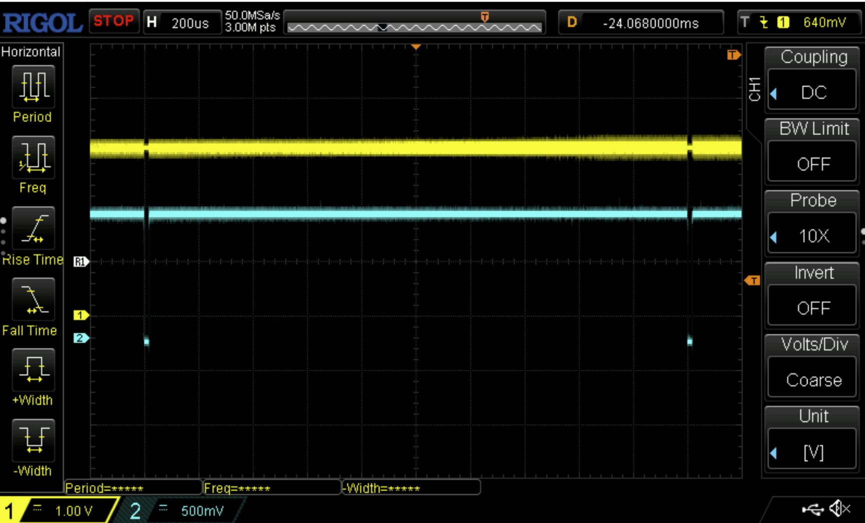
The question is, when the system determines that a certain amount of time has passed between two ball images, how accurate is that timing? Turns out, pretty darn accurate. For example, looking at what should be a 1 ms pulse interval at the largest magnification at which my scope will show two pulses (to make the example a little more convincing), there appears to be NO apparent error at all:
![]()
In the above picture, each small horizontal tick is 40uS. I can’t visually tell if there’s any error, but since I can’t see below ~4uS, let’s use 4uS as the possible error, just to be conservative. With an error that small, I just ignored the effect (which is pretty small compared to the angular errors).
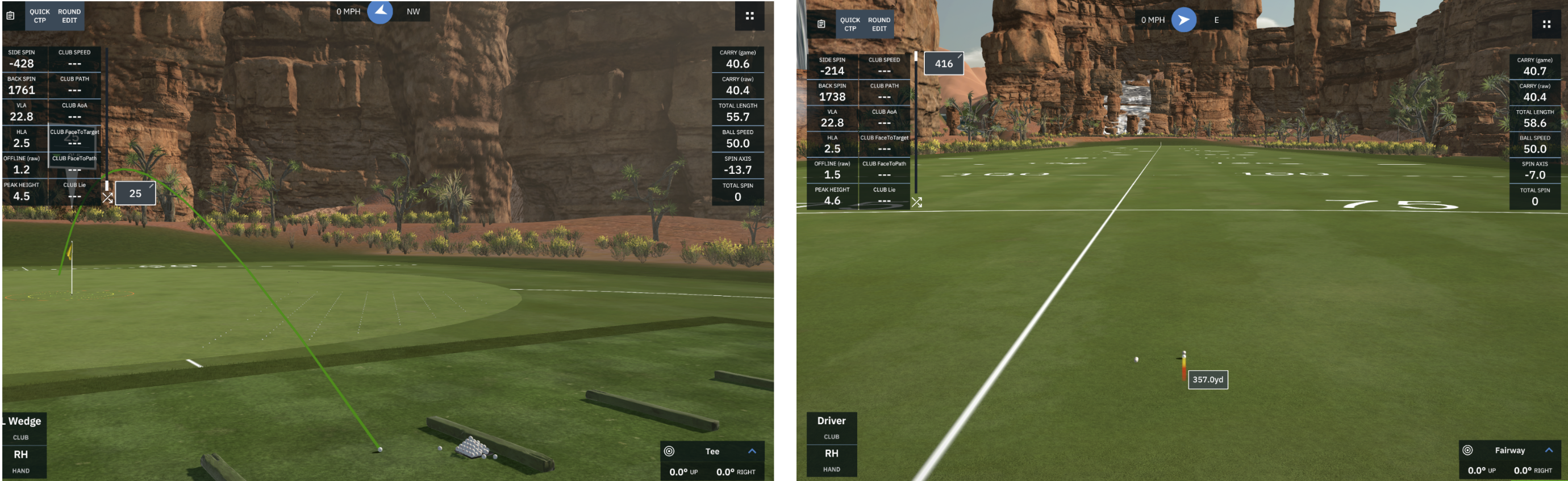
So— what does this mean in terms of your (simulated) game score? To determine the ‘real-world’ results of the above differences, I injected two shots into the GSPro simulator that differed only by the spin values. (Thanks to the #GSPro folks for their support!). The first two shots were, in order, the “correct” and “as-measured” data discussed above, except at 50mph. And the next pair was the same except for 70mph.
![]()
At 50 mph, the resulting carry difference is less than 3.6 inches (0.1 yards) of carry, and the total length difference is ~3.6 inches. Visually, I’d say the LM-determined ball is about a foot to the right of the “correct” ball. That’s due to the considerable 200RPM difference in side spins. (BTW, I screen-printed the second image about a quarter-second too soon, but wanted to catch the view before it returned to the original spot. You can see the second ball from an earlier run just ahead of the ball-in-flight.)
At 70 mph, the carry difference is again only a few inches, but the side distance is more like 3 feet. More work to be done on that!
![]()
Conclusions:
All in all, considering the use of the less expensive cameras and such, I think the DIY LM is making good progress in terms of spin accuracy. I believe that the spin accuracy can be increased using several techniques. The main tradeoff is between longer processing time for spin (I’d like it to be no more than a couple seconds). More time allows for a larger increase in the angular resolution of the algorithm. There should be some other ways to improve side-spin accuracy without costing more processing time as well.
In a later post, we’ll look at VLA, HLA, and velocity.
-
GSPro Interface Working
04/03/2024 at 18:11 • 1 comment -
Connection Board Prototype
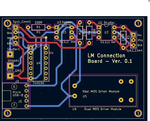
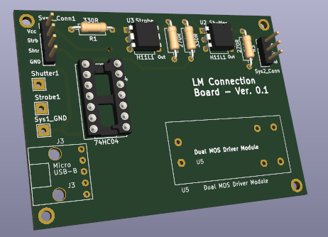
03/28/2024 at 13:34 • 0 commentsFinally getting around to documenting the small bit of circuitry in the project to make it easier for folks to produce. And as am added bonus, I get to learn KiCad! KiCad is a really great, free, open-source schematic and PCB layout tool.
The circuit board facilitates the connections between the hardware elements in the system. Those elements include the external shutter trigger on the PiCameras, the GPIO interfaces on the Pi computers, and the switching for the strobe light. Importantly, the connection board opto-isolates and provides separate ground planes for each subsystem, including the higher-voltage strobe power supply. That turned out to be important after I accidentally killed two different Pi units due to what appeared to be voltage transients from the strobe power supply getting to the GPIO chip on the Pi's. Now, each power supply area is a separate, hopefully-safe island of its own.
Shout out to the H11 high-speed opto-coupler chip. Very easy to use, and quite hardy.
Now if I can just find a low-cost, low-volume PCB manufacturer...
Follow-up: I'm trying JLCPCB, a low-cost China PCB factory. They were pretty easy to work with. I just uploaded my Gerber files and their website produced a quote and showed me a 3-D version of my board in a flash.
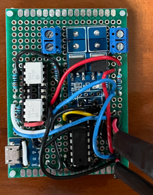
I hope to go from this mess of spaghetti:
![]()
To (hopefully) this:
![]()
![]()
-
Spin Analysis - Accuracy Verification
03/26/2024 at 13:57 • 0 commentsOne goal for the DIY launch monitor has been to be able to accurately determine the spin rate of balls in 3 axes without requiring any registration marks or other modifications to the ball (as some launch monitors need). The system now has some new processing artifact outputs and other refinements to spin analysis to confirm that the spin analysis is working.
The main idea is that because this is currently a new, and relatively untested system, we want to be able to give developers (and players!) the tools they need to visually sanity-check the spin analysis. One way to do that is to start by showing the two balls (an initial ball and a final ball that has undergone some spin) that were chosen for analysis. Then, take the spin angles that the system calculated for spin and apply them to the first ball and show how that looks. If things are working correctly, the first ball image (to which the spin angles were applied) should look to a human just like the original second (target) ball.
Particularly, depending on the trace-logging level, the system can now show the for-comparison balls at the same, normalized reference angle to make it more of an apples-to-apples comparison. Each image is pre-rotated so that both appear as they would if the image were seen in the center of the image, straight down the camera lens bore.
For example, see the results of the spin analysis that the system chose for the highlighted balls in the first image below, where the results are shown in the three later images. A ball with marks was used in this example, but that’s not necessary.
As shown above, it looks great! The exact determined angles above were (X, Y, Z): (4, 6, 64) degrees before being adjusted for azimuth and pan angles. Again, the system doesn’t require any registration marks like this ball has, but using a ball with marks does help for these visual sanity checks. Oddly, the marks can actually detract a bit from the analysis accuracy.
The little dots all over the images are the results of the proprietary fast 3D projection and un-projections that the system uses. These ‘holes’ could be interpolated away like most rotation algorithms do, but that’s not necessary for accurate spin-angle analysis. It could also chew up time and has other downsides.
PiTrac - The DIY Golf Launch Monitor
Launch monitor using low-cost Raspberry pi and camera hardware to determine ball launch speed, angles and spin