-
2024- 05-29
05/30/2024 at 10:52 • 0 commentsInstruction Book
Today, we finished assembling the book:
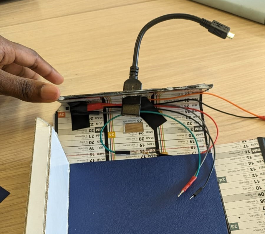
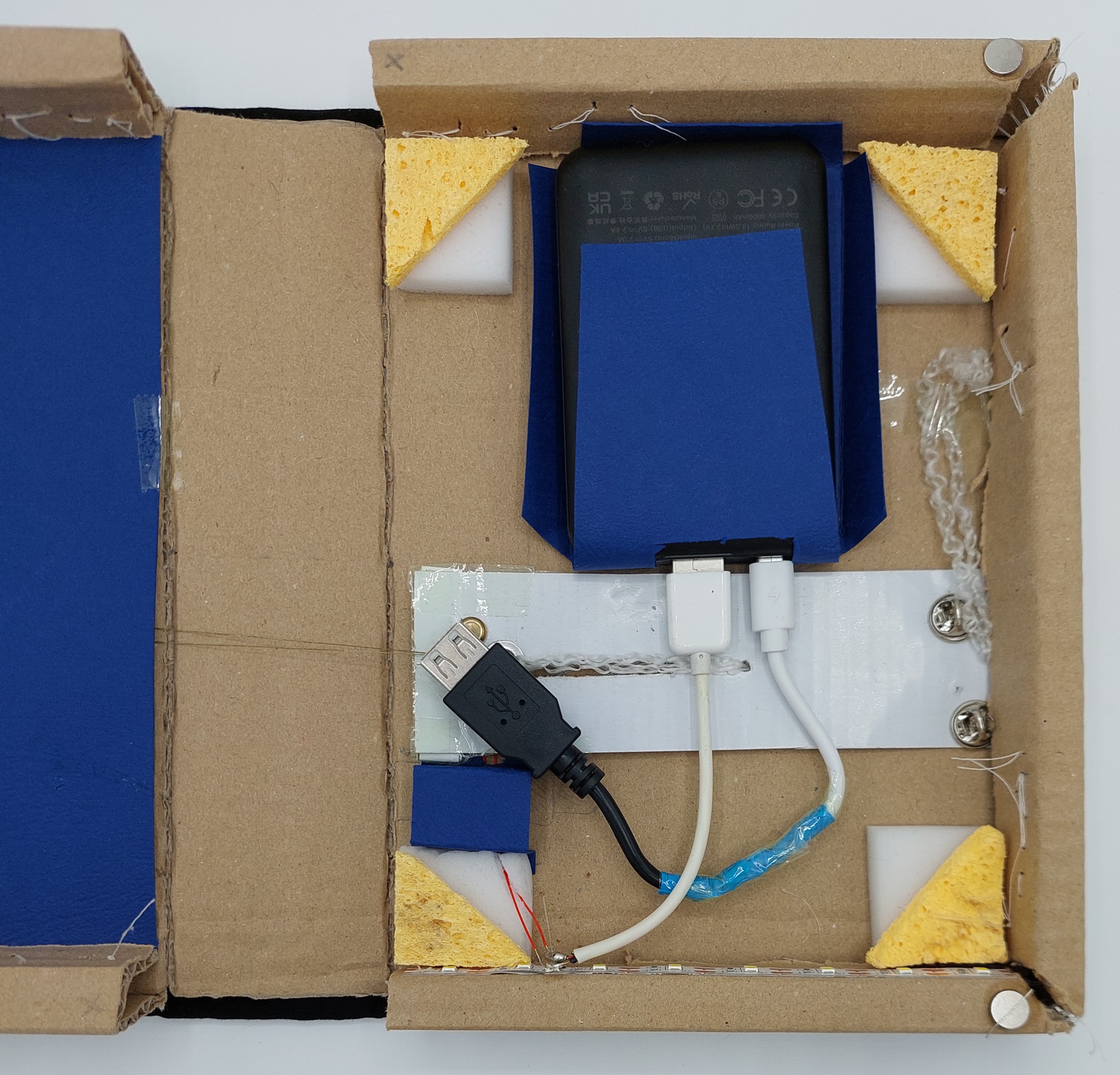
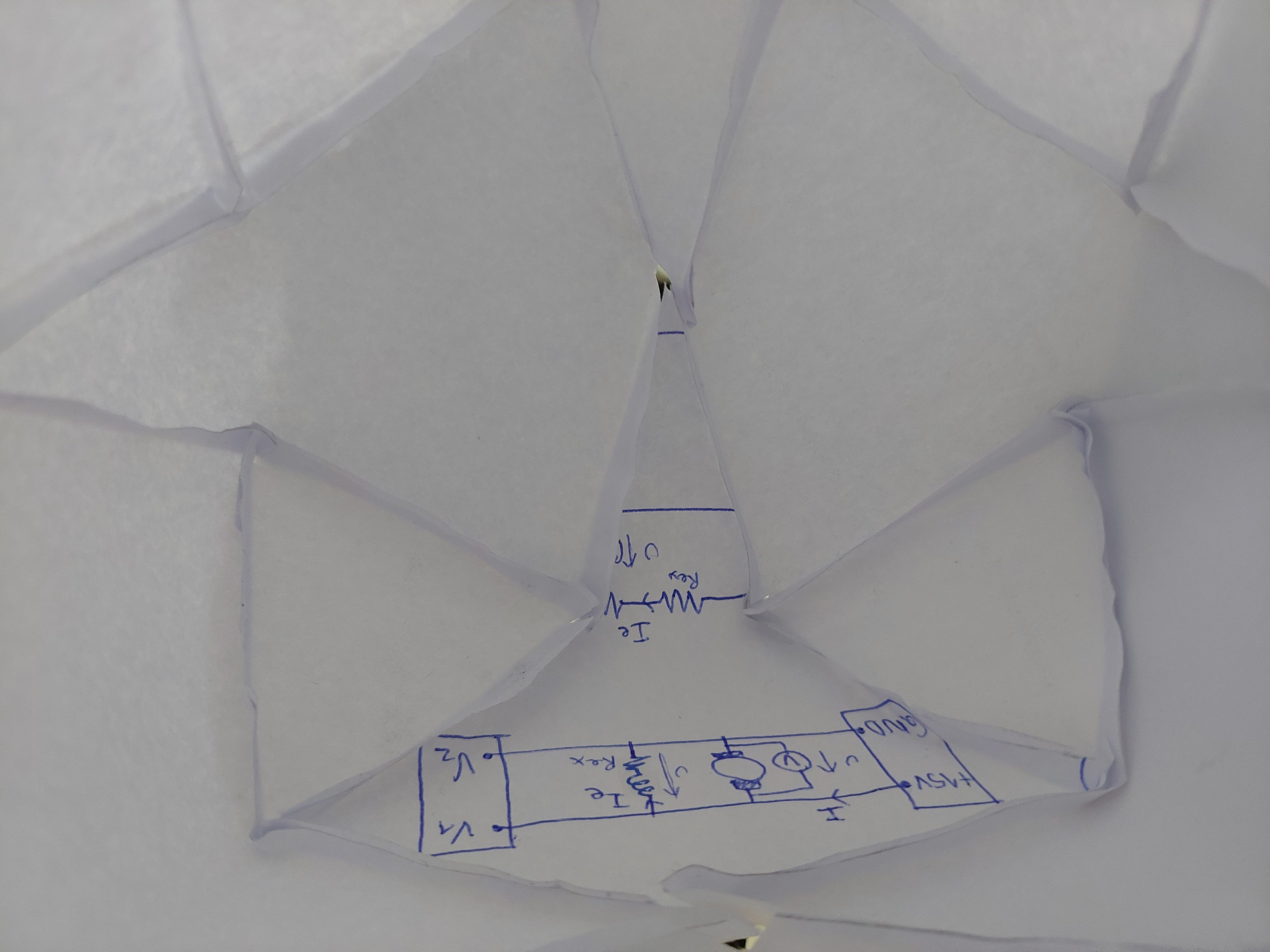
- hid the electric circuit inside the book's structure to make the inside neater and less busy with cables.
- cut the support for the rechargeable battery
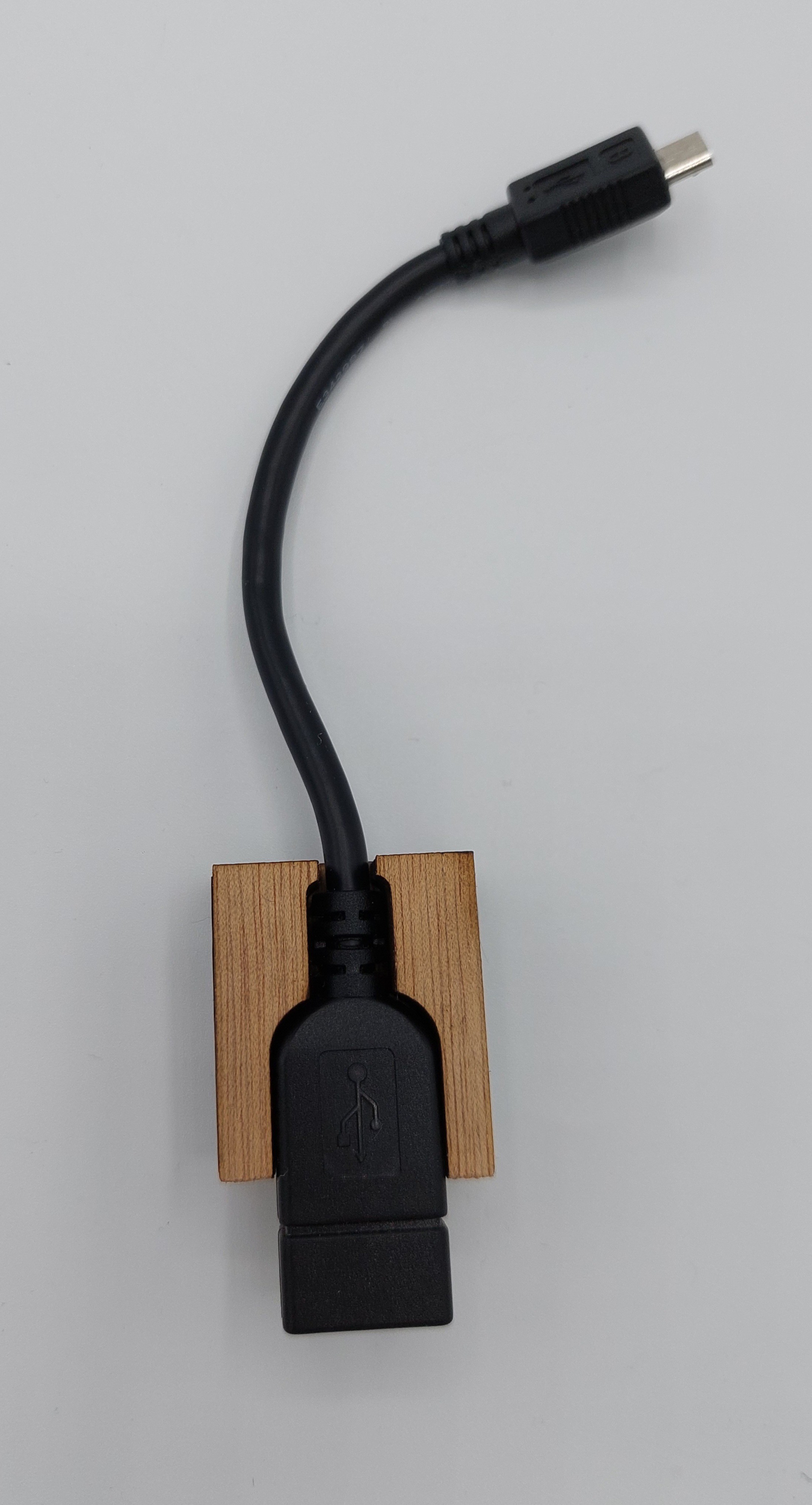
- cut the support for the charging cable
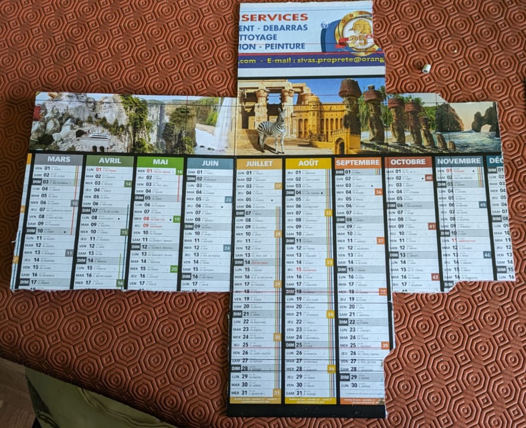
- measure and cut the cover of the book
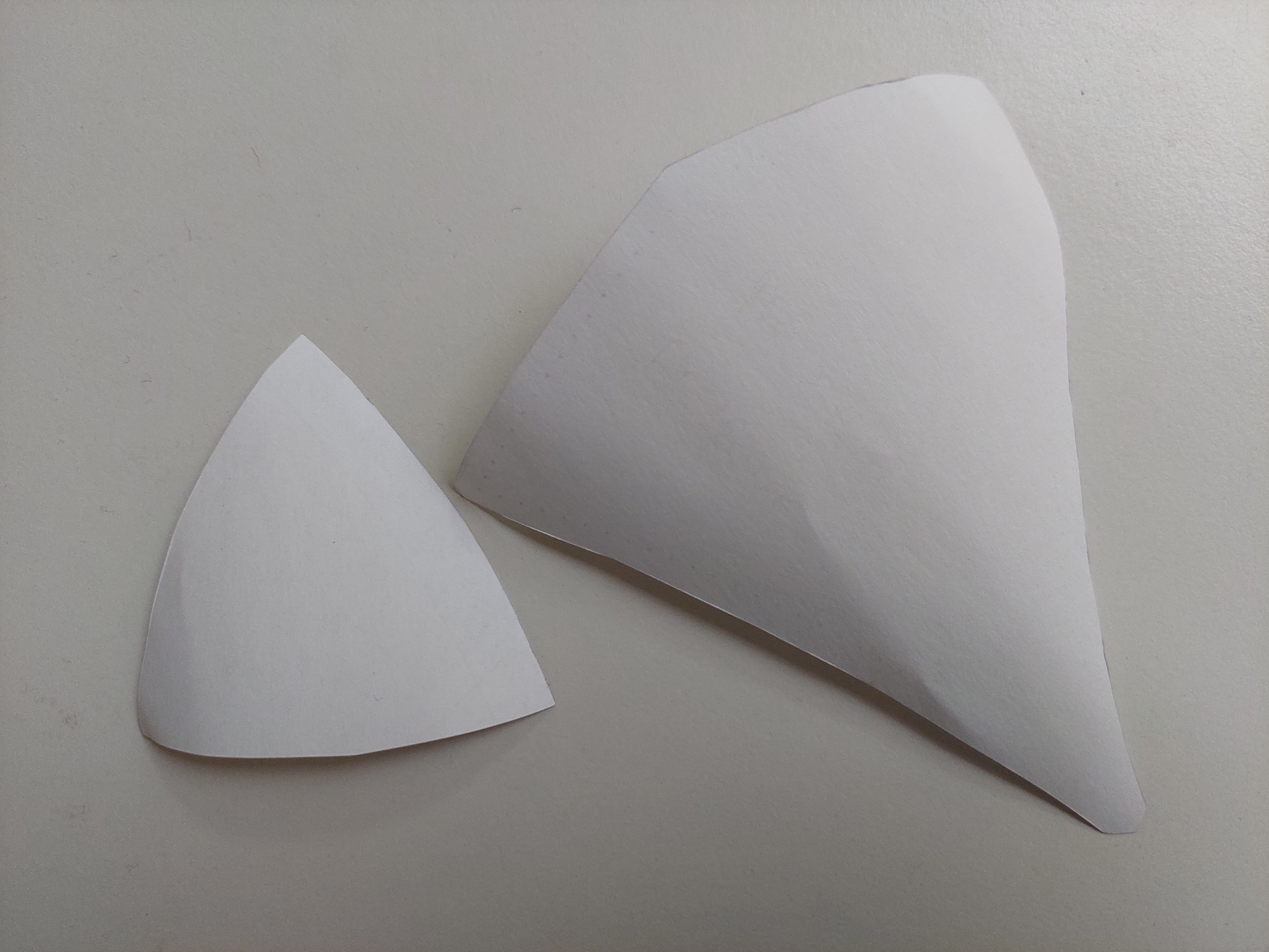
- assemble the cover following the same method as V1
Ball
Audio - DF Player
Last tests were made but still inconclusive so we decided to give up. We might try again later, but we cannot present any functional demo at the moment.
-
2024-05-30
05/30/2024 at 09:13 • 0 commentsFinishing the ball
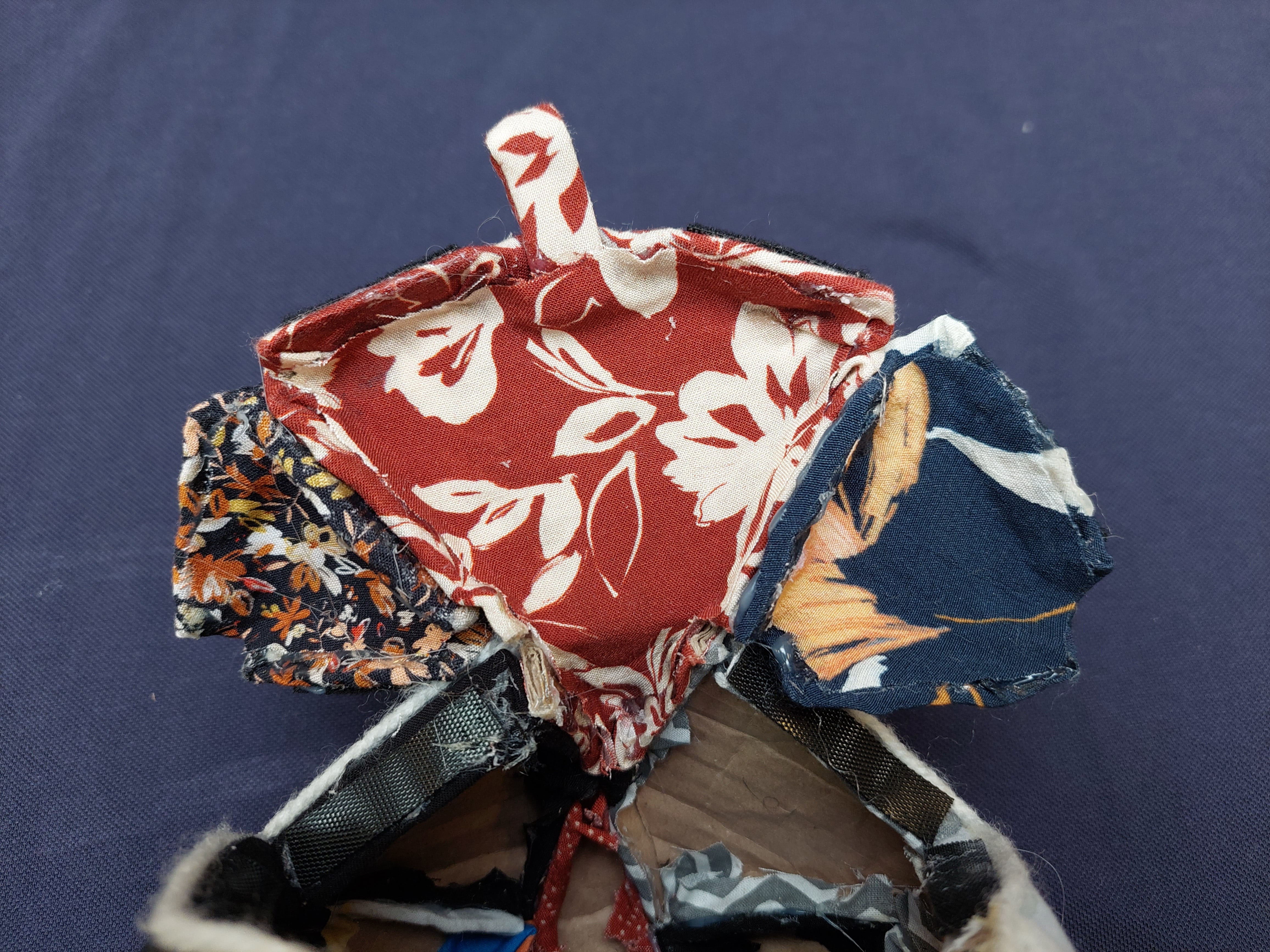
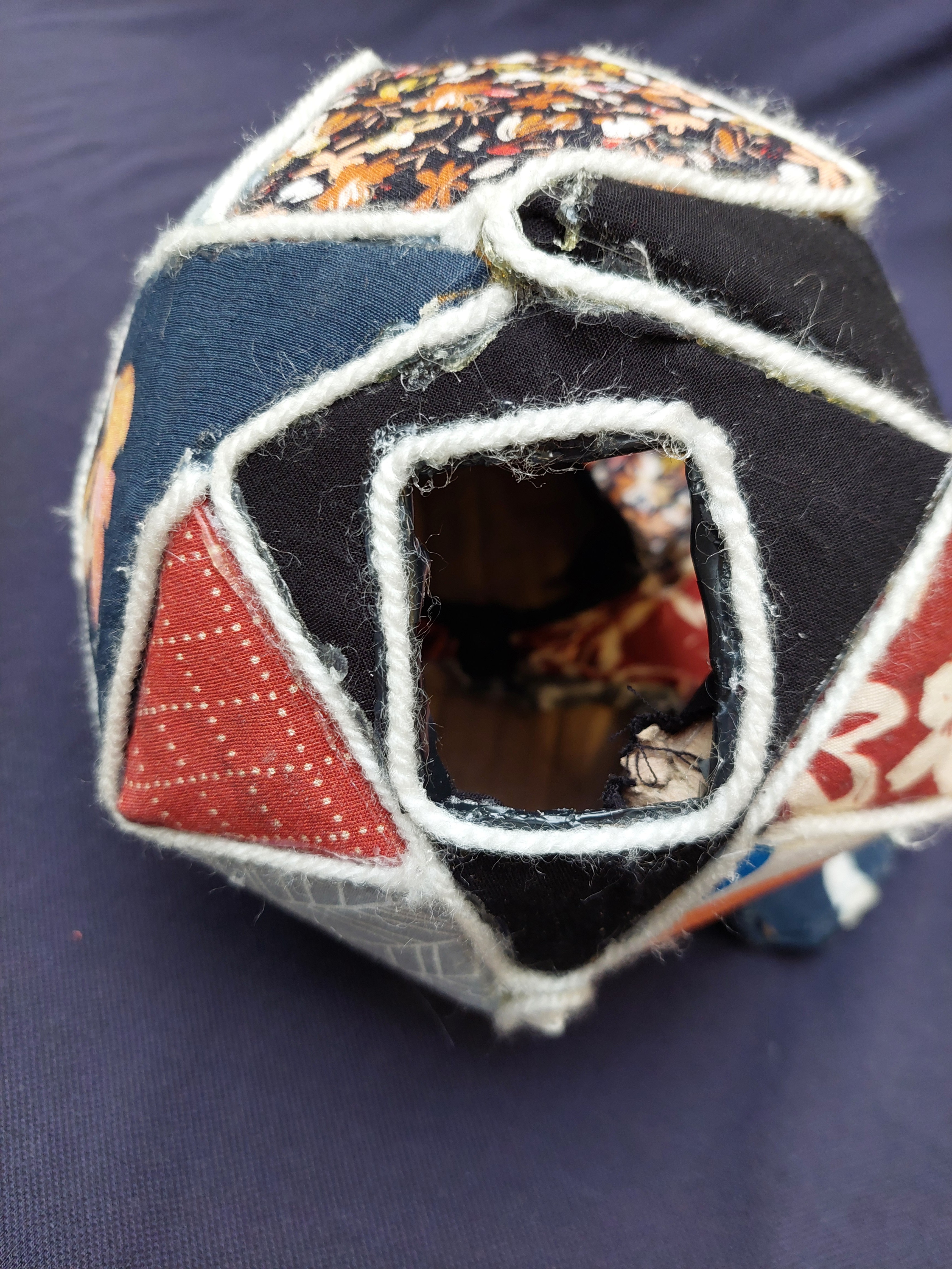
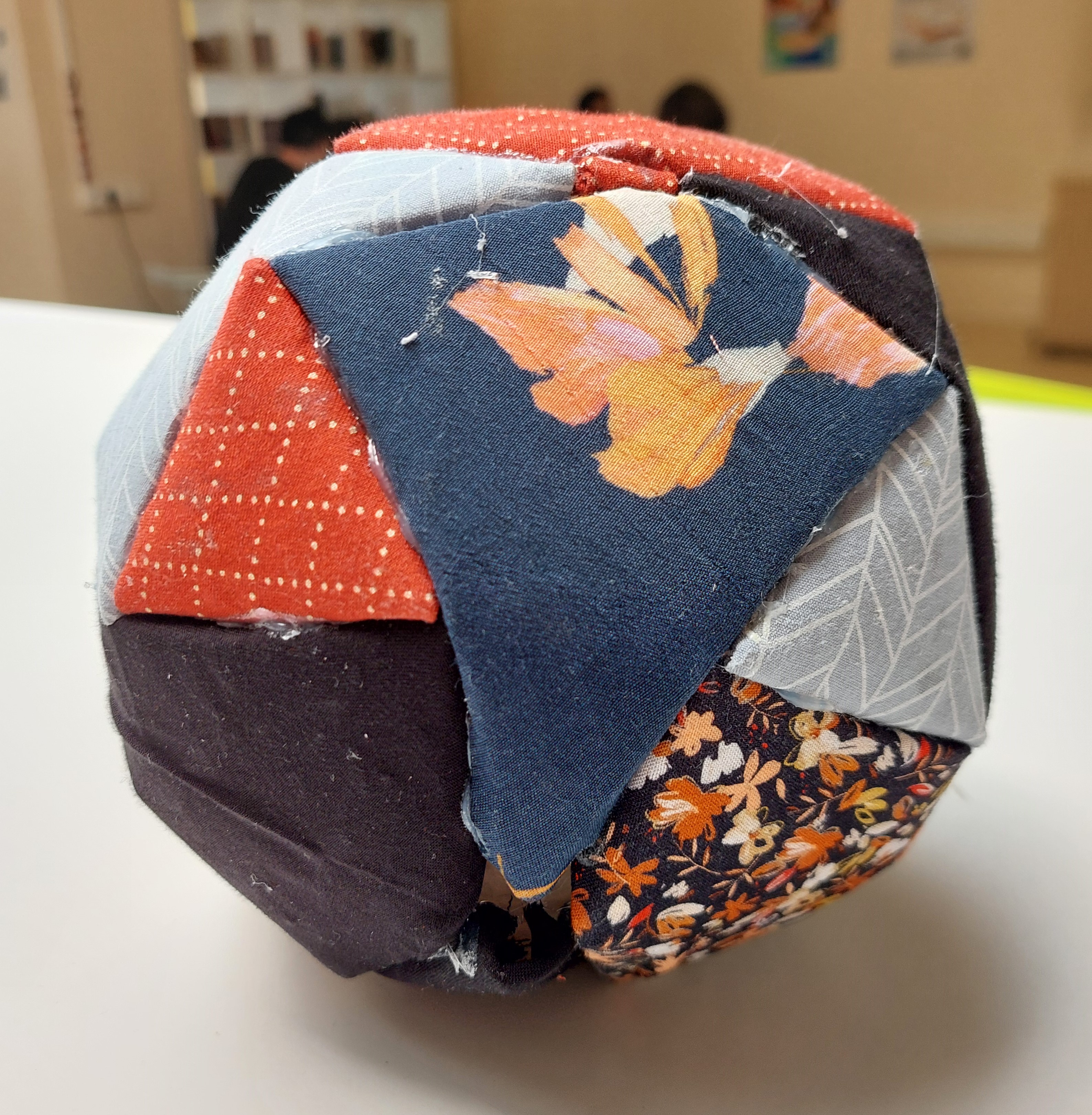
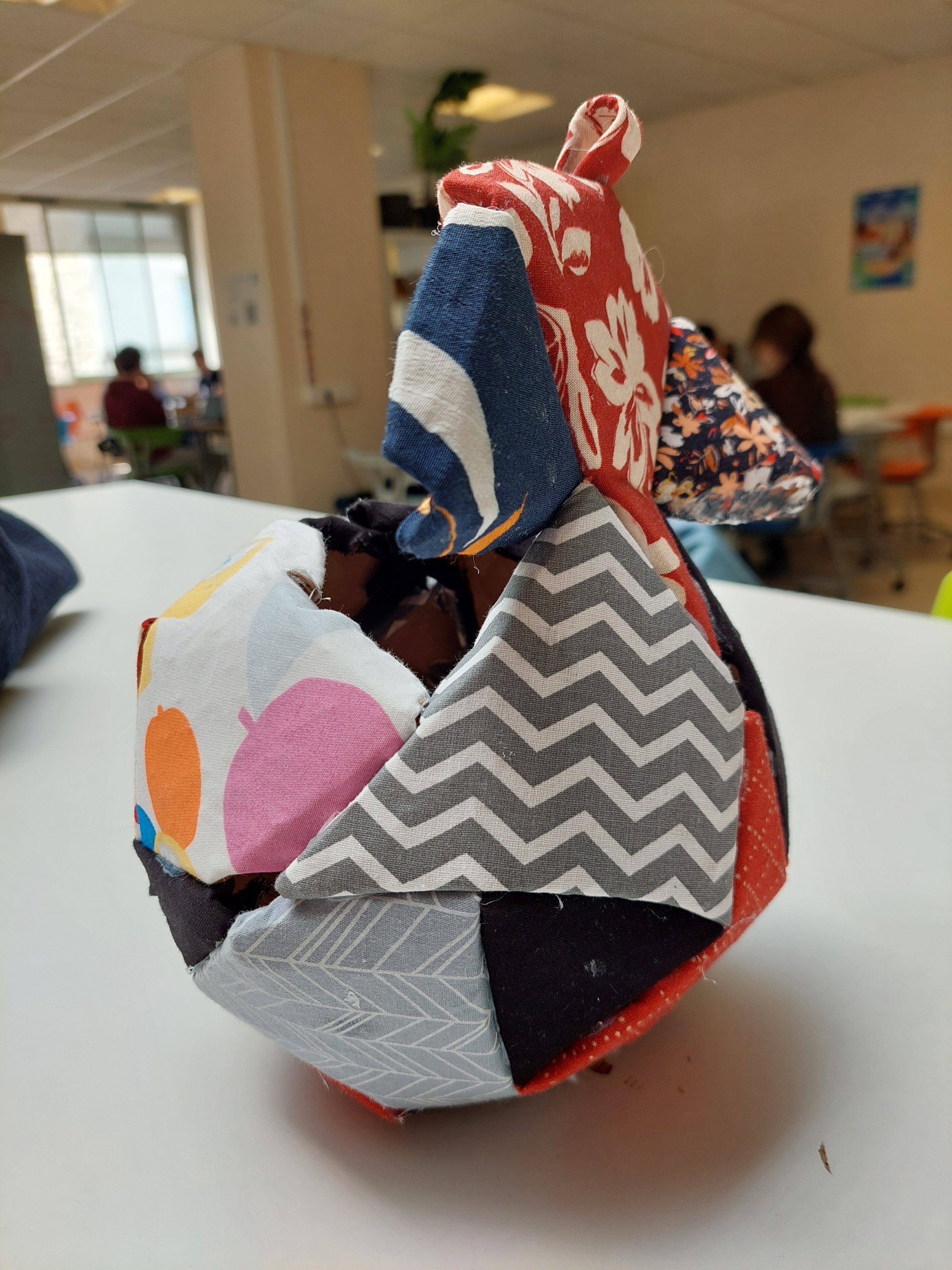
- polishing the opening of the ball so that the user doesn't see the cardboard right away
![]()
- cutting the hole for the screen and cleaning its edges
![]()
Finishing the book
We made a brand new book for a more finished look.
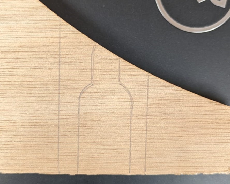
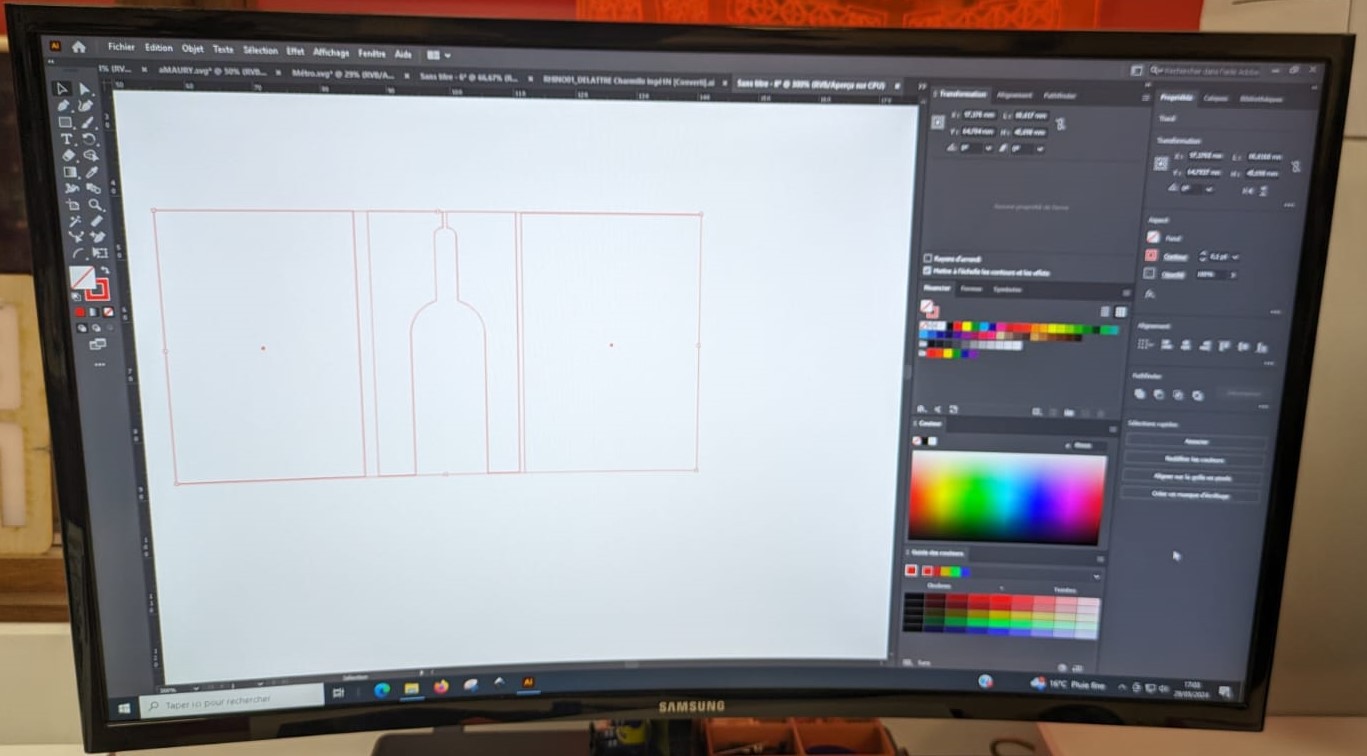
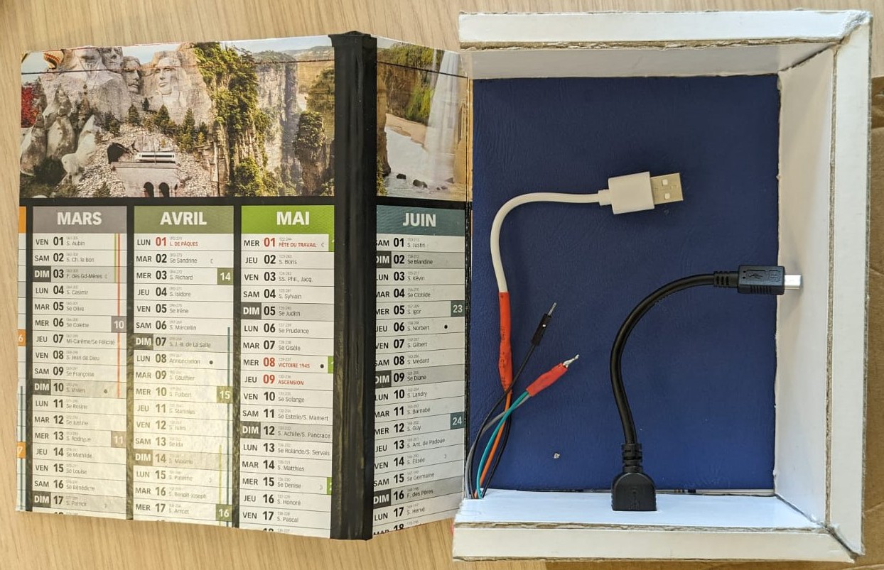
- support for the charging cable
![]()
![Schematics for the laser cutting of the support cable Schematics for the laser cutting of the support cable]()
![]()
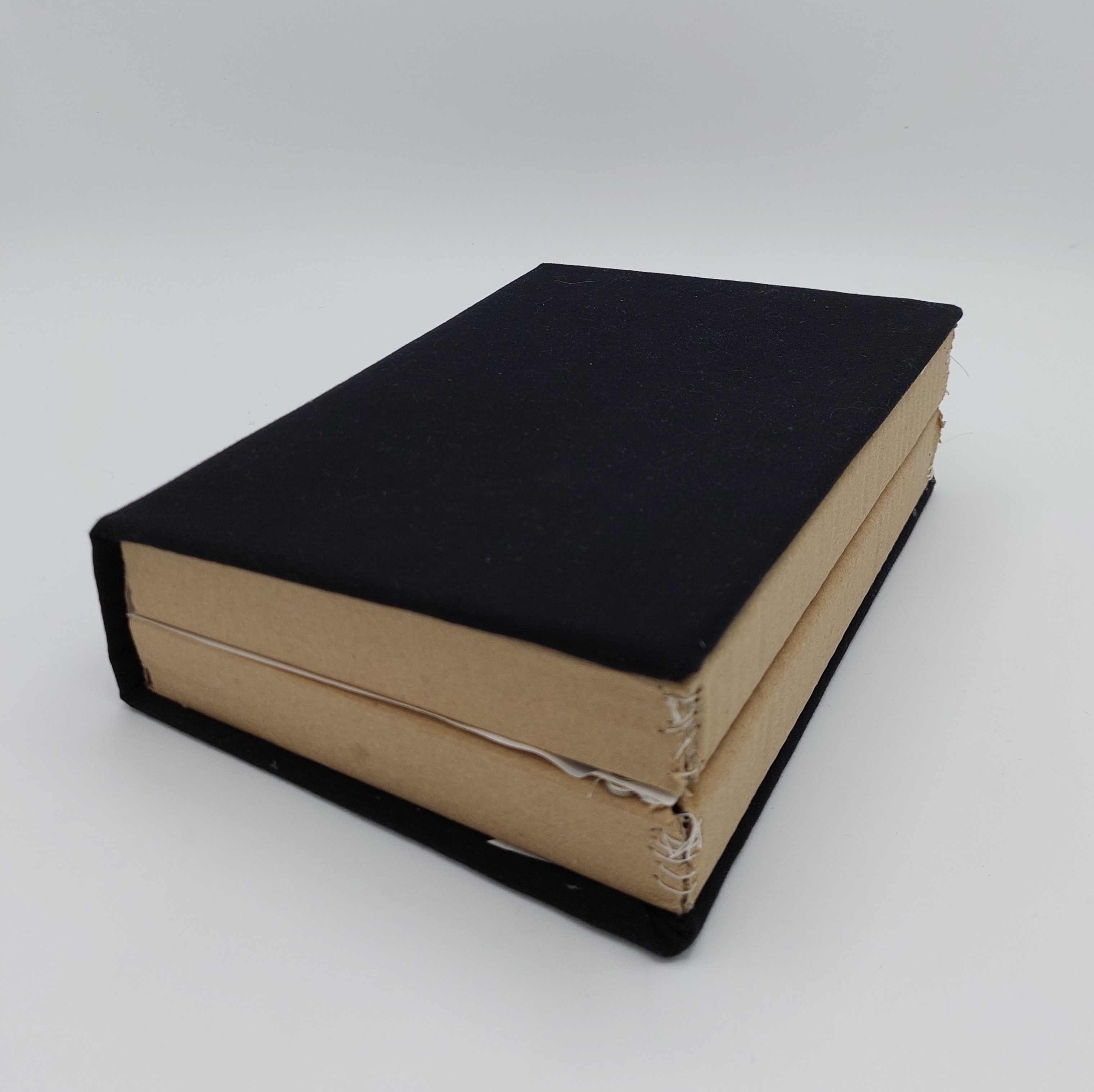
- the new cover
![]()
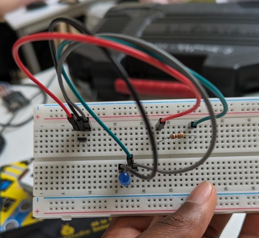
- the internal circuit of the book (so that it lights up automatically when it's opened)
![]()
- the cables to provide energy for the book to work
![]()
![]()
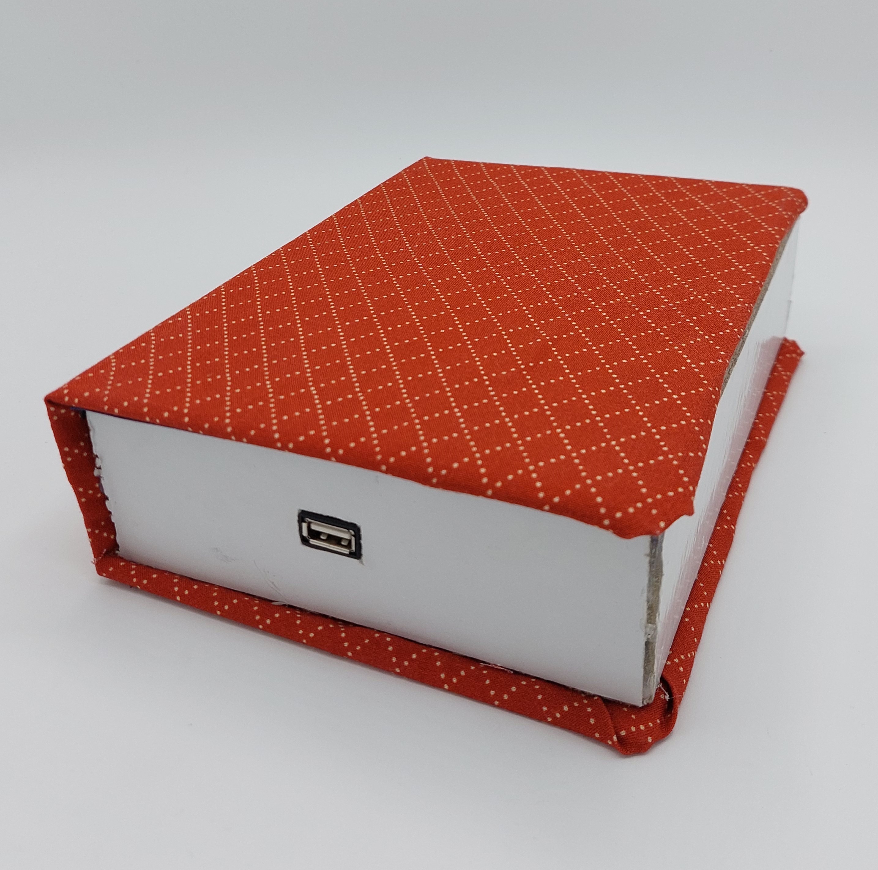
- finished product
BEFORE
![]()
![]()
AFTER
![]()
![]()
![]()
-
2024-05-5: encountering coding difficulties
05/28/2024 at 14:29 • 0 commentsOver the course of the last two weeks I struggled a lot with my arduino code.
First of all, arduino codes for an ESP32 + TFT screen or codes for ESP32 + gyroscope are practically inexistent. Most of them are designed for arduino uno.
Finding inspiration was hard...
First of all, I decided to use and old code which had been created so that when someone shakes the gyroscope, text appears on a 08x02 screen. It worked in that scenario so I thought that if I changed it for my RB-TFT1.8 screen, it would also work in this case.
What I didn't realise is that our images we wanted to display (instead of text like last semester), would have to be stored in the SD card of our screen... under bmp format.
So I changed all the images size on gimp so that they would fit perfeclty on our screen and converted them to the bmp format. I also learned that in order for our images to be displayed I would have to express their path in my code (eg: D:\Images\1.bmp)
Here are a few examples of codes I tried to modify for them to be adapted for my screen and ESP32:
Code for our screen + arduino Uno
// include TFT and SPI libraries
#include <TFT.h>
#include <SPI.h>

// pin definition for Arduino UNO
#define cs   10
#define dc   9
#define rst  8


// create an instance of the library
TFT TFTscreen = TFT(cs, dc, rst);

void setup() {

  //initialize the library
  TFTscreen.begin();

  // clear the screen with a black background
  TFTscreen.background(0, 0, 0);
  //set the text size
  TFTscreen.setTextSize(2);
}

void loop() {

  //generate a random color
  int redRandom = random(0, 255);
  int greenRandom = random (0, 255);
  int blueRandom = random (0, 255);

  // set a random font color
  TFTscreen.stroke(redRandom, greenRandom, blueRandom);

  // print Hello, World! in the middle of the screen
  TFTscreen.text("Hello, World!", 6, 57);

  // wait 200 miliseconds until change to next color
  delay(200);
}"
I tried adapting it for my ESP32:
#include <TFT_eSPI.h>
#include <SPI.h>


TFT_eSPI tft = TFT_eSPI();

void setup() {

  tft.init();


  tft.fillScreen(TFT_BLACK);


  tft.setTextSize(2);
}

void loop() {

  uint16_t color = tft.color565(random(0, 255), random(0, 255), random(0, 255));


  tft.setTextColor(color);


  tft.setCursor(20, 57);  // Adjust the cursor position as needed
  tft.print("Hello, World!");

  delay(200);
}
It didn't work and after multiple attempts I just gave up, and tried to see if it would work better if I tried to insert the gyroscope as well. And after multiple changes, different codes mashed together and altering the code each time I got an error message I finally got this code which didn't displayed any error messages when I clocked in the tick button:
#include <Wire.h>
#include <Adafruit_MPU6050.h>
#include <Adafruit_Sensor.h>
#include <SPI.h>
#include <SD.h>
#include <Adafruit_GFX.h>
#include <Adafruit_ST7735.h>


Adafruit_MPU6050 mpu;
const float shakeThreshold = 2.0;


#define TFT_CS     15
#define TFT_RST    2
#define TFT_DC     17
#define SD_CS      26
Adafruit_ST7735 tft = Adafruit_ST7735(TFT_CS, TFT_DC, TFT_RST);


const char* bmpFiles[] = {
  "1.bmp",
  "2.bmp",
  "3.bmp",
  "4.bmp",
  "5.bmp",
  "6.bmp",
  "7.bmp",
  "8.bmp",
  "9.bmp",
  "10.bmp",
  "11.bmp",
  "12.bmp"

};
const int bmpFileCount = sizeof(bmpFiles) / sizeof(bmpFiles[0]);

void setup() {
  Serial.begin(115200);


  if (!mpu.begin()) {
    Serial.println("Could not find a valid MPU6050 sensor, check wiring!");
    while (1);
  }
  Serial.println("MPU6050 Found!");
  mpu.setAccelerometerRange(MPU6050_RANGE_2_G);
  mpu.setGyroRange(MPU6050_RANGE_250_DEG);
  mpu.setFilterBandwidth(MPU6050_BAND_5_HZ);


  tft.initR(INITR_BLACKTAB);
  tft.fillScreen(ST7735_BLACK);


  if (!SD.begin(SD_CS)) {
    Serial.println("SD card initialization failed!");
    return;
  }
  Serial.println("SD card initialized.");
}


uint32_t read32(File &f) {
  uint32_t result;
  ((uint8_t *)&result)[0] = f.read();
  ((uint8_t *)&result)[1] = f.read();
  ((uint8_t *)&result)[2] = f.read();
  ((uint8_t *)&result)[3] = f.read();
  return result;
}

void loop() {
  sensors_event_t a, g, temp;
  mpu.getEvent(&a, &g, &temp);

  float magnitude = sqrt(a.acceleration.x * a.acceleration.x + a.acceleration.y * a.acceleration.y + a.acceleration.z * a.acceleration.z);

  if (magnitude > shakeThreshold) {
    Serial.println("Shake detected!");
    int randomIndex = random(0, bmpFileCount);
    displayBMP(bmpFiles[randomIndex], 0, 0);
    delay(1000);
  }

  delay(100);
}

void displayBMP(const char *filename, int16_t x, int16_t y) {
  File bmpFile;
  int bmpWidth, bmpHeight;
  uint8_t bmpDepth;
  uint32_t bmpImageoffset;
  uint32_t rowSize;
  uint8_t sdbuffer[3 * 20];
  uint8_t buffidx = sizeof(sdbuffer);
  boolean goodBmp = false;
  boolean flip = true;
  int w, h, row, col;
  uint8_t r, g, b;
  uint32_t pos = 0, startTime = millis();

  if ((x >= tft.width()) || (y >= tft.height())) return;

  Serial.println();
  Serial.print(F("Loading image '"));
  Serial.print(filename);
  Serial.println('\'');

  if ((bmpFile = SD.open(filename)) == NULL) {
    Serial.print(F("File not found"));
    return;
  }

  if (bmpFile.read() == 'B' && bmpFile.read() == 'M') {
    Serial.print(F("File size: ")); Serial.println(read32(bmpFile));
    (void)read32(bmpFile);
    bmpImageoffset = read32(bmpFile);
    Serial.print(F("Image Offset: ")); Serial.println(bmpImageoffset, DEC);

    Serial.print(F("Header size: ")); Serial.println(read32(bmpFile));
    bmpWidth  = read32(bmpFile);
    bmpHeight = read32(bmpFile);
    if (bmpFile.read() == 1) {
      bmpDepth = bmpFile.read();
      Serial.print(F("Bit Depth: ")); Serial.println(bmpDepth);
      if (bmpDepth == 24 && bmpFile.read() == 0) {
        goodBmp = true;
        Serial.print(F("Image size: "));
        Serial.print(bmpWidth);
        Serial.print('x');
        Serial.println(bmpHeight);

        rowSize = (bmpWidth * 3 + 3) & ~3;
        if (bmpHeight < 0) {
          bmpHeight = -bmpHeight;
          flip      = false;
        }

        w = bmpWidth;
        h = bmpHeight;
        if ((x + w - 1) >= tft.width())  w = tft.width()  - x;
        if ((y + h - 1) >= tft.height()) h = tft.height() - y;

        tft.setAddrWindow(x, y, x + w - 1, y + h - 1);

        for (row = 0; row < h; row++) {

          if (flip)
            pos = bmpImageoffset + (bmpHeight - 1 - row) * rowSize;
          else
            pos = bmpImageoffset + row * rowSize;
          if (bmpFile.position() != pos) {
            bmpFile.seek(pos);
            buffidx = sizeof(sdbuffer);
          }
          for (col = 0; col < w; col++) {
            // Time to read more pixel data?
            if (buffidx >= sizeof(sdbuffer)) { // Indeed
              bmpFile.read(sdbuffer, sizeof(sdbuffer));
              buffidx = 0;
            }

            b = sdbuffer[buffidx++];
            g = sdbuffer[buffidx++];
            r = sdbuffer[buffidx++];
            tft.pushColor(tft.color565(r, g, b));
          }
        }
        Serial.println(F("Loaded image"));
      }
    }
  }

  bmpFile.close();
}
But my problem is that when I try to upload it the the ESP32, I get this error message:
A fatal error occurred: Packet content transfer stopped (received 8 bytes).
I tried to check my ESP32 pins, I tried to check my wirering, I changed ESP32 and I even changed cables. But this error message keeps appearing.
-
2024-05-28
05/28/2024 at 14:04 • 0 commentsBall
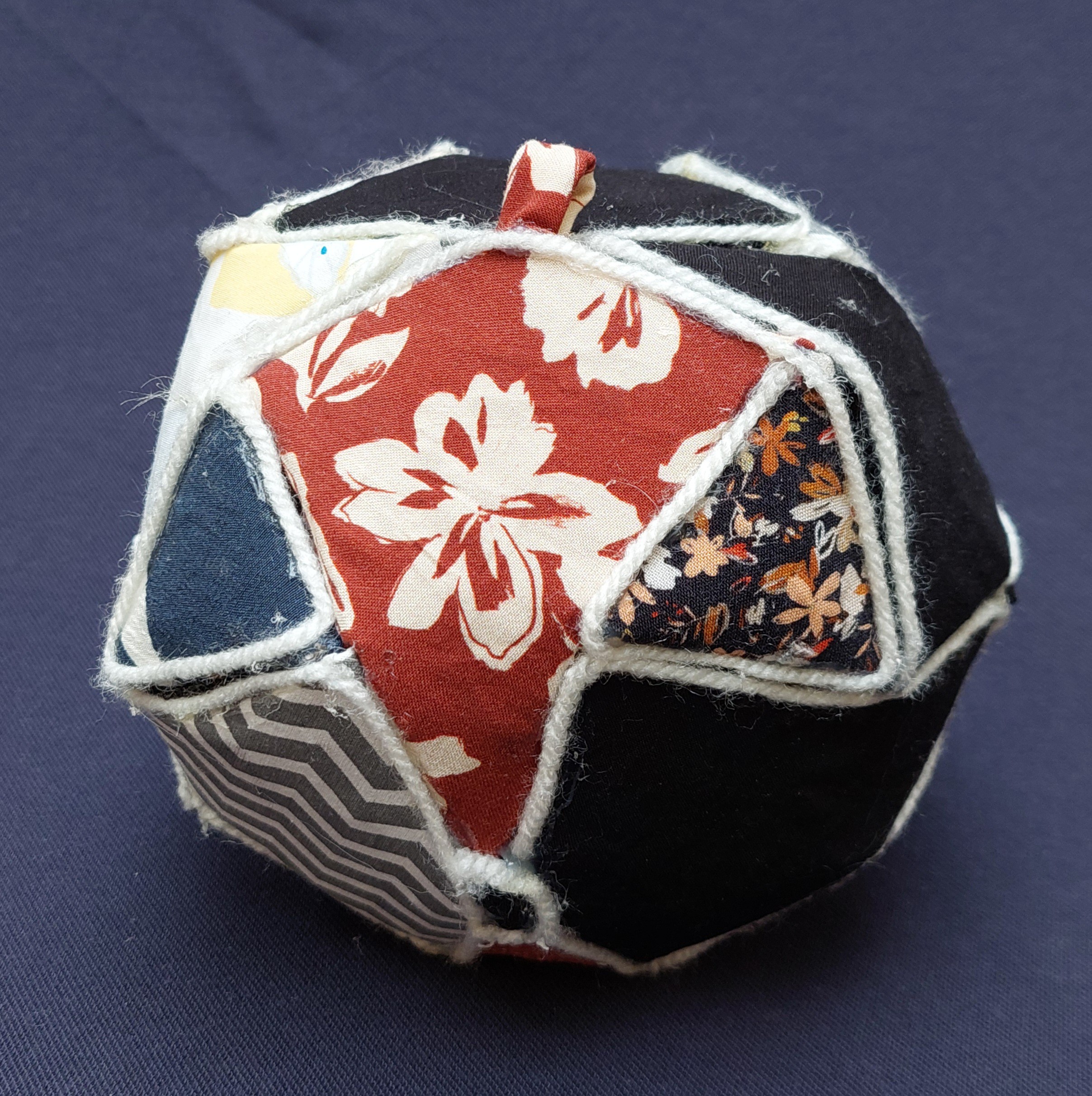
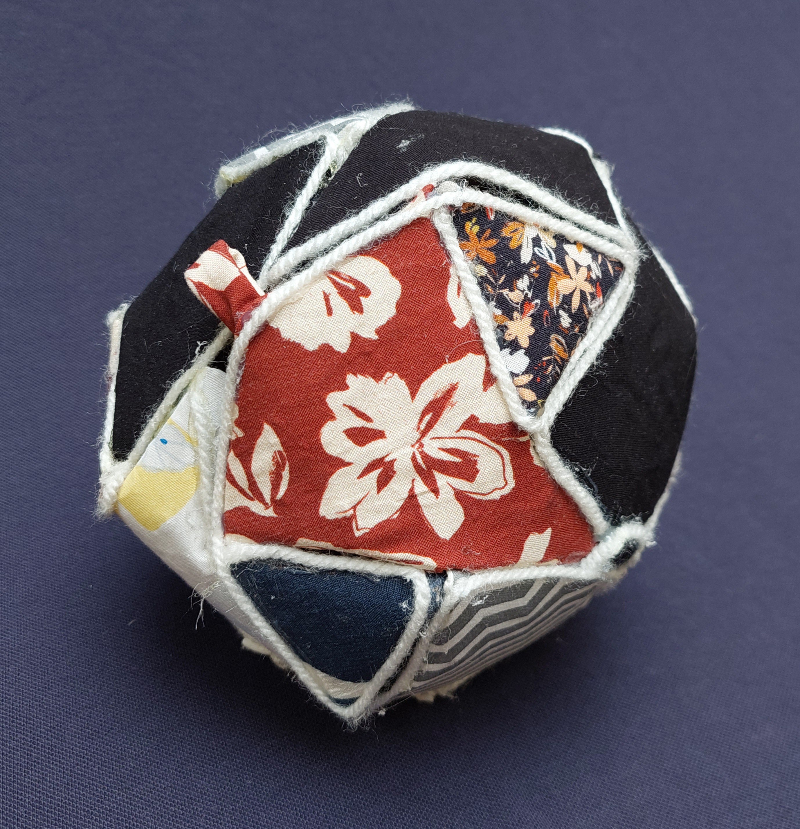
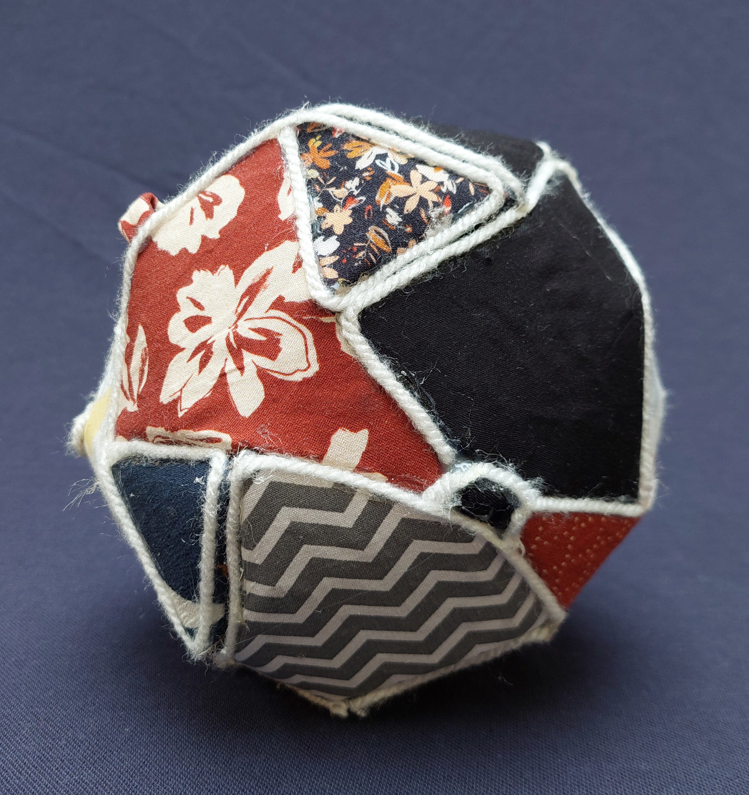
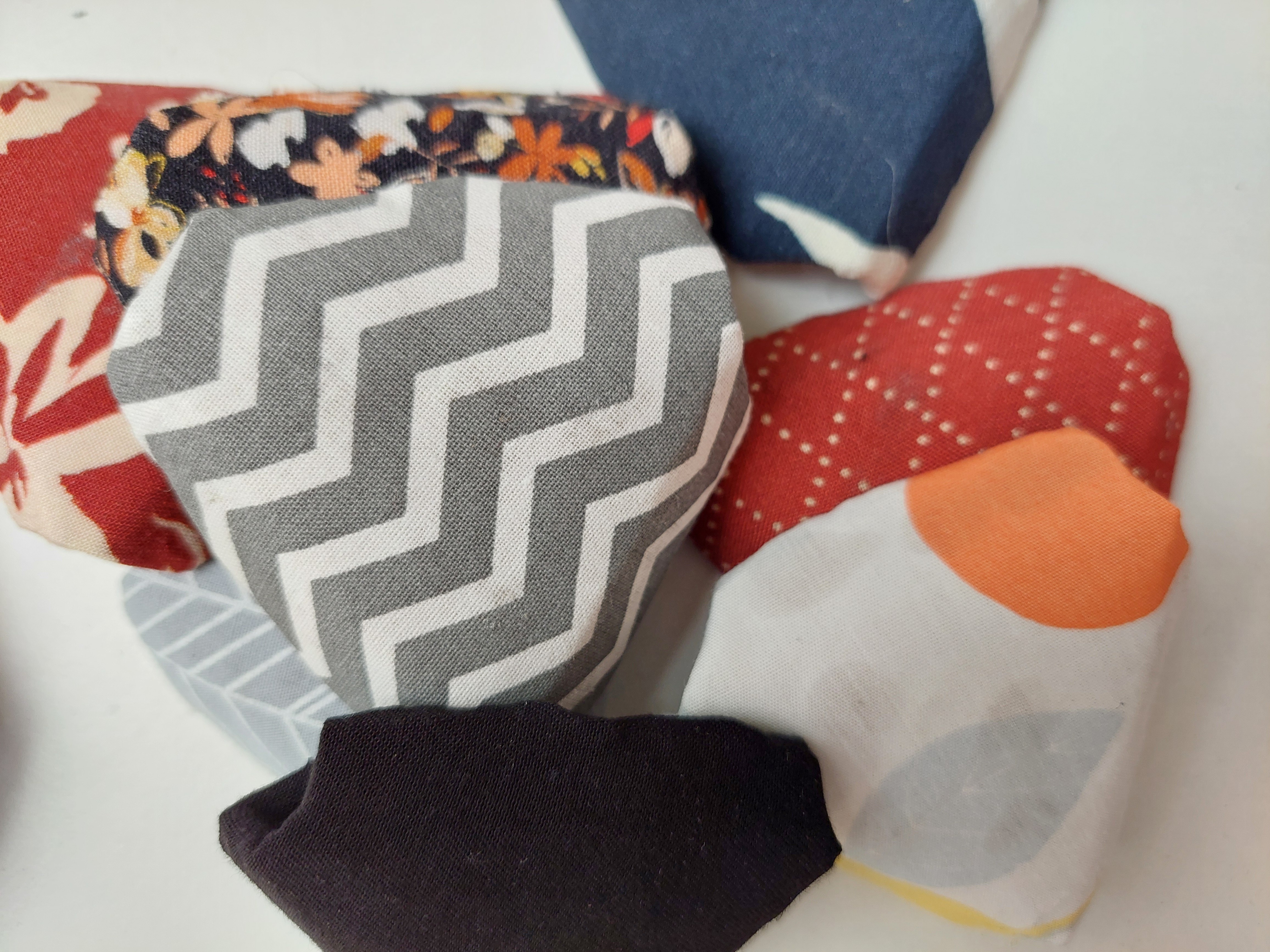
Today, we finished the ball.
![]()
![]()
![]()
Book
We assembled the book structure, soldered the circuit and it works.
-
2024-05-02
05/28/2024 at 13:57 • 0 commentsGetting familiar with the screen and the gyroscope
The screen has arrived, and I started to familiarise myself with it's features.
I checked it's datasheet and rewied the gyroscopes features as well. Most of the time the way it's supposed to be wired is only indicated for an arduino uno, so I also have to check the pins of my ESP32 in order to understand how to wire my system.
Helpful website for the screen:
ESP32: TFT Touchscreen - 2.8 inch ILI9341 (Arduino) | Random Nerd Tutorials
Helpful website for ESP32 and screen:
Exploiter 1,8 pouce TFT sur ESP-32 Dev Kit C (az-delivery.de)
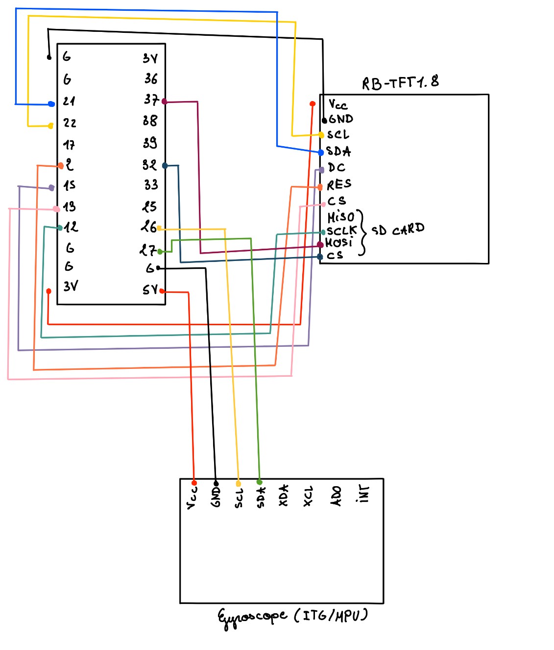
Pins:
Gyroscope:
- Gyroscope VCC to ESP32 3V pin.
- Gyroscope GND to any GND pin on the ESP32.
- Gyroscope SCL to pin 12, 13, 25, 26, or 27 on the ESP32 (choose one of these available GPIO pins).
- Gyroscope SDA to pin 12, 13, 25, 26, or 27 on the ESP32 (choose a different pin than the one used for SCL).
ESP32 and RB-TFT1.8 Screen
- Power Connections:
- VCC to 3V on the ESP32.
- GND to any G
- I2C Connections (for SCL and SDA):
- SCL to Pin 22
- SDA to Pin 21
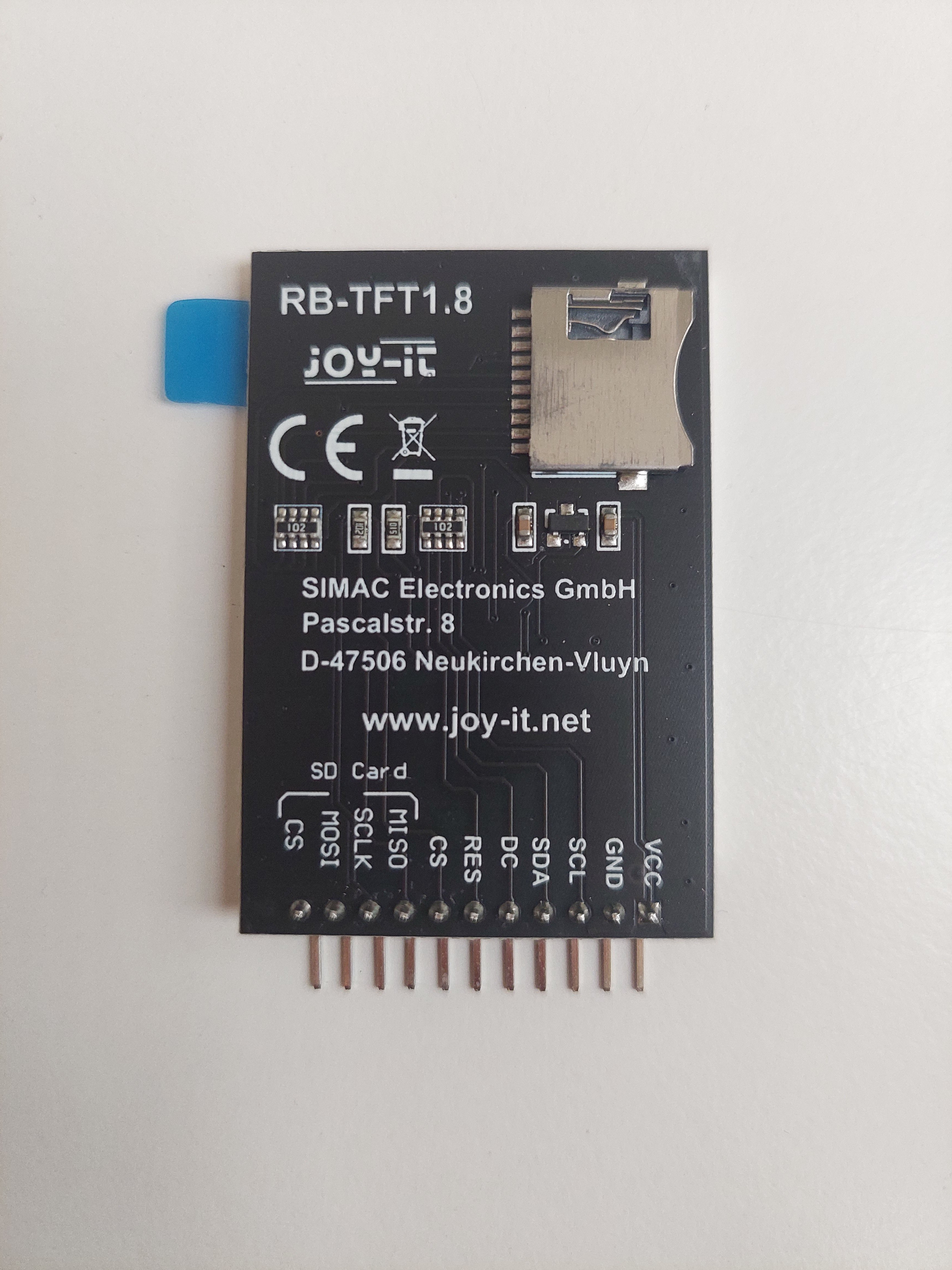
- SPI Connections (for the screen and SD card):
- DC to Pin 17
- RES (Reset) to Pin 2
- CS to Pin 15
- MISO to Pin 32
- SCLK to Pin 33
- MOSI to Pin 25
- CS to Pin 26
Schematic:
![]()
-
2024-05-23
05/23/2024 at 09:32 • 0 commentsInstruction Book
I have received valuable answers from the forums :
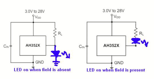
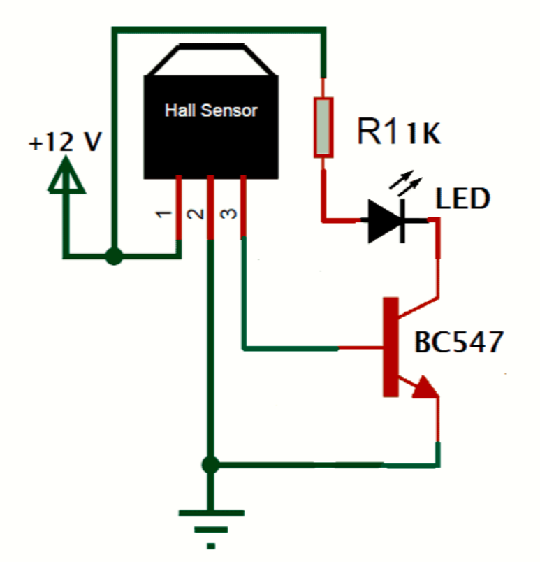
Here is the answer I needed. Figures the only issue I had was the placement of the LED, there is no need for a transistor.
more details here: https://forum.allaboutcircuits.com/threads/trying-to-invert-a-hall-effect-sensor-with-led.200980/
SO, I have obviously tried the circuit and it works as intended !
see file "Hall effect LED - demo 1"
Ball
We managed to put the whole ball together.
![]()
![]()
![]()
![]()
-
2024-05-21
05/21/2024 at 15:09 • 0 commentsInstruction Book
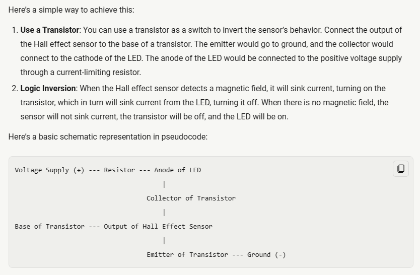
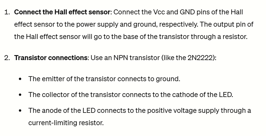
Inverting the Hall effect sensor
I tried several options some of them listed here:
- http://denethor.wlu.ca/pc300/projects/sensors/hallbook.pdf
- Copilot suggestion
![]()
- Chat GPT suggestion
![]()
But most of them don't work or make the LED switched on no matter what. Whether the magnet is here or not only changes the intensity of the LED.
And I think I have burnt my transistor in the process...
Next try will be this :
found on this website : https://how2electronics.com/hall-effect-sensor-a3144-magnetic-switch/
![]()
I have asked on forums, so I am waiting for answers there too
-
2024-05-16
05/16/2024 at 10:59 • 0 commentsBall
More tests for DF Player
- "get started" example from the "DFRobotDFPlayerMini.h" library
- this one :
- more from : DFPlayer Mini Mp3 Player - DFRobot Wiki
- and several other tries from random YouTube videos I found
But this was not conclusive.
So I moved to the subject of the Hall effect sensor.
Instruction BookHall effect sensor
The sensor we ordered is : 3524405C (AH3524)
the objective is for a LED to turn on when the magnet is far/not here, and turn off when the magnet is very close.
However, the sensor we ordered has the reverse effect: The LED turns on when the magnet is close to the sensor. Similar to the first example shown in this video :
2 Basic Project with Hall effect Sensor (youtube.com)
So the solution we found is to use a NPN transistor.
Quest to find the transistor : just started.
Ball
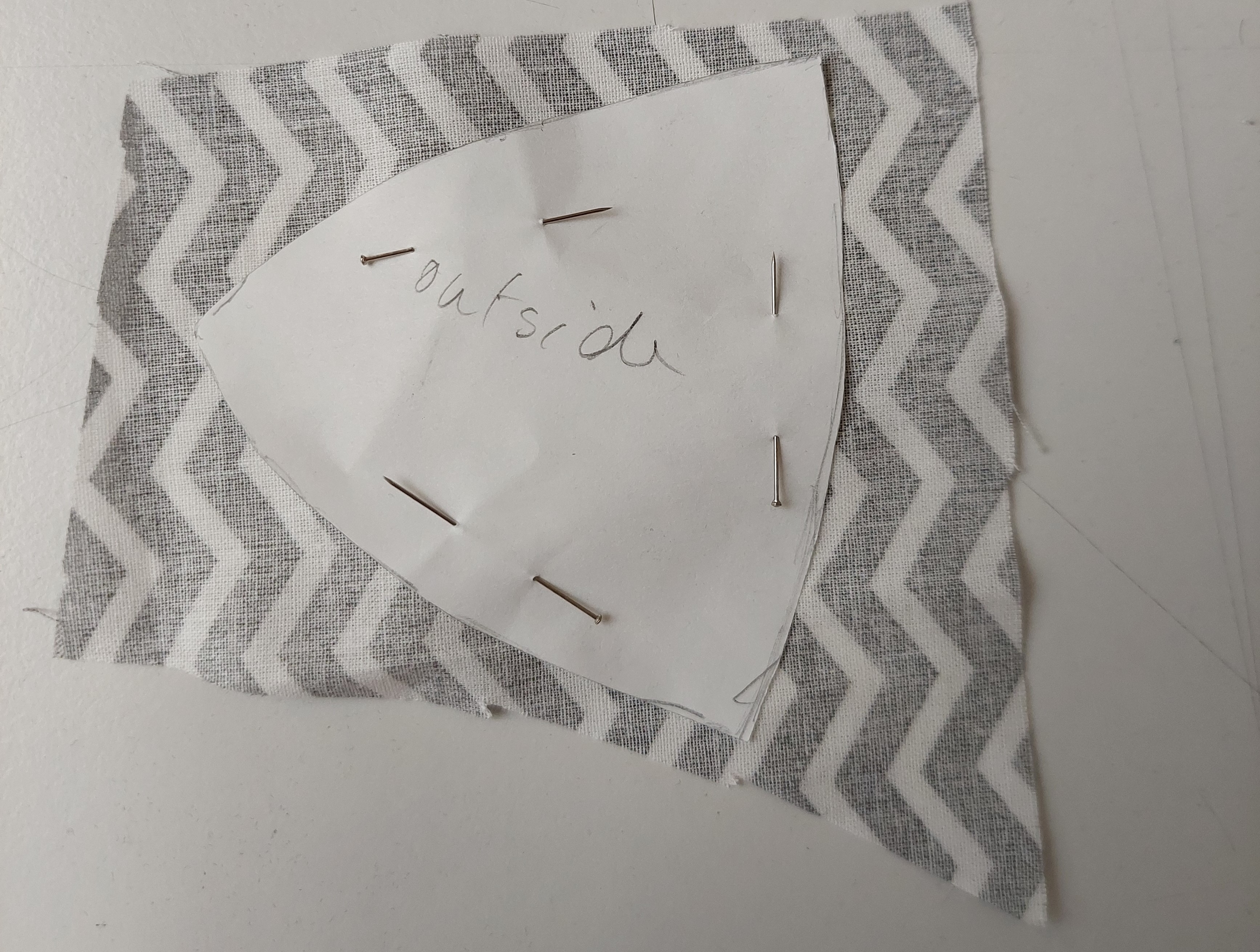
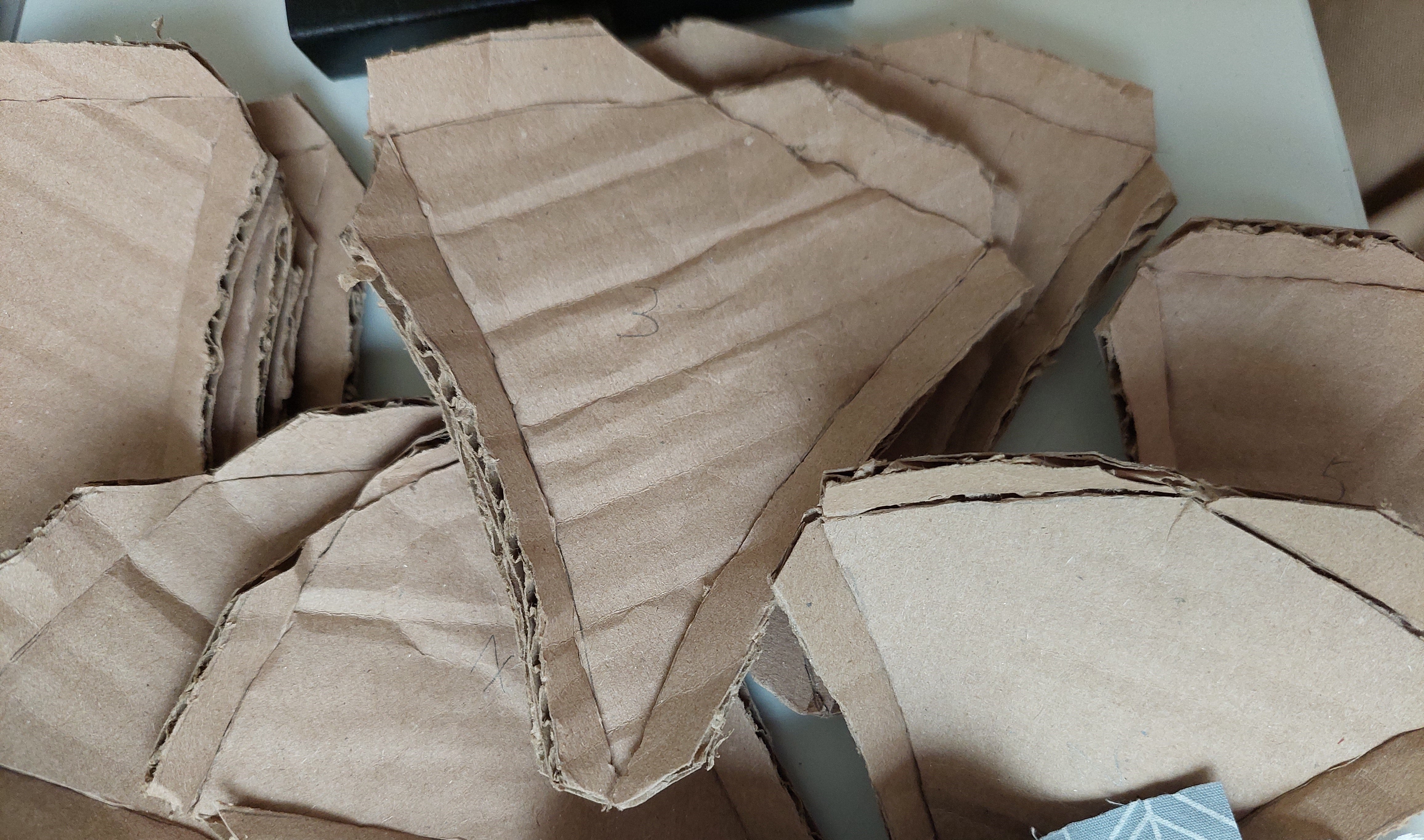
We also worked on the ball itself, preparing the patreons and cutting the pieces in the cardboard.
The goal is to cover each piece of carbon with a piece of fabric and put them all together like the paper prototype.
We also planned to have a "door" to open the ball.
![]()
-
2024-05-02
05/02/2024 at 11:30 • 0 commentsBall
More tests for DF Player
Today we tried to solve the issue we had last week to make the DFplayer work with the ESP32:
following this tutorial : (8650) DFPlayer Mini Interface with ESP32: Audio Playback Tutorial | Add voice to ESP32 - YouTube
here is the code from the video:
#include "SoftwareSerial.h"
#include "DFRobotDFPlayerMini.h"

// Use pins 2 and 3 to communicate with DFPlayer Mini
static const uint8_t PIN_MP3_TX = 25; // Connects to module's RX
static const uint8_t PIN_MP3_RX = 27; // Connects to module's TX
SoftwareSerial softwareSerial(PIN_MP3_RX, PIN_MP3_TX);

// Create the Player object
DFRobotDFPlayerMini player;

void setup() {

  // Init USB serial port for debugging
  Serial.begin(9600);
  // Init serial port for DFPlayer Mini
  softwareSerial.begin(9600);

  // Start communication with DFPlayer Mini
  if (player.begin(softwareSerial)) {
   Serial.println("OK");

    // Set volume to maximum (0 to 30).
    player.volume(20);
    // Play the first MP3 file on the SD card
    player.play(1);
  } else {
    Serial.println("Connecting to DFPlayer Mini failed!");
  }
}

void loop() {


   }
However, I get an error message :
I tried another code I found in the comments:
#include "DFRobotDFPlayerMini.h"

DFRobotDFPlayerMini player; // Create the Player object

void setup() {

  Serial.begin(9600); // Init USB serial port for debugging

  Serial2.begin(9600); // Init serial port for DFPlayer Mini

  // Start communication with DFPlayer Mini

  Serial.println("Connecting to DFplayer");

  while (!player.begin(Serial2))

  {

      Serial.print(".");

      delay(1000);

  }

  Serial.println(" DFplayer connected!");

  player.volume(20); // Set volume to maximum (0 to 30).

}


void loop() {

    player.play(1);

    delay(3000);

    player.play(2);

    delay(3000);

    player.play(3);

    delay(3000);

   }
but I get the same error message.
SO, I tried another code from another source :
#include <DFPlayer_Mini_Mp3.h>


#include <SoftwareSerial.h>

#include <DFRobotDFPlayerMini.h>


SoftwareSerial mySerial(25, 27); // RX, TX

void setup() {
    mySerial.begin(9600);
    mp3_set_serial(mySerial);
    mp3_set_volume(15);       // fixe le son (30 maximum)
    mp3_set_EQ(0);            // equalizer de 0 Ã 5
}

void loop() {
    mp3_play();  // joue mp3/0001.mp3
    delay(5000); // pause de 5 secondes

}
and another one:
#include <SoftwareSerial.h>
#include <DFPlayer_Mini_Mp3.h>

SoftwareSerial mySerial(25, 27); // RX, TX

//
void setup () {
  Serial.begin (9600);
  mySerial.begin (9600);
  mp3_set_serial (mySerial);  //set softwareSerial for DFPlayer-mini mp3 module
  mp3_set_volume (15);
}


//
void loop () {
  mp3_play (1);
  delay (6000);
  mp3_next ();
  delay (6000);
}
However, the libraries involved might only work for Arduino and give this type of error message with the ESP32:
Then, I tried reinstalling the libraries, re-setting up the ESP32, and did all the updates.
But nothing works I still get this error message:
DEBRIEF :
I still have the same error message, the ESP32 set-up does not seem faulty, the last 2 libraries don't work for ESP32, something is still not clear in the first 2 codes
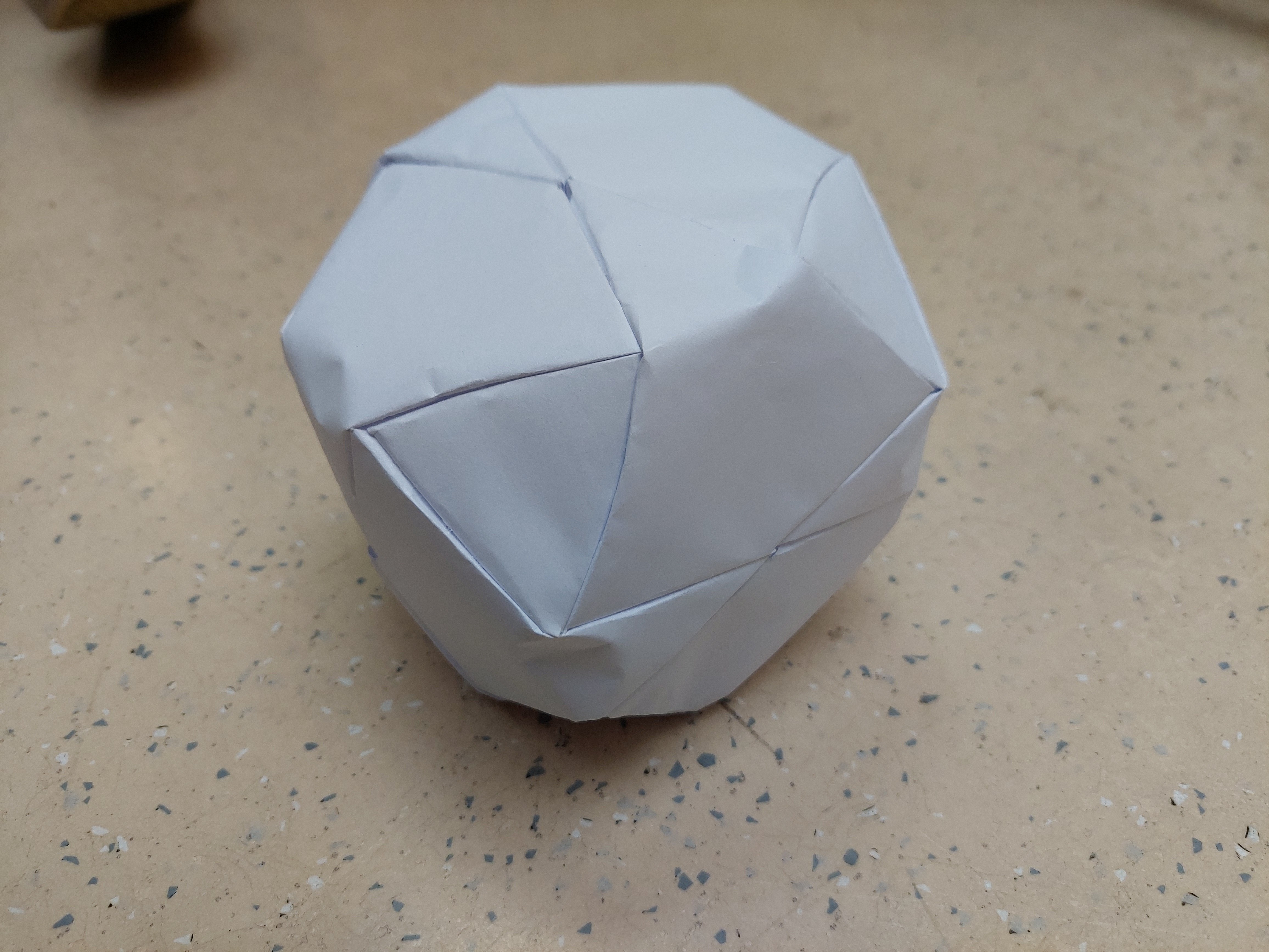
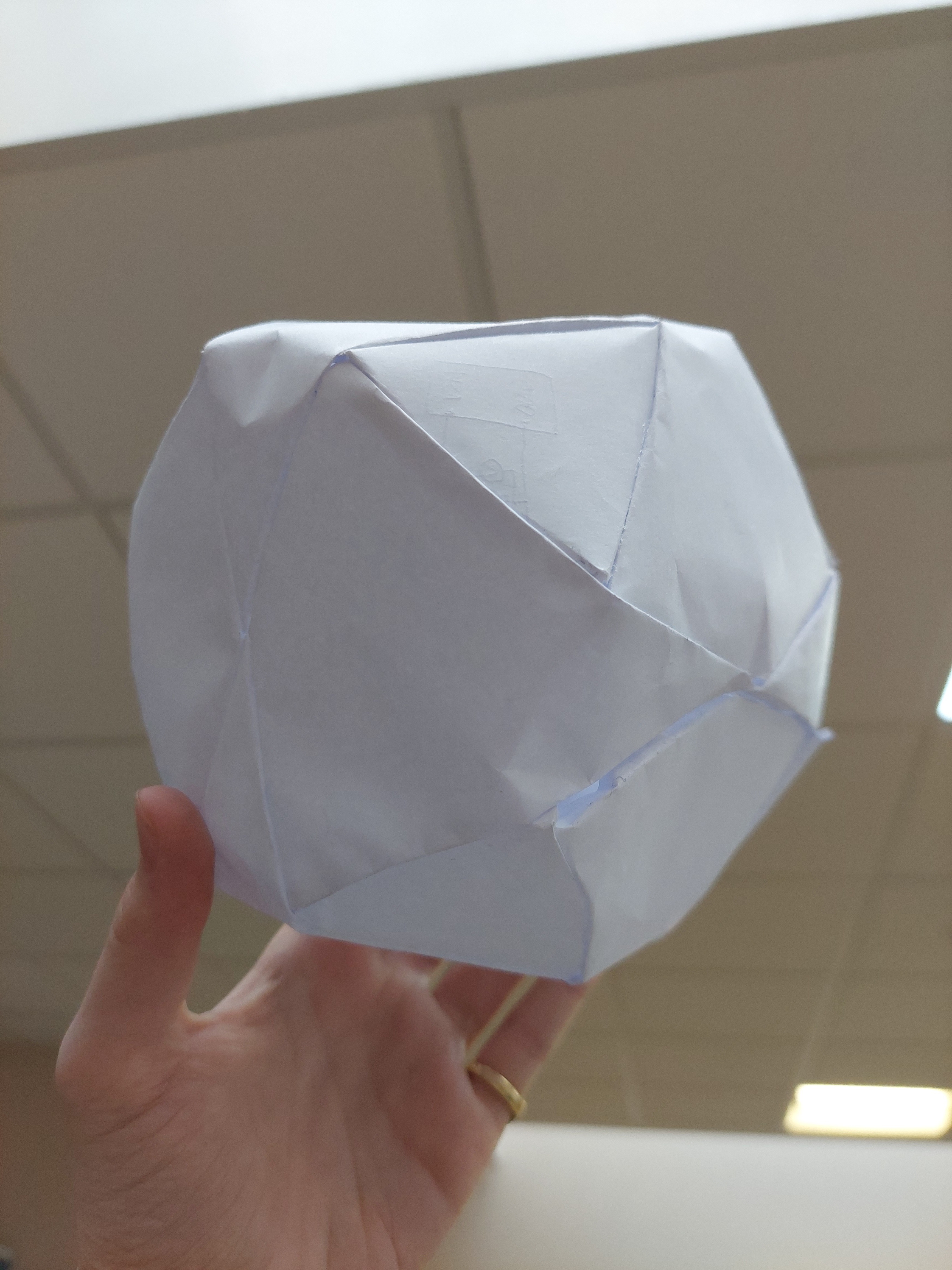
BallWe also worked on the design of the ball and made a paper prototype to make sure that the dimensions are right and the ball would be nice looking.
![]()
![]()
![]()
![]()
We are still hesitating about the final material we'll use for the final version (either leather or cardboard with fabric covering it).
-
2024-04-24
04/25/2024 at 09:08 • 0 commentsDelivery
Today, we received our whole order:
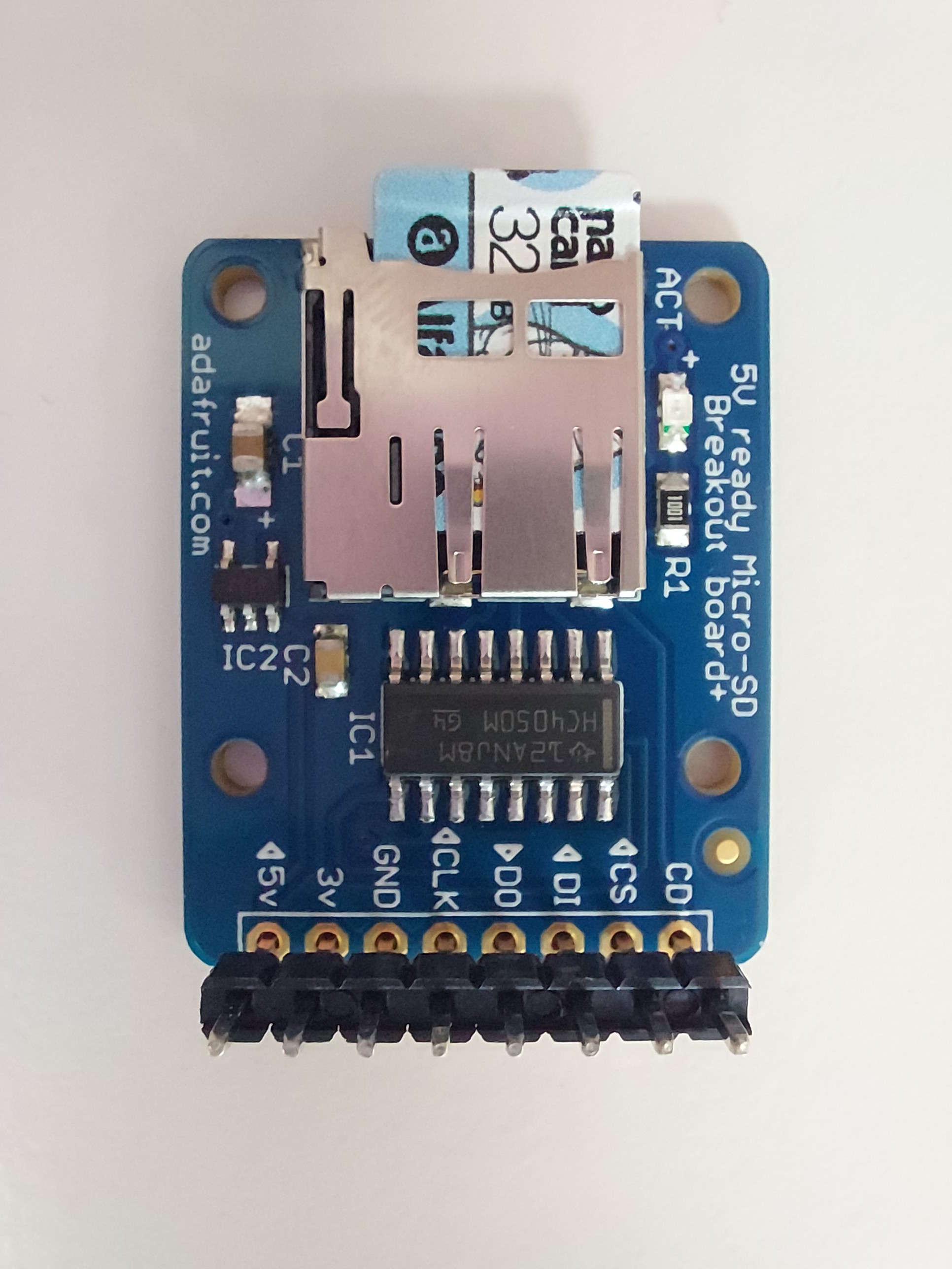
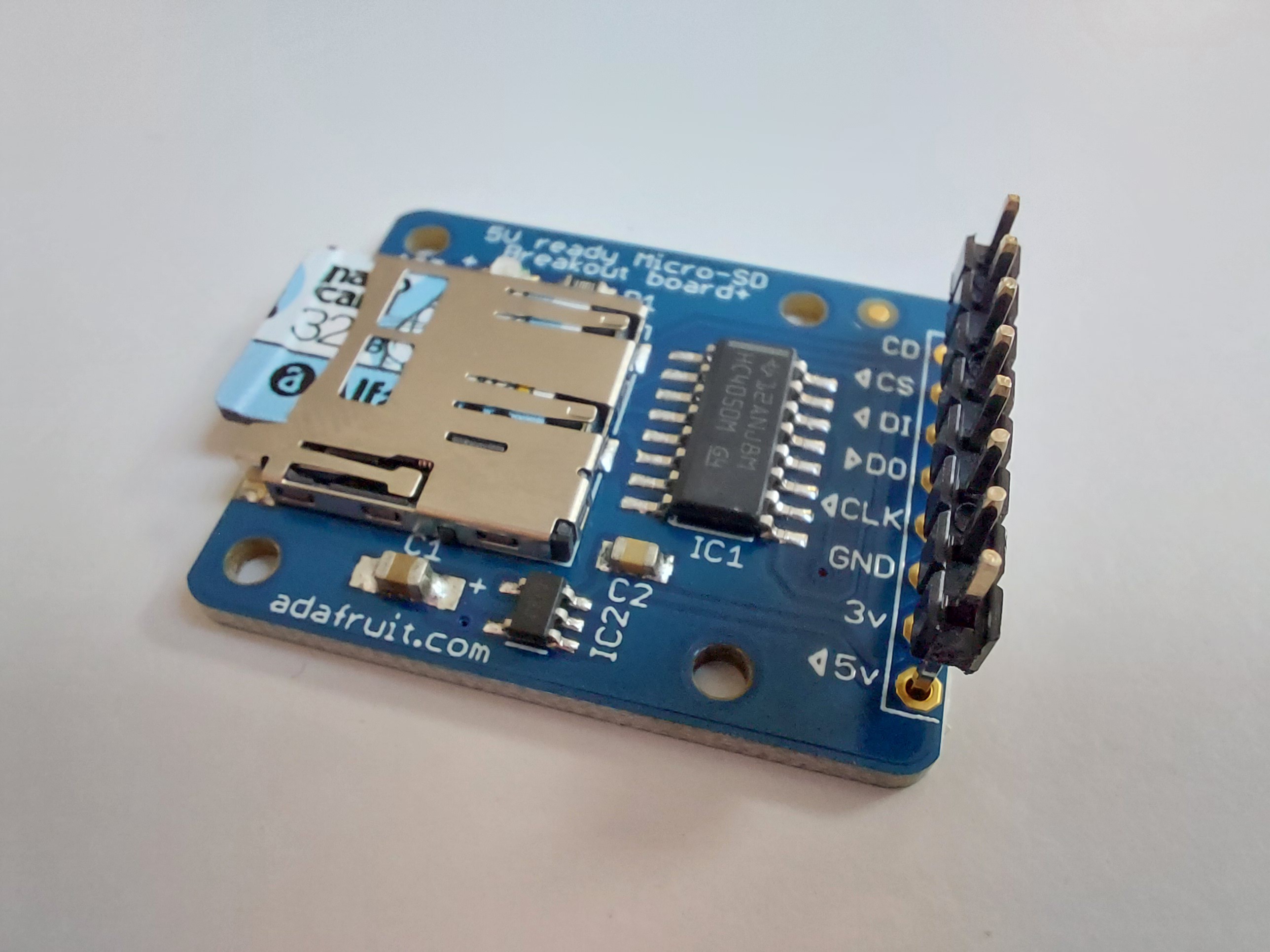
- micro-SD module card ADA254:
![]()
![]()
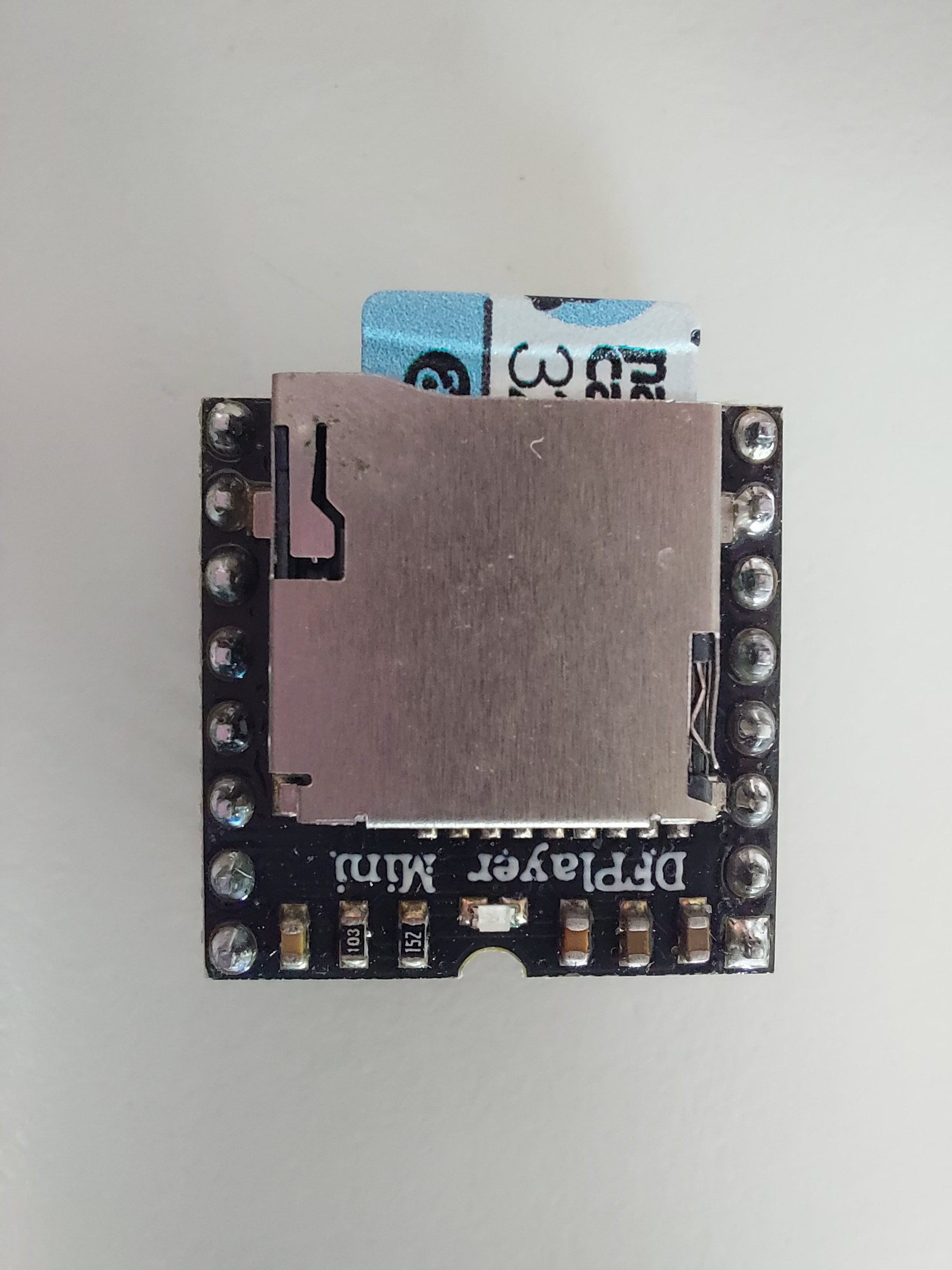
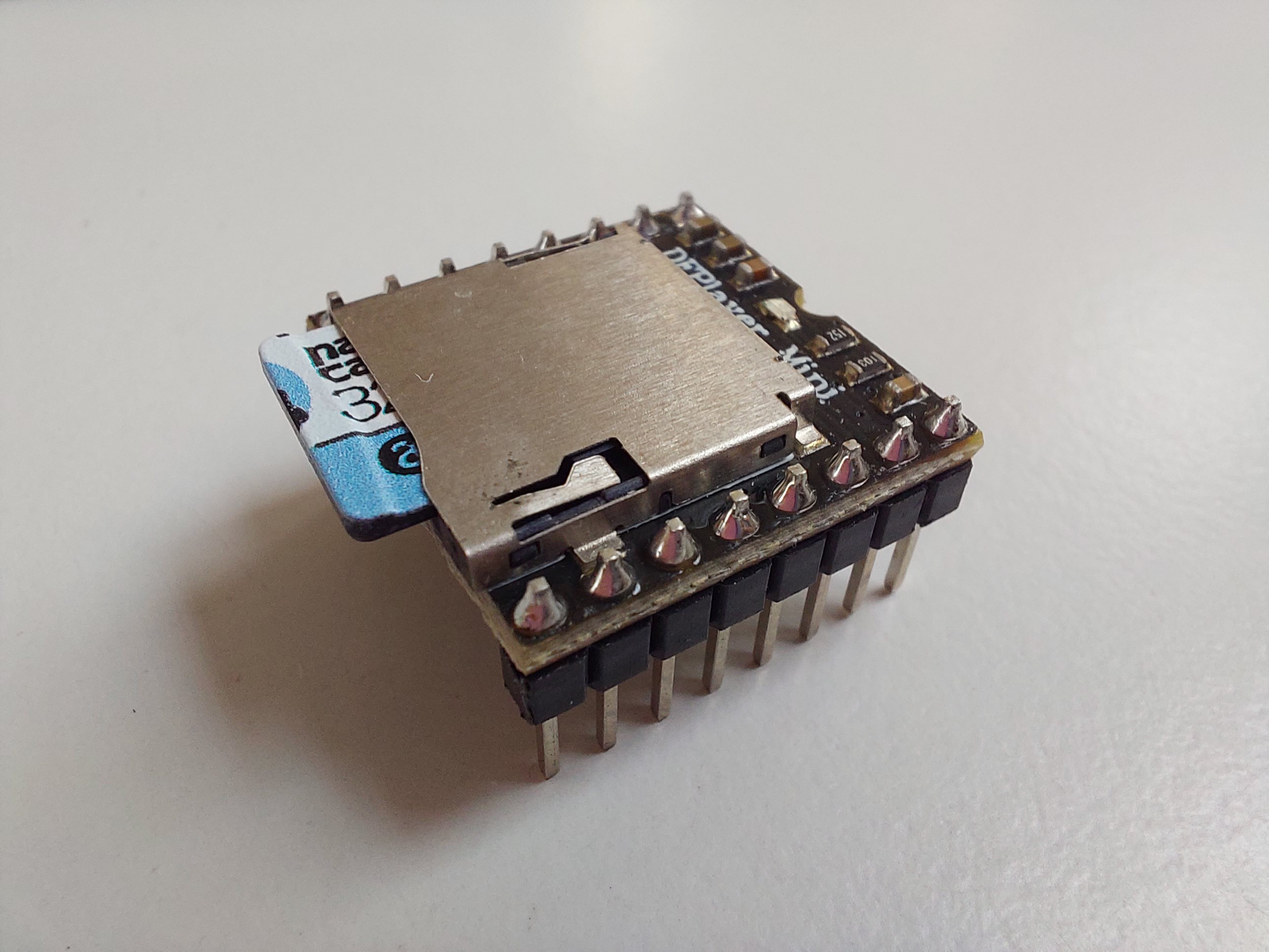
- audio amplifier module MP3 DF player:
![]()
![]()
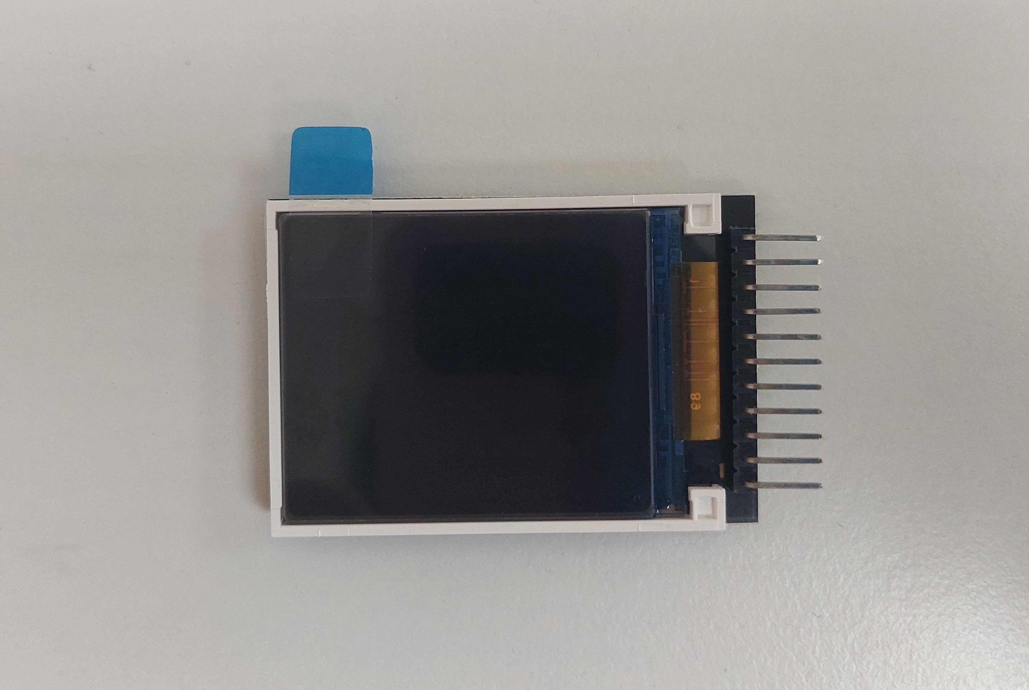
- RB-TFT1.8 1,8'' screen:
![]()
![]()
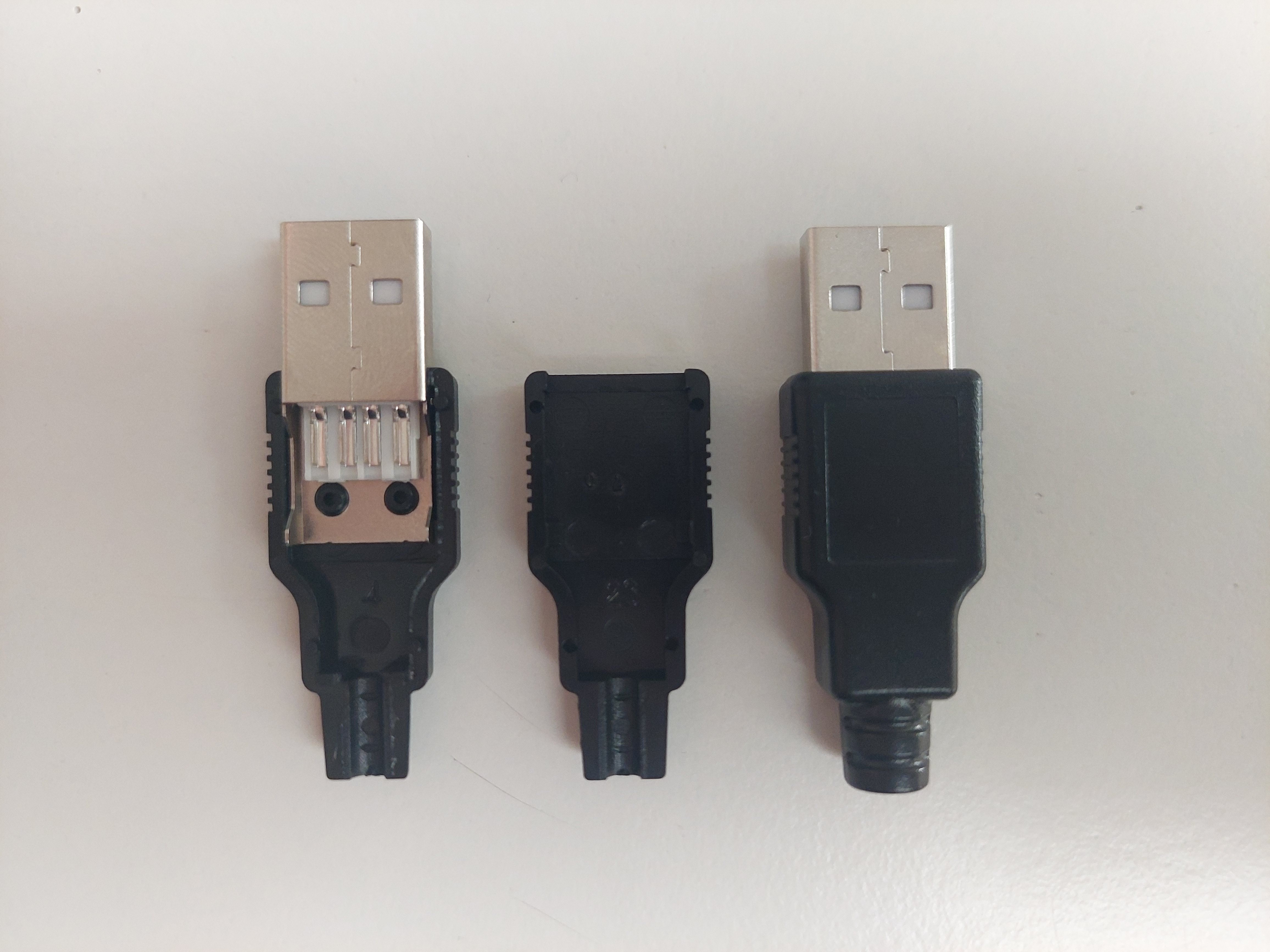
- USB cable male/male:
![]()
We decided not to order the cable so that we could create our own, with the voltage and length desired.
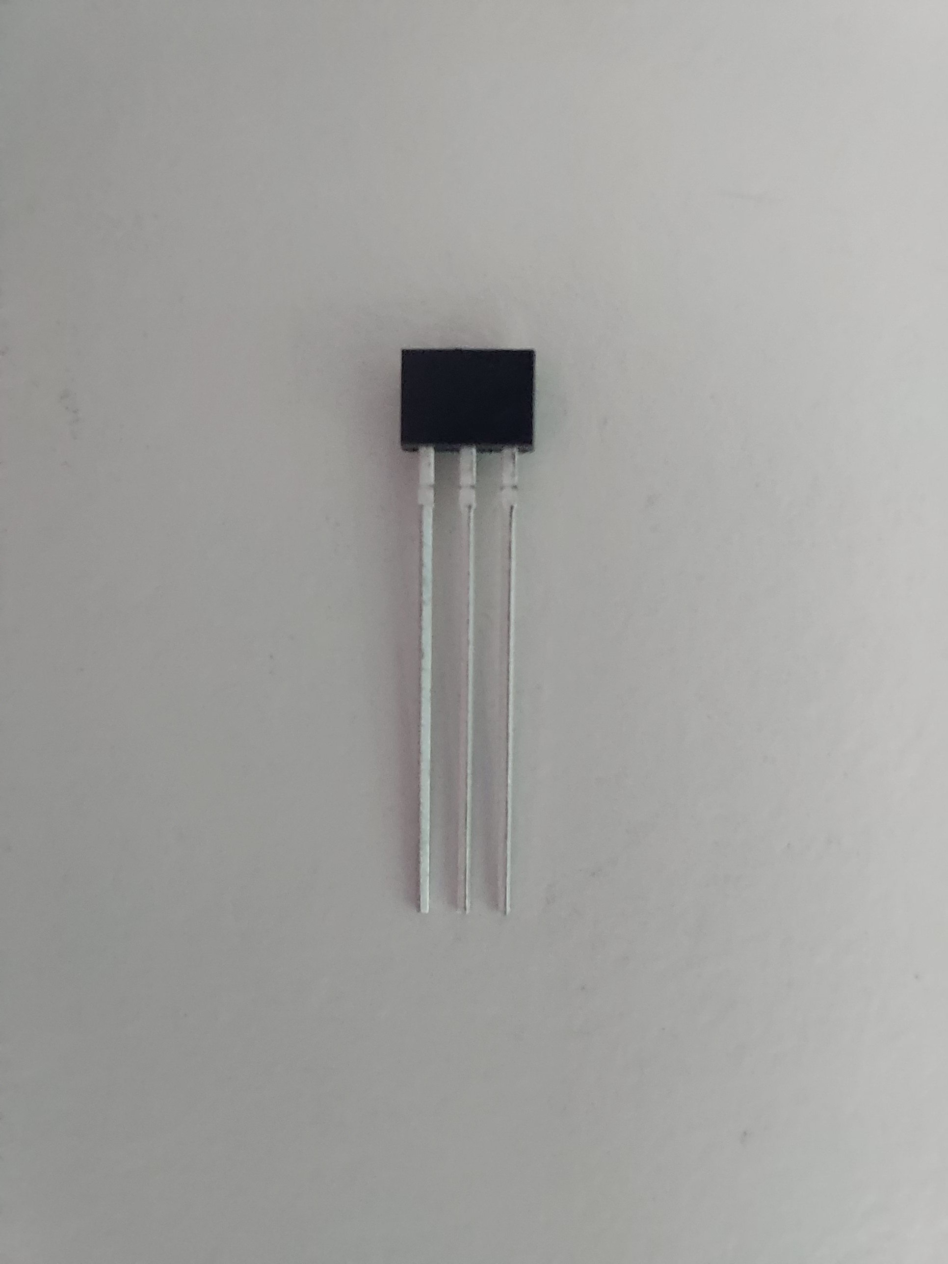
- hall effect magnetic sensor:
![]()
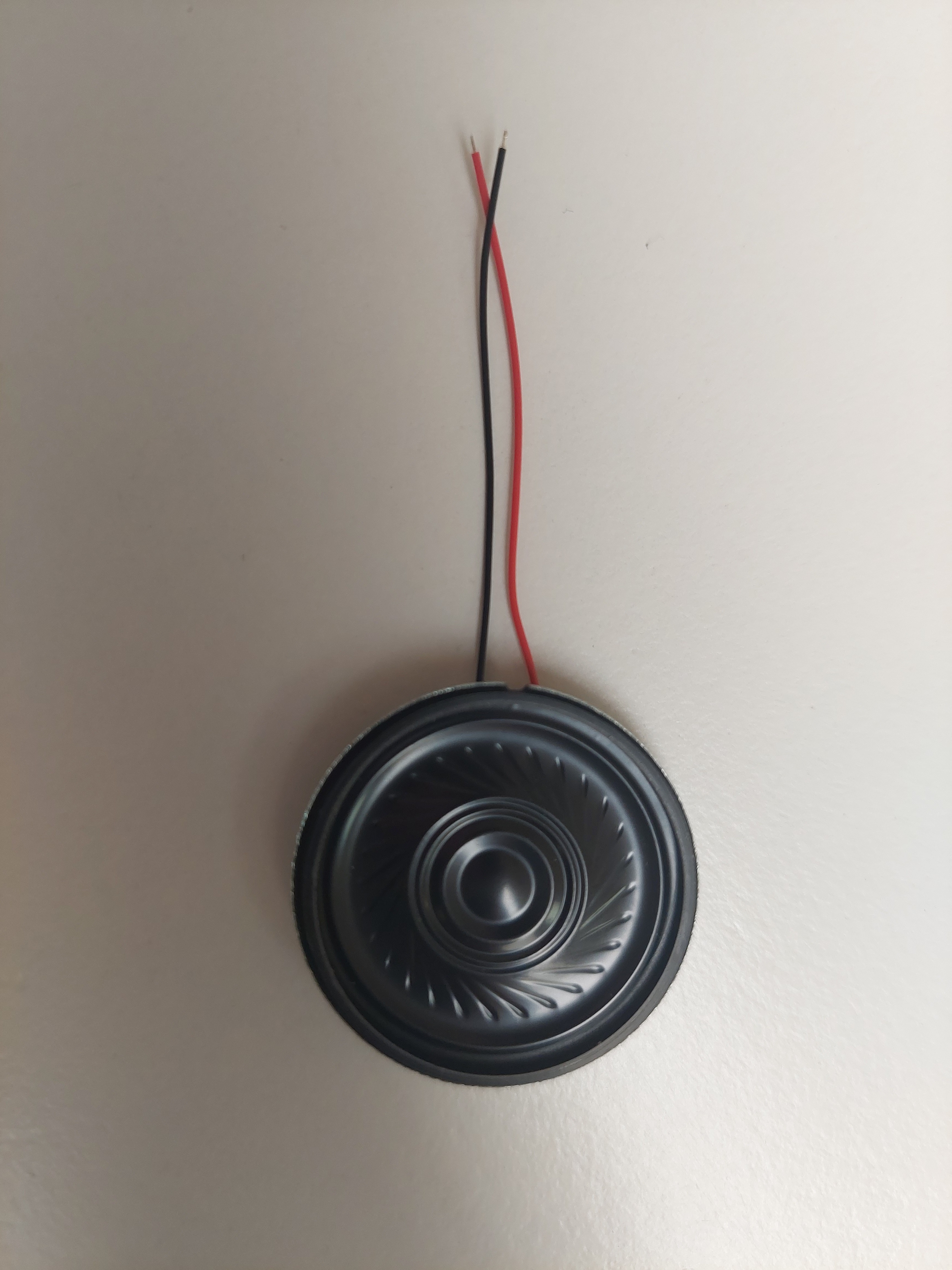
- mini speaker:
![]()
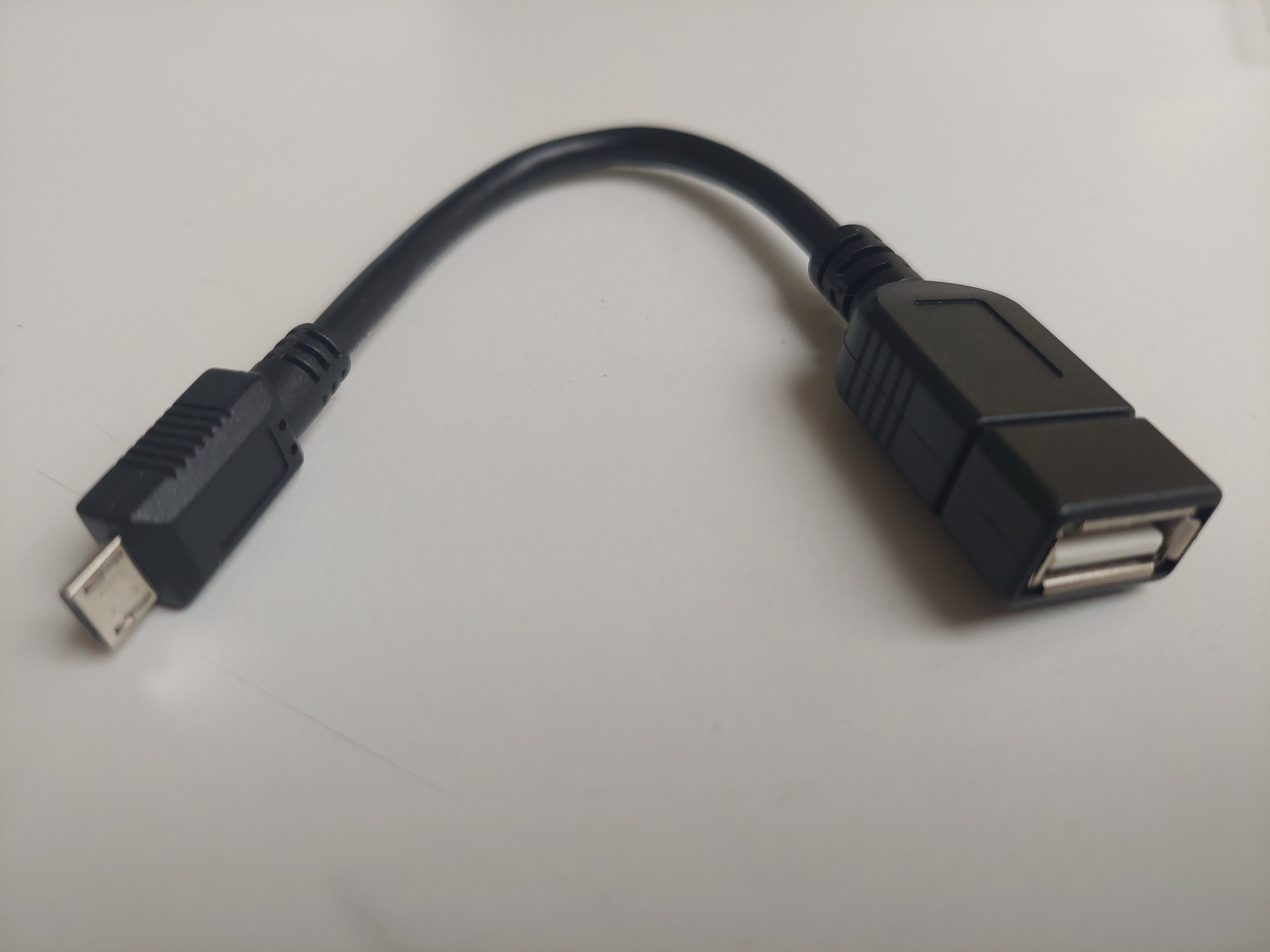
- micro USB male to USB female:
![]()
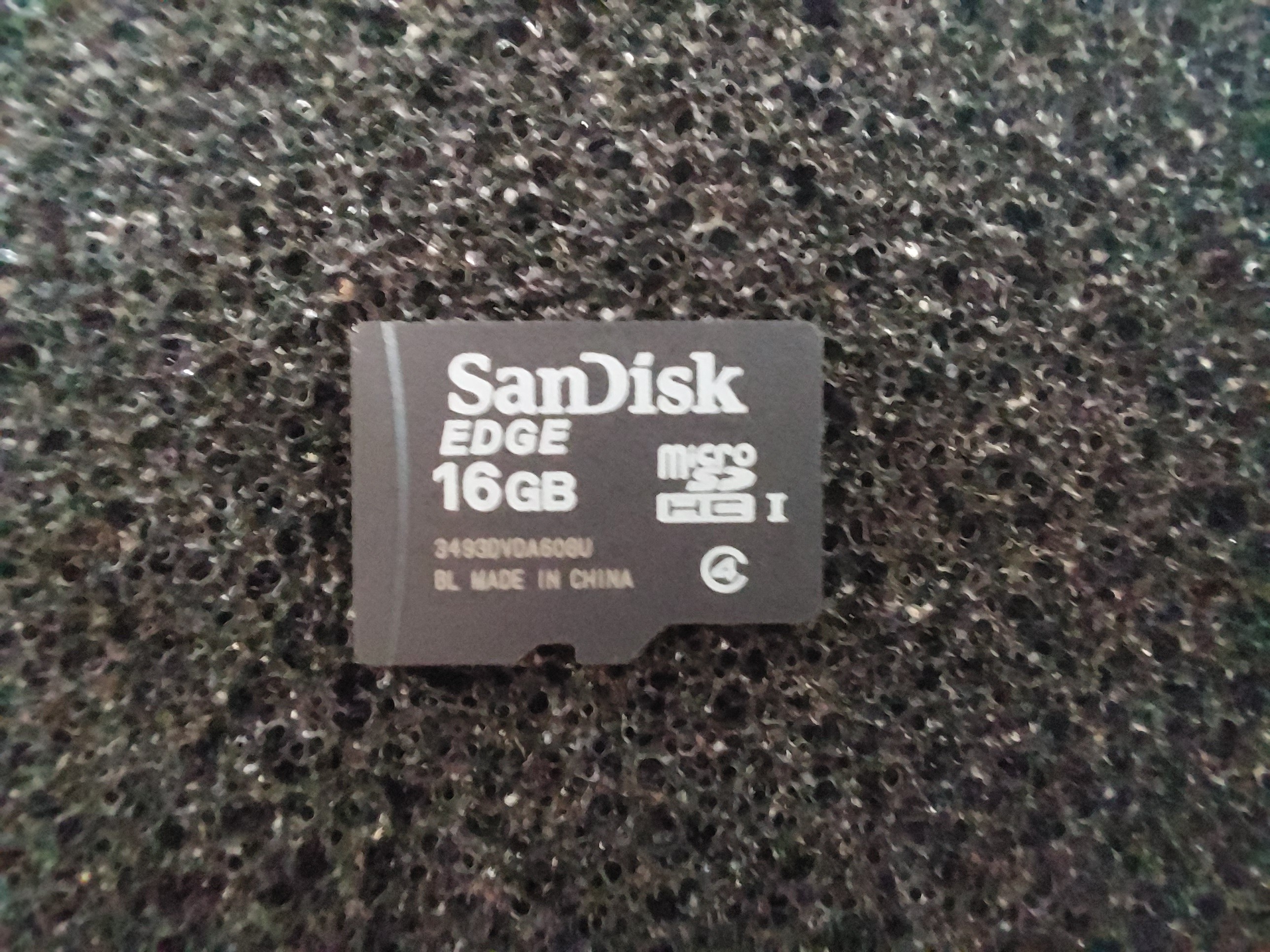
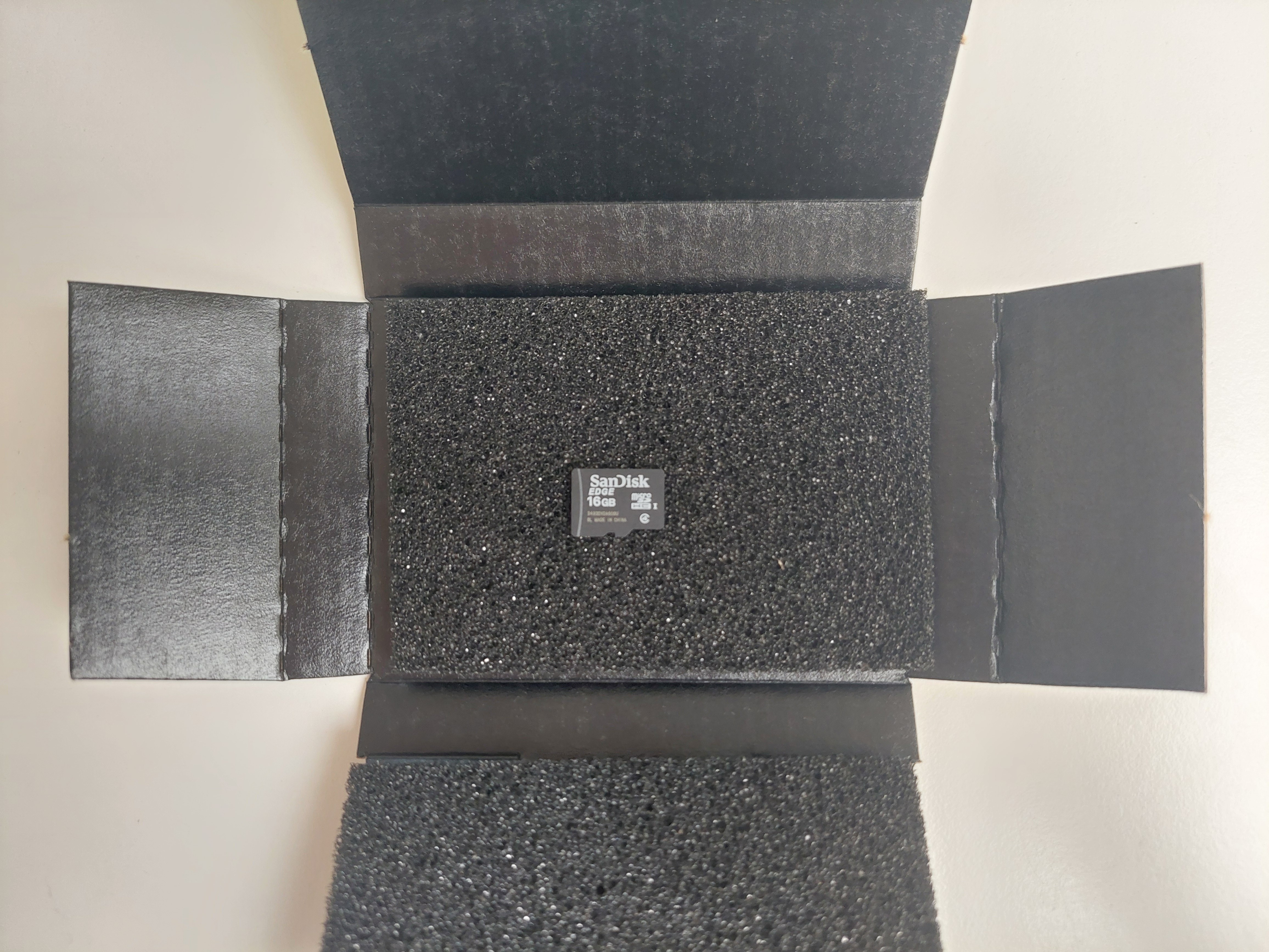
- micro SD card:
![]()
![]()
(the box was too fancy to not to show it, so enjoy!)
BallAudio - DF Player
We also tried to modelise the circuit of this video : https://www.youtube.com/watch?v=9w_AaIwlsE4 with this website https://wokwi.com/projects/new/esp32 .
However, it did not work as there is no MP3 dfplayer on the website, so we tried to cable physically the ESP32 we used in the first semester but they were all over heating, so we tried to de-soulder them. However they seem to have decide not to work anymore, the ESPs might be unusable ever again.
