Low cost stereo camera
Building a cheap stereo camera using COTS parts
Building a cheap stereo camera using COTS parts
To make the experience fit your profile, pick a username and tell us what interests you.
We found and based on your interests.
I got the second camera and two 170 degree wide angle lenses (1.8mm focal length). After calibration the disparity was terrible. I figured it was because I used the clips on the back of the cameras to hold them in place. Indeed a small movement of the lens is enough to render the calibration obsolete.
I printed a support that would hold them together at 100mm apart, the results were slightly better:

I think there is still room for improvements, but this proves the general feasibility of the idea.
Lessons learned:
I tried to find some information about the electronics on the board of the camera, but like a lot of cheap Chinese electronics it seems the used chip is not very documented, or at least not in English.
There seems to be only one chip doing all the work, there are traces going from the camera module to it, and the USB lines are also connected directly to the chip.
When calling lsusb in the command line it reports a 1e4e:0110 Cubeternet device for the camera. The manufacturer is listed as Etron Technology, Inc., but I was unable to find any datasheets on their website.
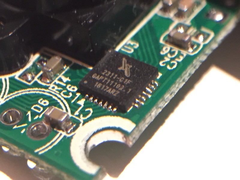
The code on the component itself didn't help much either:
If anybody has some more information about this particular device it would be welcome.
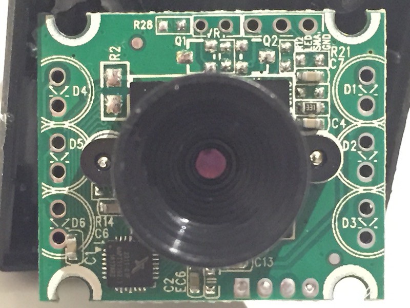
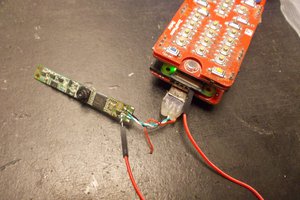
From the front the camera looks like it's missing a lot components. The diodes D1-6 are connected to Q2 which looks like a typical SMD transistor footprint, so technically it's possible to add some LEDs to the camera board, which is nice I guess...
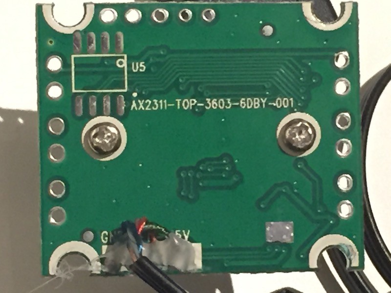
On the back there is some code, possibly some production code:
Also there is an 8-pin unpopulated footprint (U5), seemingly not a necessary part, omitted to lower production costs. The traces go to the main chip, perhaps some memory?
I don't want to spend too much time reverse engineering the hardware for now, as it seems to be working well enough to make a stereo camera with a pair of those.
The second camera arrived, but now how to distinguish between the two in Linux?
Consistently recognising connected physical hardware is important, in this case as left and right cameras.
When connecting two USB cameras in Linux they automatically appear as:
/dev/video0
/dev/video1
However there is no way to know if video0 is the left or the right camera, and this might even change after a reboot. To fix that Linux uses something called udev rules, there has even been a Hackaday article about how to set up a rule for a device. Basically based on the attributes reported by a device one can set a new name, such as:
/dev/stereo_camera/left
/dev/stereo_camera/right
First one needs to get the distinguishing information from the devices, for that there is a useful command:
udevadm info -a -p $(udevadm info -q path -n /dev/video0)
udevadm info -a -p $(udevadm info -q path -n /dev/video1)
This will print a lot of information about the devices. You should look at the block that starts with something similar to:
looking at parent device '/devices/platform/soc/3f980000.usb/usb1/1-1':
In there note down the idVendor and idProduct attributes for both cameras, these will distinguish the two devices.
To set up a new rule create a new rules file:nano /etc/udev/rules.d/81-stereo_camera.rules
Add the following lines, your attributes will differ obviously:
SUBSYSTEM=="usb", ATTRS{idVendor}=="0424", ATTRS{idProduct}=="9514", SYMLINK+="stereo_camera/left"
SUBSYSTEM=="usb", ATTRS{idVendor}=="1e4e", ATTRS{idProduct}=="0110", SYMLINK+="stereo_camera/right"
Finally reload the udev rules with the following commands:
udevadm control --reload-rules
udevadm trigger --attr-match=subsystem=usb
There should be some new devices under /dev/stereo_camera/*, execute the following command to check if the devices have been properly recognised:
ls -la /dev/stereo_camera/*
It will print the paths to the respective devices which will remain consistent over reboots:
/dev/stereo_camera/left -> ../bus/usb/001/006
/dev/stereo_camera/right -> ../bus/usb/001/005
The paths /dev/video0 and /dev/video1 still remain, but unlike /dev/stereo_camera/* it is not guaranteed that they will stay consistent over reboots (video0 for the left camera might become the right camera after reboot).
I ordered a $2 webcam from eBay to see if it actually works on a RPi, on which I intend to run the stereo camera in the end.
I received the camera and tested it. The image size is 640x480 pixels (0.3MP), which is just right for a stereo camera, a higher resolution would probably overwhelm the CPU. The image quality is not the best though and the lens absolutely not suited for the application.
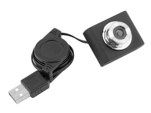
I opened the camera it to see if the lens was replaceable, the lens mount is a standard M12 screw-type, so I ordered a second camera and a pair of 170 degree, 1.8mm focal length lenses.
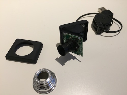
Notice how the lens depicted on the eBay image is not the same as the one it was shipped with...
Create an account to leave a comment. Already have an account? Log In.
@Solenoid I'm considering a pair of ELP cameras (https://amzn.to/2M4Drqr) with a 3D printed support, raspberry Pi 3B + and opencv. In your opinion, if correctly calibrated, this could work much better than yours? Is it possible to solve the shutters synchronization problem with an algorithm that gives me a 1-2 frame tolerance?
I'm not familiar any other packages than stereo_image_proc, the package allows to set the approximate_sync parameter to accept non-timestamp-synchronised frames.
You should get some disparity in any case, the cameras seem to have excellent specs, the limiting factor will probably be the RPi.
Nice work so far on this. What software are you using, opencv? Keep us updated on the progress, if you want to collaborate at all let me know, I'm working on the same problem in the context of autonomous drone. I'm using 2 Logitech 270 on raspberry pi (still cheap, but not as cheap as yours), got a basic pixel depth map going but got to work on the performance, and aligning camera's properly. here is my very in progress code: https://github.com/TaylorHawkes/guineapig/tree/master/3d2
The project is on halt for some time. The project on which I want to use this stereo camera isn't finished yet, so I just made a proof of concept. Now I'm dedicating my time to finishing other projects before I can continue this one.
To answer your question: I'm using OpenCV through ROS stereo node.
wanna work together at some point? Here's my project: https://hackaday.io/project/20731-cheapest-moble-robot-arm-platform
.Hi,
i'am sorry if this comment is not very positive, but i think you are wasting your time here ... There are may reason why stereo camera are expensive :
- sensors must be synchronized (exposed exactly at the same time)
- sensor data must be raw (no compression)
- sensor should be global shutter (or the sensors should only observe a static scene)
- mechanical assembly must be stable
Those cheap USB camera are rolling shutter, cannot be synchronized (or only with a hack) and data is compressed to be streamed over USB2.0. If you want to sense depth on a DIY cheap robot you are left with :
- using a kinect (probably the best option)
- using a cheap LIDAR (sill over 200$)
- design your own depth sensor (webcam + lasers)
- do SLAM with a single camera (but not with a cheap webcam)
Maybe an Intel D415 instead of a Kinect? ($150 https://click.intel.com/intelr-realsensetm-depth-camera-d415.html
Become a member to follow this project and never miss any updates
 medeiros1
 Rishi Bhatnagar
 Arya
Arya
Oh amazing to see this idea I am also working on the similar type of project its a camera lens project you can see here https://cameraslife.com/