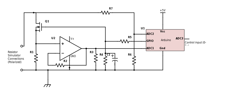
The first upgrade is to build a fuel level sender interface. The Locost has a fuel cell rather than a conventional fuel tank so there is no room for a conventional float arm based level sensor. Capacitive senders, though, just have a small tube that goes in the tank. The tube has a second concentric tube inside and the level is determined by measuring the capacitance between the inner and outer tube. Such senders are available through Ebay for around $30. The problem is that the sender outputs a voltage between 0.5v and 5v but the meter expects a resistance between 4 ohms and 110 ohms. The obvious way to interface is to use a voltage to resistance chip but they don't come with the right values and cannot take the 100ma that is necessary to drive the meter. So, I have decided to build a microcontroller based resistor simulator.
First a word about fuel level senders. Most of them have a variable resistor to ground. here are some typical resistance ranges (empty to full):
1. 240-33, standard aftermarket
2. 0-90, GM Type ’66 and later
3. 0-30, GM Type ’64 and earlier
4. 16-158, Ford Type ’87 and later
5. 75-10, Ford type ’86 and earlier
6. 90-0, Toyota and Nissan ’85 and later
7. 40-250, Late model GM
8. 10-180 VDO gauges
You can buy converters, but they are expensive and it is an interesting project to build one.
Older, non electronic, fuel gauges generally use "balanced coils" where there are two coils in the meter, one pulling the needle towards zero and one pulling the needle to full. The sender is essentially wired in parallel with one of the coils, thus changing the relative pull of the coils. If you simply provide a constant current or voltage based on the fuel level, the meter reading will vary with the battery voltage.
A simple solution should be to stabilize the voltage feed to the meter and then a constant voltage drive should provide a stable reading but I didn't want to modify the wiring of the instrument panel so I am working on a resistor simulator.
Another point worth noting is the harsh environment in automobiles. This requires special care in building electronics for them. I usually address the temperature range issue by installing the electronics away from heat sources, generally in the passenger compartment. Dealing with very low temperatures is not an issue for the Locost as I am not going to be using it when it is below freezing. Having said that, I usually try to use automobile grade components when I can get them. The second aspect of the harsh environment is electrical spikes and noise. The alternator often creates significant voltage spikes which I address by using Transient Voltage Supressors (TVS). Sensor inputs also need protecting to be safe. There is also a lot of high frequency noise which is best dealt with through a combination of shielding (metal enclosures) and a lot of capacitors and low pass filters in the circuits. Next, I will describe the circuit I plan to use for the converter.
 mircemk
 Tijl Schepens
 adria.junyent-ferre
 Yann Guidon / YGDES