-
Resistor Fuel Gauge Simulator: The final design
04/20/2017 at 22:24 • 0 commentsI have been away traveling for a while so am only just catching up. I decided to use a different circuit with a INA219 high side current and voltage sensor used to measure the current and voltage. As before, I used an AOI518 MOSFET as the "variable resistor". Power MOSFETs aren't perfect for this application as they are designed for strict on/off operation, but it worked. I started with an Arduino ProMini to provide the feedback control but it turned out to be too slow and its PWM capabilities were insufficient for fine control. I had a spare Teensy LC and this turned out perfect for the job. Enhancements to the circuit included a gate bias circuit that increased sensitivity by biasing the MOSFET half way between full on and full off. This requires calibration but that is easy to do.
I started by setting up the INA219 module using the available Arduino library. I set up a test program to calculate the effective resistance using Ohms law and the measured current and voltage. It worked well for fixed resistors. I was aiming for a resistance range of zero (approximately) to 110 ohms. They I added the mosfet with the control logic. Initially, I used "bang/bang" control driving the gate with a digital pin and with a 10 microfarad capacitor on the gate to dampen the voltage. This didn't provide fine enough control so I moved to PWM control on a Pro Mini but a 255 step PWM was still not fine enough control.
Next I added the bias circuit so that the whole PWM range was being used effectively. The gate was biased half way between pinch off and full on, similar to MOSFET audio amps. The PWM pin then drives the gate using a resistor chosen to just cut off the MOSFET with zero PWM count and just fully turn on the MOSFET with a full PWM count. I also changed to a Teensy LC (quite reasonably priced at around $12). This both gave faster response and provided a 12 bit PWM (4096 steps). This ended up as the final hardware design. I will add the schematic later as I have time. As I wanted the INA219 range to be 16 volts and 400ma, I had to modify the library as it didn't provide a call to set the full range values. You should be able to run with the existing settings and the library has the code to set the maximum voltage and current, but that capability doesn't seem to be callable from Arduino.
The bottom line is that the final system works well. I can provide a 0.5 volts to 5 volts input (as per my capacitive fuel level sensor) and get a simulated resistor output that varies between around 0.5 ohms and 110 ohms corresponding to what the fuel gauge expects. The software allows calibration of the range and correction of non-linearity. I will be publishing the Arduino code shortly.
The next project is a windscreen wiper synchronizer which I have just completed. The circuit should work well for other applications where you want to keep two motors synchronized in both position and speed but where you only have a single point in the cycle for synchronization (the home switch for windscreen wipers). More details to follow....
-
Low-Side current sensors
01/31/2017 at 18:12 • 0 commentsAfter experimenting a while with the above circuit, I found that low side current sensing with only about 20mV signal required a lot of care in circuit design to minimize drift and offset. The TCA271 was OK as you can add an offset nulling circuit but I didn't want to have to trim the circuit so I started to look for a suitable alternative opamp. In searching I discovered the Texas INA219 high side sensor. This is available as a module from around $2 from China up to around $10 from Adafruit. The INA219 not only includes a suitable high side current sensor but also includes a bus voltage sensor, which I need for this circuit, and a 12 bit ADC. It connects to a microprocessor using the I2C bus. I have now changed the circuit to put the MOSFET on the low side of the sensor input. I am waiting for delivery of the INA219 modules that I have ordered and will report on the results when I have them. The microcontroller will remain an Arduino mini pro but the code will now read the input over I2C from the INA219, driving the MOSFET as per the current design. More to follow....
-
Mosfets in Saturation
01/25/2017 at 22:50 • 0 commentsIn trying to choose a MOSFET for the project, I researched how to use MOSFETs in their non-saturated region. Modern MOSFETs are optimized for switching so their saturation regions are small and their headroom when non saturated is limited so I decided to use an old MOSFET. I chose an IRF640 as I happen to have a bunch of them. Next I plan to test out how they behave in their saturation region which is how MOSFETs are used in audio amplifiers. I will also be using a separate opamp for the current sensing resistor. I have a spare TLC271 which is optimized for single power rail usage so that is what I will use. More when I have built the test circuit.
-
Fuel Sender Adaptor Circuit
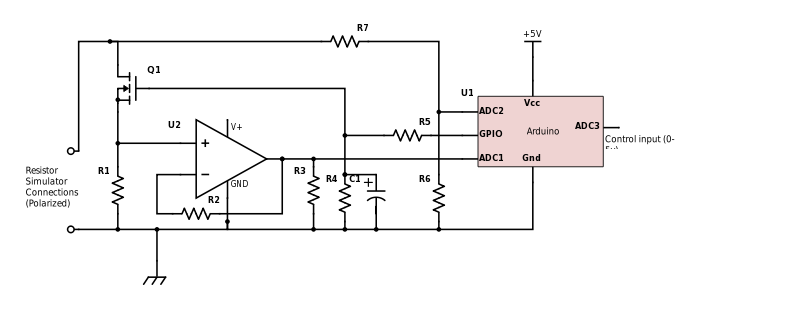
01/25/2017 at 00:45 • 0 commentsHere is a schematic of the circuit I plan to use:
![]()
R1 is the current sense resistor. It will probably be around 0.1 ohms, giving 10mV at 100ma. U2 is a opamp with the gain set by R2 and R3 to bring that voltage up to the range for the ADC. The voltage across the simulated resistor goes into ADC2 through a voltage divider designed to support up to 15 volts across the "resistor". The current through the "resistor" is controlled by a GPIO pin with simple "bang bang" control. It drives the gate of a MOSFET via a current limiting resistor/ low pass filter comprising R5 and C1. R4 is for gate protection, say 1 megohm. The time constant for C1 R5 is set to about 1 second as fast response is not required. This also biases the MOSFET into its linear region where it will act like a somewhat non-linear voltage controlled resistor on its own. Operating the MOSFET in its linear region increases its dissipation but at less that 100ma at less than 12 volts, this should be less than 1.5 watts which is easily handled by any decent power MOSFET without a heatsink.
Right now, I am deciding on what MOSFET to use. It must fully turn on at less than 5 volts, have the lowest possible gate threshold voltage and an on resistance of no more than a couple of hundred milliohms. I will probably use a AO518 as I have a lot of them.
The code is in two parts. One takes the control input from ADC3 to set the "resistor" value. This will use a small lookup table with interpolation to provide first order correction for non-linearity. The second part maintains the effective resistance by providing closed loop control of the ratio between the current sense voltage and the overall "resistor" voltage. I was thinking of using a PWM output with PID control but as it is OK for the response time to be slow in this application, simple on/off control with the low pass filter should work well.
Although the circuit as specified uses an Arduino mini-pro with a separate opamp, I am tempted to use a Cypress 4200 PSOC chip as they can be set up to handle both the analog part and the digital part on the one chip. It is somewhat overkill, but simple dev boards are available for $4 so it is certainly cheap enough.
Locost Electrics
Car electronics projects for home built cars and hot rods. It includes a capacitive fuel sender interface and a wiper synchronizer.