 Aneesh1111
-
1Get to the electronics
You only need to unscrew (at most) 8 screws on the top of the robot. The ones connecting the top platform to the metal rods at the corners of the robot. (I also unscrewed the raspberryPi camera mount so I could fully detach the top plate).
-
2Locate the power cables
There are many power/data cables you could measure.
- Battery --> Motor controller board (MCB)
- MCB --> Motor 1
- MCB --> Motor 2
- MCB --> Bluetooth
- MCB --> RaspberryPi
- RaspberryPi --> Lidar (power)
- RaspberryPi --> Lidar (data)
- MCB --> Motor (data - this does not work with these current sensors as it distorts the data signal causing the motors to not send/recieve data)
-
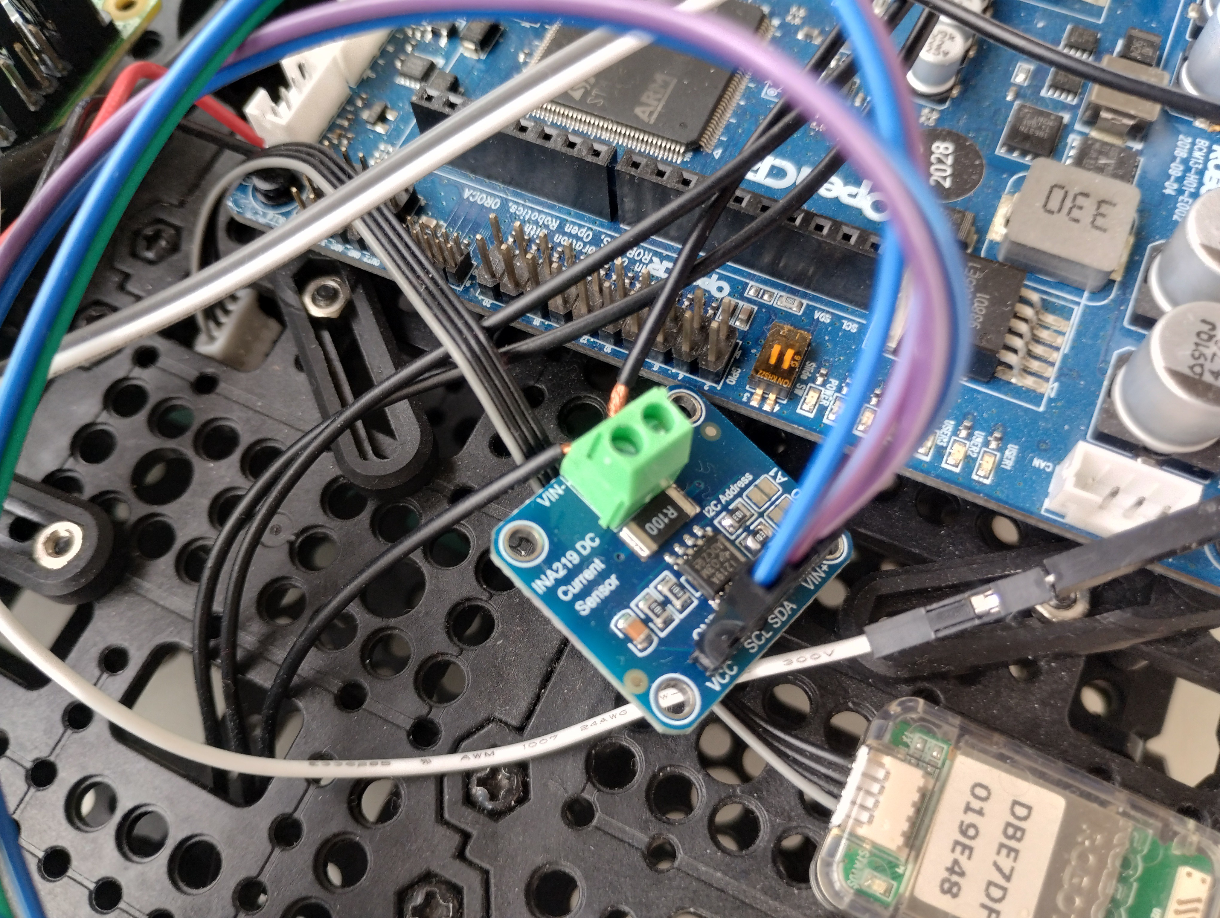
3Insert the current sensors
![]()
Once you've located which cables you want to log the energy from - cut & strip the wire and insert your INA219 current sensor inbetween - paying close attention to connecting the supply side to VIN+ and the load side to VIN- (otherwise you get a negative current).
Then, you can connect VCC, GND, SCL, and SDA to the relevant ports (to the TCA9548A).
-
4Optional
Connect an external battery supply to power the INA219 boards and the TCA9548A - such that the battery on the robot is not getting used up by them (if you want to log where the power is being distributed throughout the robot - this step is important).
TurtleBot3 WafflePi Energy Logging
Logging the energy usage of all components on the turtlebot3 wafflePi (motors, motor controller, lidar, raspberryPi, etc.)
Discussions
Become a Hackaday.io Member
Create an account to leave a comment. Already have an account? Log In.