Sebastian
-
Topology (2)
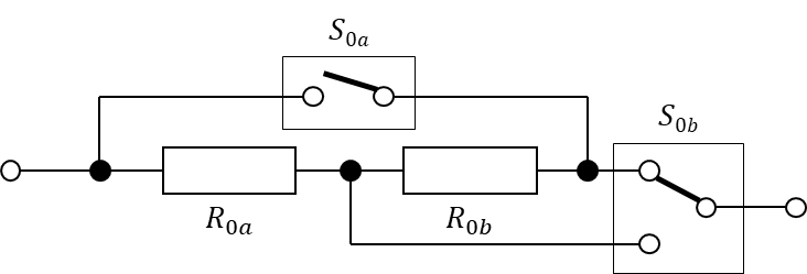
05/09/2024 at 22:18 • 0 commentsIn the last post we had a look at a simple topology that allows us to switch between a series and a parallel connection of two resistors:
![]()
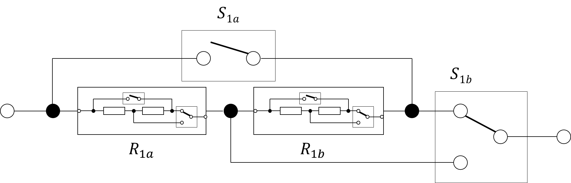
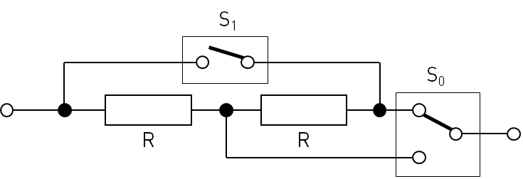
Now we nest these structures so that we have four resistors:
![]()
The interesting part here is that two of the four switch states of the outer structure don’t provide any new resistance values: With S1a open and S1b bypassing R1b we’re left with R1a. (Again, this assumes the R1a = R1b.) If S1a is closed and S1b in the upper position, then the total resistance will be 0, exactly like with only R1a. Here I assume ideal switches. The series and parallel connection of both R1a and R1b alone is worth it though.
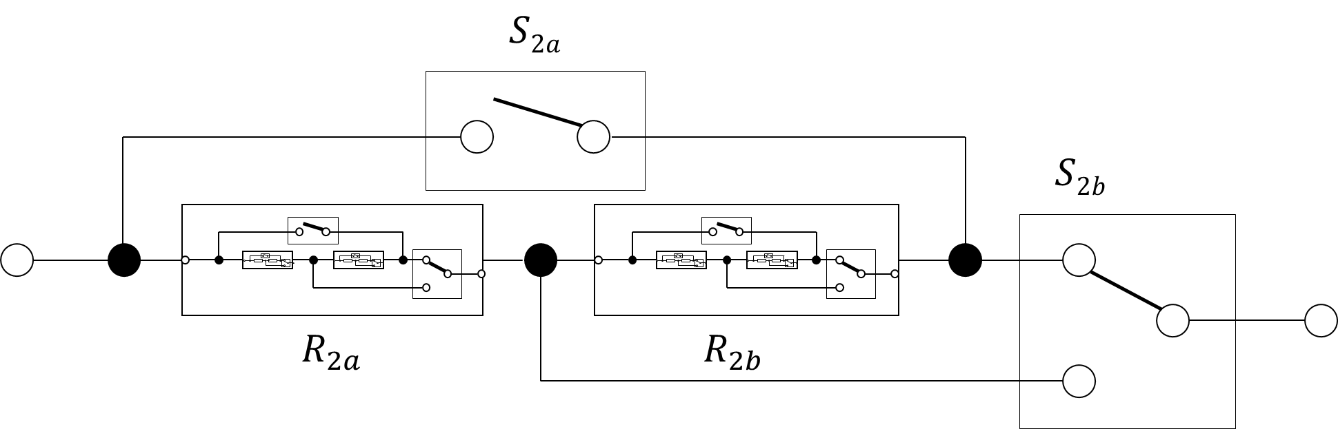
Doing that once more and we get eight resistors, barely visible in this picture, but with a similar effect like with the previous nesting.
![]()
With a total of 14 switches there are 2^14 = 16384 switch states. As briefly discussed, many switch states might lead to the same resistance values (actually, by far not only the two examples described above). In fact, as we will see later, much more than half of the switch states result in a short circuit.
However, states with equal resistances might not be equally suited for the intended application, because in some cases they differ in the power rating we can achieve. But even then, for certain resistance values there might be multiple states with the same resistance and power rating, but with a different number of active switches. This could minimize the contact resistance (but this is not necessarily the case with the dual throw switch) and it might be a good idea to energize as few relays as possible.
This begs the following three questions:
- How many and which distinct resistance values can be selected?
- What power rating can we achieve per resistance value?
- What is the best switch combination (here: least number of relays energized for the highest power rating) to realize each of the selectable resistance values?
To answer this I wrote a small python script that calculates these things for us. I’ll assume all resistors are 10 Ω with a 50W power rating. The results are presented in the following table.
# Resistance Number of Valid
Switch CombinationsMaximum Power Energized Switches (Ω) (W) 1 0 9472 nan 4 2 1.25 1 400 14 3 1.428571 4 350 13 4 1.538462 4 325 12 5 1.666667 18 300 11 6 1.818182 12 275 11 7 2 48 250 10 8 2.142857 4 233.333333 11 9 2.222222 50 225 9 10 2.272727 4 220 10 11 2.307692 4 216.666667 9 12 2.352941 2 212.5 8 13 2.5 209 200 7 14 2.727273 8 183.333333 10 15 2.857143 60 175 8 16 2.941176 8 170 9 17 3 8 166.666667 8 18 3.076923 4 162.5 7 19 3.157895 8 158.333333 9 20 3.333333 384 150 6 21 3.448276 8 145 8 22 3.529412 8 141.666667 7 23 3.636364 4 137.5 6 24 3.75 28 133.333333 8 25 4 370 125 5 26 4.166667 28 120 7 27 4.285714 28 116.666667 6 28 4.444444 14 112.5 5 29 4.615385 8 108.333333 8 30 5 933 400 6 31 5.263158 8 95 7 32 5.454545 8 91.6666667 6 33 5.714286 4 87.5 5 34 5.833333 4 262.5 11 35 6 32 187.5 7 36 6.5 4 203.125 10 37 6.666667 356 300 5 38 7.142857 32 280 6 39 7.333333 8 229.166667 9 40 7.5 50 266.666667 5 41 8 20 250 4 42 8.333333 28 166.666667 8 43 8.571429 28 131.25 6 44 9 28 180 7 45 9.166667 4 103.125 9 46 9.375 8 120 7 47 10 1074 200 3 48 10.666667 8 120 7 49 10.909091 4 103.125 5 50 11.111111 28 180 5 51 11.666667 28 131.25 6 52 12 28 166.666667 4 53 12.5 20 250 6 54 13.333333 50 266.666667 7 55 13.636364 8 229.166667 5 56 14 32 280 6 57 15 356 300 4 58 15.384615 4 203.125 4 59 16.666667 32 187.5 5 60 17.142857 4 262.5 3 61 17.5 4 87.5 9 62 18.333333 8 91.6666667 8 63 19 8 95 7 64 20 933 400 2 65 21.666667 8 108.333333 6 66 22.5 14 112.5 7 67 23.333333 28 116.666667 6 68 24 28 120 5 69 25 370 125 3 70 26.666667 28 133.333333 4 71 27.5 4 137.5 8 72 28.333333 8 141.666667 7 73 29 8 145 6 74 30 384 150 2 75 31.666667 8 158.333333 5 76 32.5 4 162.5 7 77 33.333333 8 166.666667 6 78 34 8 170 5 79 35 88 175 4 80 36.666667 8 183.333333 4 81 40 209 200 1 82 42.5 2 212.5 6 83 43.333333 4 216.666667 5 84 44 4 220 4 85 45 50 225 3 86 46.666667 4 233.333333 3 87 50 48 250 2 88 55 12 275 3 89 60 18 300 1 90 65 4 325 2 91 70 4 350 1 92 80 1 400 0 Since the selected topology does not inherently allow to open the circuit, an additional series-connected relay is required. This relay is not included in the total number of energized relays.
-
Topology (1)
04/18/2024 at 20:15 • 0 commentsIn this application the focus is on power handling capability, not so much a high resolution (high number of resistance values) or precision. This is why the topology used in the Programmable Precision Resistor is not as suitable for this application as it has been before. Also my ELMA cases are really small (and I mean really small, so thermal considerations will be challenging), so I can’t simply increase the number of power resistors and relays in the process. That’s why I’ll stick to the original plan of using 8 power resistors.
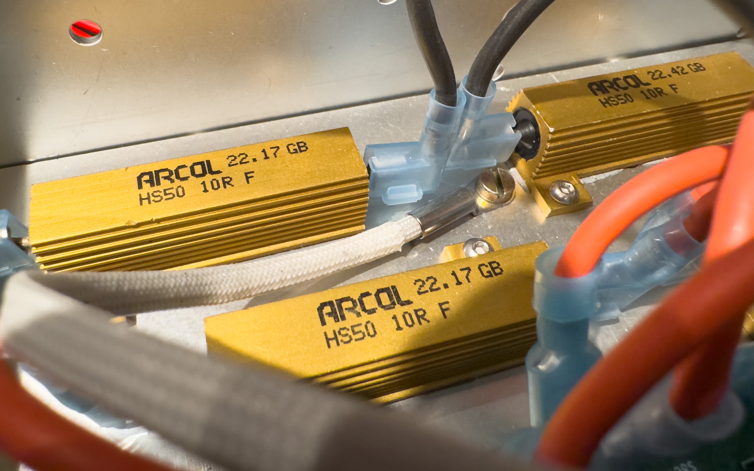
![]()
Three of a total of eight power resistors used in this project Instead the idea is to find a topology where I can select different resistance values by either connecting the resistors in series or in parallel. Let’s first have a look at a circuit for only two resistors.
![]()
A simple circuit allowing to switch between a series and parallel connection of two resistors. It requires one single throw and one dual throw switch. For this design I assume that both resistors are identical, both in their resistance value R as well as their power rating P. It’s very obvious how this circuit works, but here are the current paths for the different switch states anyway:
![]()
Switch states of the presented topology Since the math behind this is really simple, here are the results without any further explanation.
S0a S0b R0 P0 I0 U0 0 0 2R 2P √(P/R) 2R√(P/R) 0 1 R P √(P/R) R√(P/R) 1 0 0 unlim. unlim. 0 1 1 R/2 2P 2√(P/R) R√(P/R) Switch states and the associated electrical parameters And now we have our basic building block that we’ll use in the next post of this series.