There are two (possibly more) good reasons for using a separate power supply for the TEC cooled linear CCD.
The computer's USB will be unhappy to power the peltier-element.
The opamp requires ±5V to operate
The PSU consists of a small ±6V 10VA transformer for the CCD-circuitry, and a slightly bigger ±6V 24VA for the TEC alone. I've chosen to use two separate transformers to avoid an (inevitable?) asymmetric load if the TEC was to be powered by one of two outputs of a single larger transformer. (If this reason is invalid it's because I'm a whale biologist chemist and not an electrical engineer).
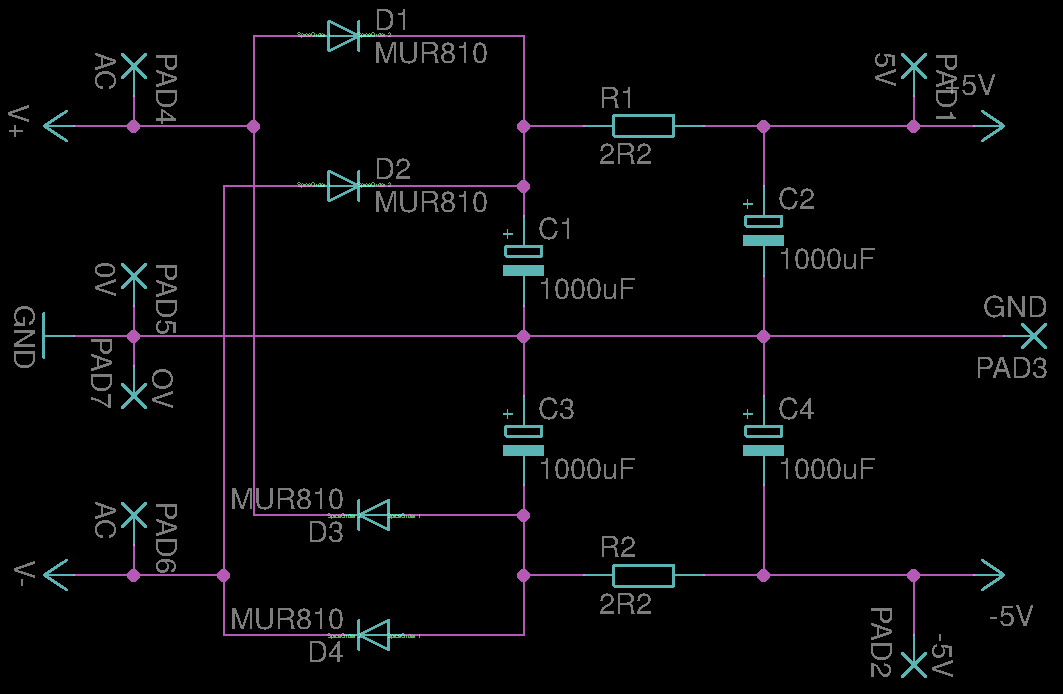
The CCD PSU
The CCD PCB has separate linear regulators (79L05 and 78L05)¹ for the analog and digital parts of the circuit that are all fed the same unregulated ±6V from the RC-filtered output from the small 10W transformer.
The current draw is < 30 mA, so the voltage from the PSU will hopefully stay above 7V, or the regulators will drop out.
The schematic is here:
There's no other reason for the choice of components, than; it was on my shelf.
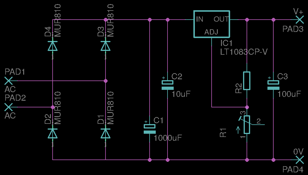
The TEC PSU
Is regulated with an LT1083 to make sure it the TEC's max-voltage (4.2V) is not exceeded. The schematic is:
And here they are, all boxed up:
[insert pretty pic of the psu]
[1] It's a bad choice for more than one reason, I know. Expect to see a LT1964/LT1761 or similar if I ever decide to improve upon it.
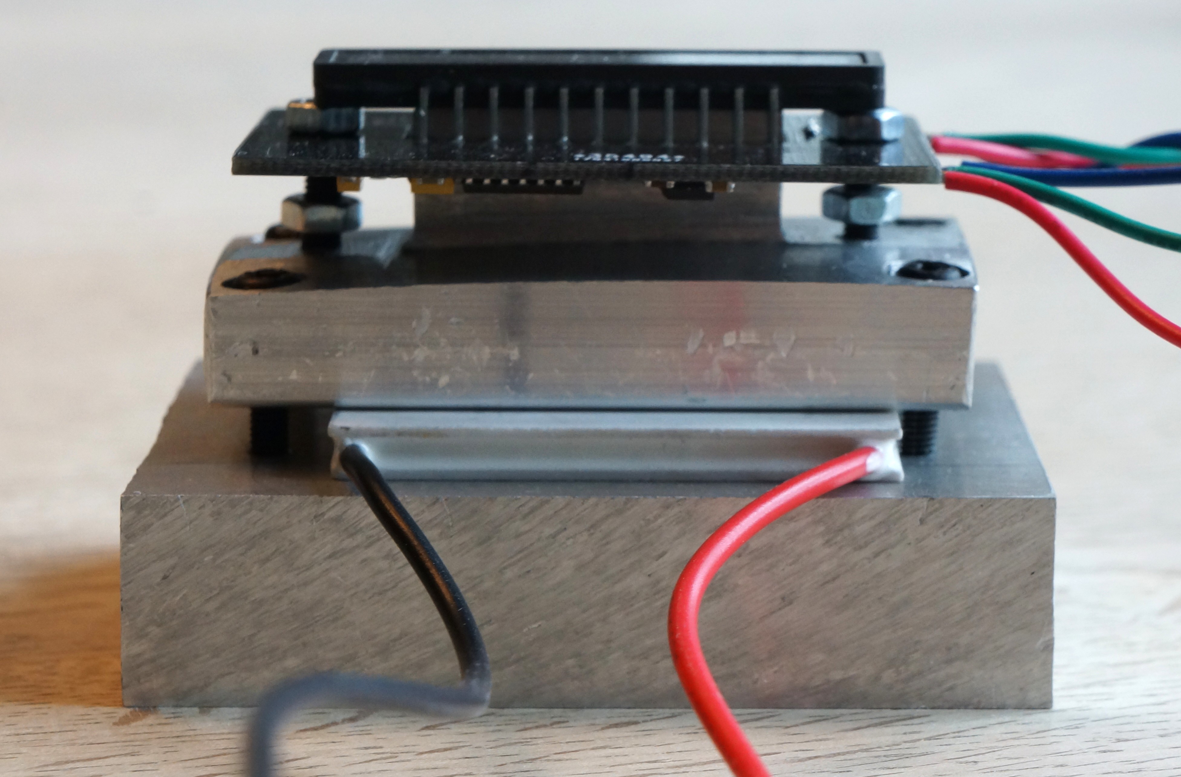
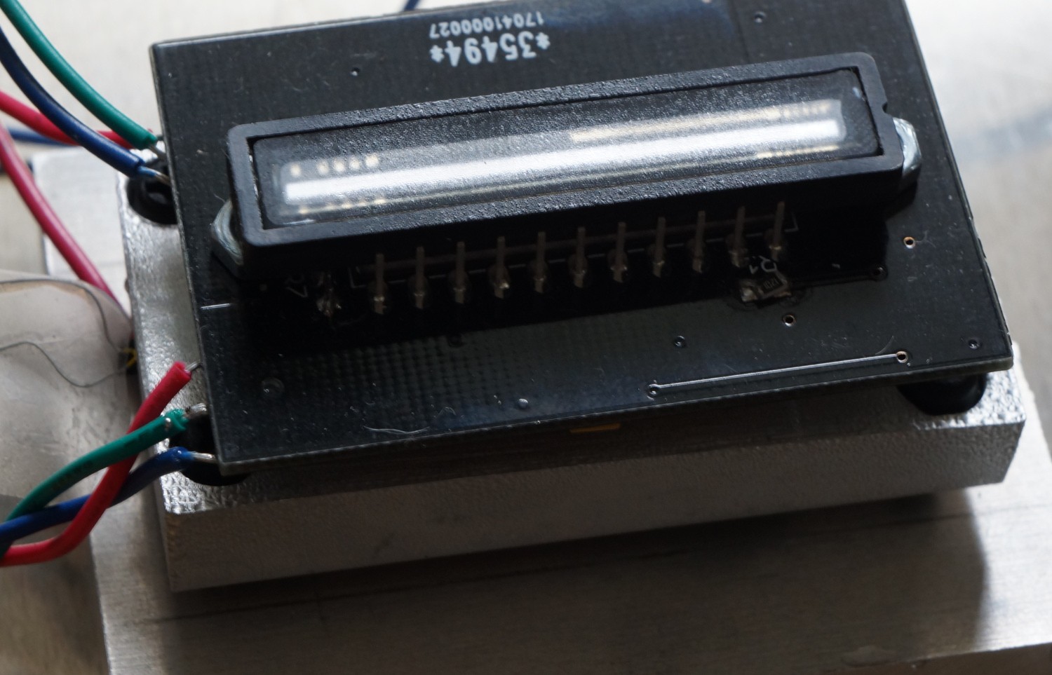
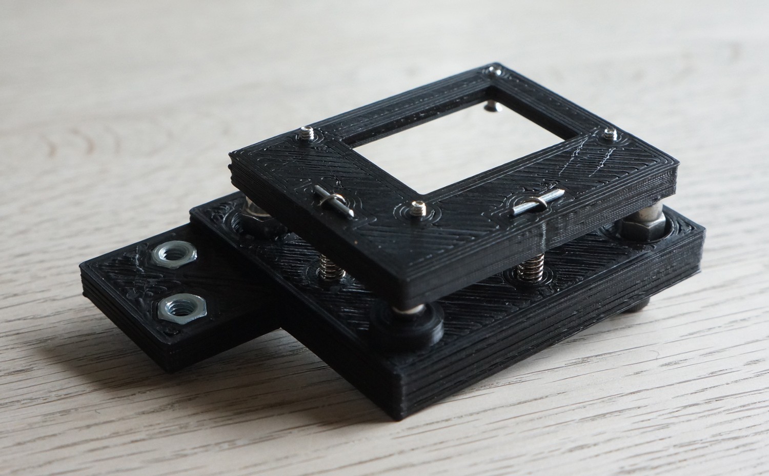
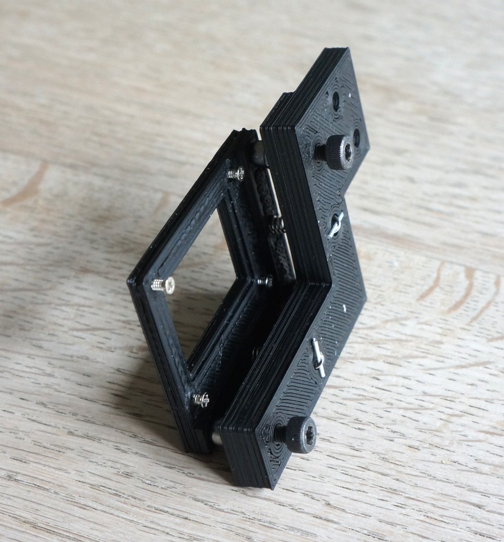
The sensor in the Raman spectrometer is the linear CCD module.
However, because the CCD drowns in dark current when the integration
time is longer than 1s, the TCD1304DG is mounted on a cold tip that's
thermo-electrically cooled using a standard TEC1-03506 running at 4.2V (but the photograph shows the CCD with a TEC1-12706).
Here it is with the right peltier element. The temperature drop was ~25°C, which gives a reduction in dark current of almost an order of a magnitude. Of course it caused a lot of condensation on the CCD, but when complete, the spectrograph will be sealed up together with bags of dessicant.
An STM32F103 "blue pill" connected to a 10kΩ thermistor mounted on the cold tip displays the temperature on an ILI9341 display.¹ The voltage drop across the TEC is also measured, just not at the time the photograph was taken. The firmware may be found in the files section of the project.
Furthermore, the CCD is placed in a more elaborate circuit than the datasheet's typical drive circuit.
The most notable new features are:
ADC input signal conditioning
Separate power supplies for the digital and analog sections
The
output from the CCD is upside-down and doesn't quite match the ADC of
the STM32F401RE's input range of 0-3.3V. To fix these issues the output
is fed to an AD8021 opamp² working as a differential amplifier:
The gain is:
G = - R₂ / R₁
we
have an input range of 1.9V (2.5-0.6V), but want 3.2V (actually 3.3V
but I don't want to risk clipping the signal), so G should be -1.68.
There’s probably a point to the resistor values in the typical drive
circuit (noise?), so R₁ is chosen to be 150Ω. The gain then dictates
that R₂ should be 252Ω. Setting Vref to 5V (it is in the complete
circuit) R₃ and R₄ can be found by solving:
Vout = 3.2V    when Vin = 0.6V        and
Vout = 0V      when Vin = 2.5V
One solution is (almost) R₄ = 150Ω and R₃ = 330Ω
The CCD-circuit in its entirety is shown here:
If I were to redo it, I would substitute the 78L05 and 79L05 voltage regulators (U3-4 and U2) with LDOs LT1761 and with LT1964.
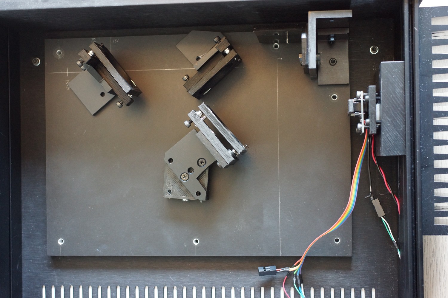
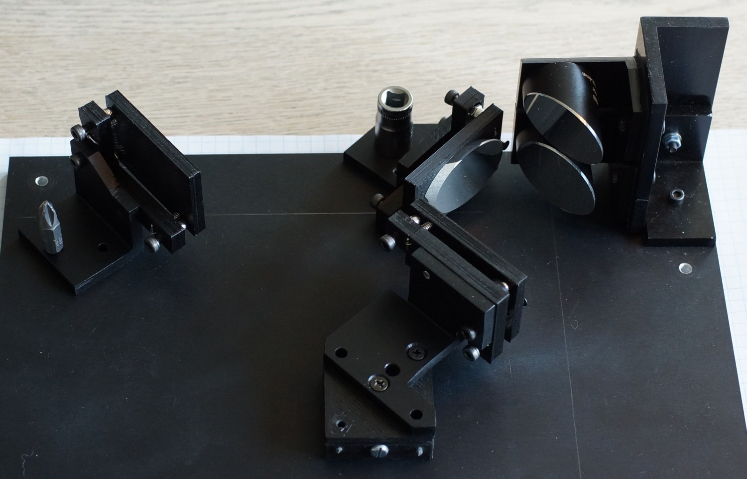
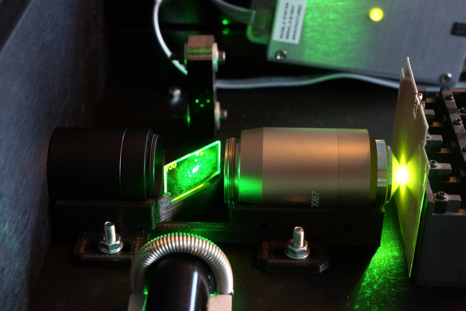
An overview of the spectrograph's geometry. On the left are the mirrormounts for the folding mirrors. In the top right corner is the mount for the off-axis parabolic mirrors. Center right is the thermoelectrically cooled CCD.
A: A quick back-of-the-envelope estimate would be:
laser: 250€
microscope objective: 150€
diffraction grating: 125€
filter+DIC-mirror: 75€
OAP-mirrors: 350€
elliptical mirrors: 150€
lens tubes, fiber adapters etc: 100€
fiber optic: 100€
cases: 100€
linear CCD module: 25€
connectors: 25€
misc electronics: 100€
So all in all around 1500€. It can certainly be made cheaper, but now you have an idea.
Q: What's with the expensive laser?
A: If you want an instrument capable of making reproducible measurements, you need a stable monochromatic light source. Cheap lasers are neither. However, with patience you can find used JDSU and Coherent lasers for somewhat cheap (100-300$). https://erossel.wordpress.com/2015/07/26/clear-as-the-mississippi/
Q: What's with the not so cheap microscope objective?
A: The intensity of the Raman signal is roughly proportional to the numerical aperture squared, so you want as high NA as possible. You can get cheap microscope objectives with NA > 1, but they are oil immersion with a working distance not much longer than standard cover glass thickness (0.17mm). The OEM version of the Nikon CFI VC 20x NA 0.75 was the cheapest high NA objective I could find with a long working distance (if you consider 1mm to be long) - and it's made for fluorescence applications so there won't be any autofluorescence.
Q: What's with the expensive edge filter and dichroic mirror?
A: You need efficient blocking of the Raleigh-scattered light, so you need proper filters. And they weren't that expensive - I bought production overruns from Omega.
Q: Why don't you have a slit in your spectrograph?
A: A slit is a waste of light if you cannot focus the entire length of the slit onto the linear CCD, and for that you need a cylindrical lens. Both the slit and the lens are expensive, so I chose to simply use the optic fiber aperture as the point source.
Q: What's with the custom fiber optic patch cable?
A: The raman signal is weak. I wanted a fiber optic that wouldn't pick up light pollution. It was 30€ extra - but of course around 80€ more than a lucky *bay find.
Q: Why the super expensive mirrors?
A: The off-axis parabolic are just not cheap, and once you get into a serious collection of mirrors, the tendency is to push it as far as possible.
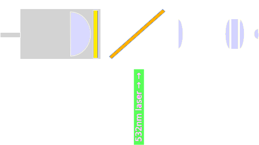
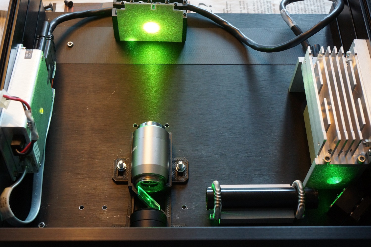
The laser is a 10 mW JDSU µgreen 532 nm laser. It operates in single longitudinal mode (SLM). The laser has no beam shaping optics, and the beam is somewhat divergent. This is "fixed" with a beam-expander (the long black tube). I'm not sure this is essential. Everything was carefully aligned one component at a time.
I would recommend a kinematic mount for the dichroic mirror - I didn't have that at the time of writing, I had a hair-drier (to heat, soften and adjust the 3D-printed holder). It could look something like this:
The "target" is an electroluminescent backlight that I use because it fluoresces in the 532nm laser light.
Here the EL-backlight is placed in the focal point of the microscope objective. In the background you see a razor blade beam dump.
Everything, literally, needs to be carefully aligned. Below you see the difference in light output before and after the last alignment of the dichroic mirror (oh and this time it's not the EL-backlight fluorescence we're looking at, but the fluorescence of a solution of tetraphenylporphyrin):
 esben rossel