Roger
Roger-
Luggable PC at Hackaday LA February Meetup
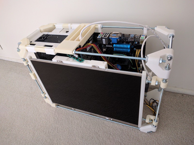
02/25/2017 at 02:28 • 0 commentsThere's nothing like a deadline to drive progress! I wanted to show the latest progress at this month's meet, but I had dismantled threaded rod box V1 and V2 was far from completion. A few frantic nights of work resulted in something I could bring to the meet. It was missing several pieces I didn't have time to print, but good enough for a show-and-tell.
There will be a more detailed write-up after I catch up on sleep, but the most significant new feature was the screen mount. I had been focused more on the other parts of the project, and had been recycling the same screen frame used in Easel Frame v1. It was sorely needing an update to match the latest evolution in the design.
Behold, the folding, rotating, transforming screen of the latest luggable PC! (Thanks to Shulie for the animated GIF.)
![]()
-
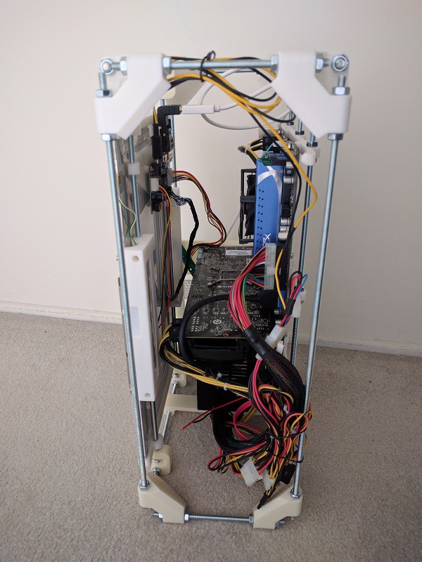
Threaded Rod Box V1
02/07/2017 at 23:59 • 0 comments![]()
Here's exploration of a more traditional layout, putting everything in at right angles in a box. The hope was that the lack of odd angles means an easier time fitting things together. In CAD, it looked like it could be a win.
Putting things together in the real world showed otherwise. Yes, we gained some volume with some components fitting nice and snug, specifically the PSU hovering over the unused expansion slots of the motherboard. But putting the motherboard and the screen parallel to each other opened up a huge wasted volume in between them. Volume that wasn't wasted with the earlier triangular layout, which had them leaning towards each other.
![]()
The culprit is, unsurprisingly, the GPU sticking up inconveniently in the middle of everything. This is why several people suggested that I look into PCIe brackets/extension cables. I agree things would be much easier if the GPU can be relocated!
I looked into the boxy layout because I had been evaluating a move to Misumi custom configurable aluminum extrusions and connectors. From what I can see, it would be trivial to bolt together a box with dimensions of my choosing, and stuff it with my parts. Such a switch would be easiest if I can make a simple box work for me, sadly this particular box is not a net win. But hey, it's only the first draft.
I'll do a few more variants of the box idea to see how far I can take it. But if I can't manage to think inside the box, it's not a total loss. Misumi does offer free-angle brackets allowing arbitrary angle on a single axis, which is well worth exploring.
-
Got on Hackaday.com!
01/28/2017 at 20:03 • 0 commentsWow, I did not expect to get a write up by a member of hackaday.com talking about this project. Pretty cool!
I appreciate the attention and the thoughts about building a PC in this style, and I just want to raise a gentle reminder that this is a work in progress and still in the very early stages. Stay tuned...
-
Luggable PC at Hackaday LA January Meetup
01/26/2017 at 00:05 • 0 commentsThe Luggable PC project had its first public outing yesterday: I brought Easel Frame V3 to Hackaday LA January Meetup. It was pretty much as documented earlier except it had the Mini-ITX board installed instead of the full ATX motherboard. (Their GPU slot were at different locations and I wanted to test both would work in the V3 design.)
I was pleasantly surprised by the level of interest the project attracted. I had anticipated that "just a PC" wouldn't be interesting to the crowd in comparison to the more typical maker projects present but I was wrong. I had a lot of fun explaining the motivation of the project and seeing quite a few faces light up in "hey that's a good idea" kind of interest. I got some good questions about the design trade-offs I'm prepared to make, and some suggestions.
One suggestion was from a local 3D printing pioneer (whose name I'm drawing a blank on right now) who recognized the threaded-rods-and-nuts building technique I copied from the old RepRap 3D printers. He suggested that I look into the aluminum extrusion building blocks popular with current innovators in the 3D printing space, which I will definitely do.
I was also encouraged to document the project here on Hackaday.io, which resulted in the page you are reading now. I hope it will find a more like-minded audience here than the random babbles on my personal blog where I had been documenting my projects.
Sadly, I had so much fun talking to people I forgot to take some pictures of it sitting in the Supplyframe DesignLab. Maybe some other photos from the event will surface.
The parking availability at the meetup location is not great, so I took public transit in the form of LA Metro Gold Line. This turned out to be a great test run of the design's portability. The trip taught me three major items:
- It is far too conspicuous: I wanted attention at the meetup but didn't need any attention on the train. Last night I solved this problem with a big black trash bag but a more elegant solution will be needed.
- Restore the handle: The screen sub-assembly had been adjusted as high as it will go, which partially blocked the top threaded rod and I could no longer use that rod as a convenient handle. If the screen will stay at that location, I need to devise a separate handle.
- Add physical isolation: I had to set the frame down on the ground at various points (dig up my TAP card for the turnstile, etc.) and no matter how gentle I try to be, every time I set it down I could hear and feel many pieces rattle against each other. At the very minimum I need to install rubber feet on the bottom, and start thinking about other mitigation against physical shock.
-
Easel Frame 3.0
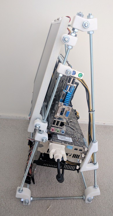
01/25/2017 at 23:09 • 0 commentsThe size of the V2 frame were conservative, mostly dictated by the ATX PSU sitting in the base. Seeing V2 in reality made me realize I'm going to need more room, I just wasn't sure how much more. To explore the upper bound of what I can build with materials already on hand (the 18-inch long threaded rods) I pushed the corners out to the maximum for Easel Frame V3.
The screen support assembly was recycled from V2, which meant it was not optimal but serviceable for the purpose of iterating on this idea. The ATX PSU is still sitting in the base, but no longer the focus of the base as it once were. Now it's just sitting on a little tray across the bottom of the frame.
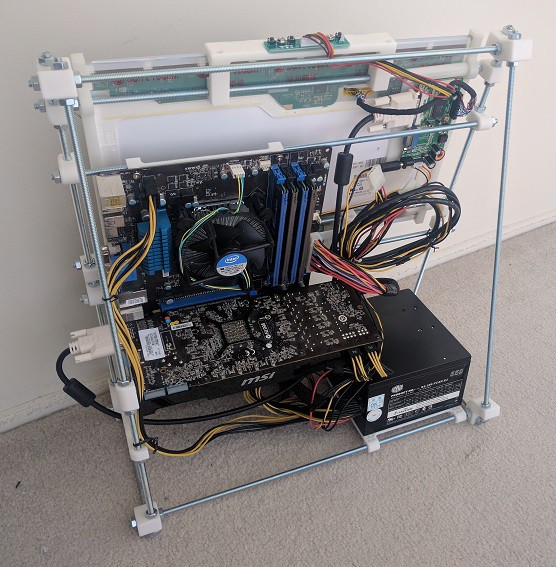
The focus for V3 is the full-ATX motherboard and the GPU sitting in it, which are the final major components to be integrated into the design. Frame V3 placed each of them on an independent sub-assembly that I could move around and adjust to explore the positioning and layout of the major components.
Happily there is more than enough room this time around, which means we've bracketed the range of solutions. V2 proved "too small", V3 proved "too big", so following iterations will narrow down the range until we find "just right".
(Also: I'm getting better at managing the wires.)
![]()
![]()
-
Easel Frame 2.0
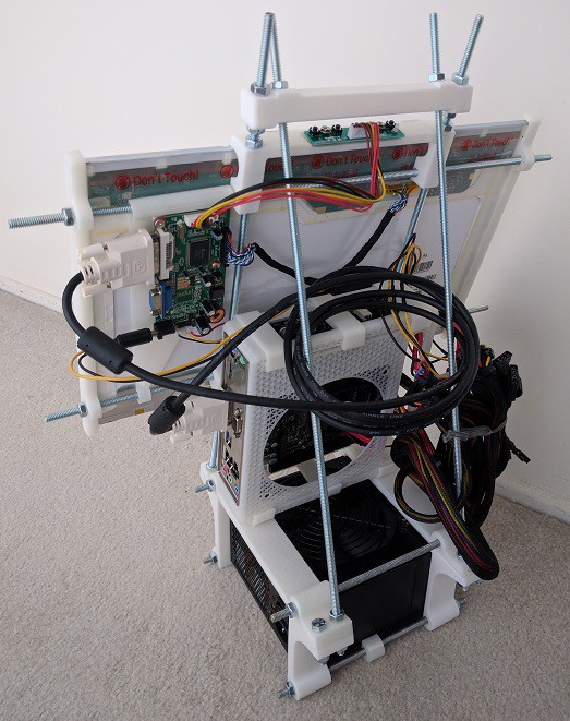
01/25/2017 at 22:43 • 0 commentsAbandoning the mess that was V1, I made a fresh start and designed easel frame 2.0. The basic shapes were dictated by:
- Full-sized ATX power supply on the bottom.
- Handle on the top
- Triangular easel frame to connect them, providing a means to support the screen and other components.
The screen and associated support structures were designed in a separate parts studio to reduce clutter.
As an incremental step to figure out integration issues, there were no provisions for other PC components in this step. The computer motherboard was still in the Mini-ITX enclosure printed earlier.
This iteration taught me that the screen support system works, and that the frame surrounding the ATX power supply should be simplified. I had thought there should be enough room to slot a full ATX board and GPU in the triangular frame, but this turned out not to be the case once wiring and mounting hardware are accounted for. So I'll need to make the triangle a little larger
And as the messy tangle of wires attest, cable management has proven to be more of a problem than I originally anticipated in this project.
![]()
-
Easel Frame 1.0
01/25/2017 at 22:23 • 0 commentsAlternate title: CAD beginner bites off more than he can chew.
In their online tutorial, Onshape promotes designing multiple parts in a single part studio, rather than one-part-per-file as in some traditional CAD software. This allows easy sharing of dimensions across interacting parts. When set up properly, updates can be automatically propagated across all the affected parts.
"Sounds great!" thought this Onshape beginner, "I'll put every component of my design in a single part studio!"
This was, in hindsight, too much to tackle all at once. Once I had tens of parts scattered across different planes of reference, I was starting to lose track of what I'm doing. Which had the (amusing in hindsight) result that I started confusing Onshape as well. Parts were sharing dimensions from other parts that coincidentally had the same dimension, but there was no real reason they had to be tied together. So when I wanted to change one of them, Onshape tried to automatically propagate changes across them all, and the results made no sense.
After spending too much time untangling this self-inflicted pain, I decided to take this as a lesson learned and start over.
Yes, one can design multiple parts in a single part studio, but the user still need to practice sensible partitioning of components in a large project.
The file was named "Easel PC" because I started with the idea of a minimalist frame inspired by a painter's canvas easel. I don't know if the concept will work so I didn't name the project "Easel PC". I'm aware that the easel-inspired design might change, but the luggable nature will not. That part's dictated by physics!
-
The Screen
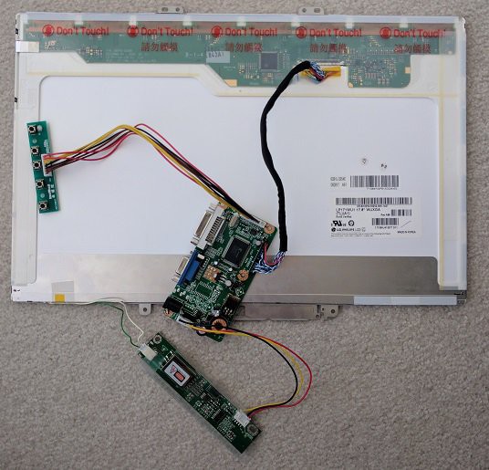
01/25/2017 at 12:07 • 0 commentsThe chassis will have an integrated screen so a screen does not have to be carried separately. The LCD panel was salvaged from my old Dell Inspiron E1705 laptop, a workhorse that eventually suffered a failure in its discrete GPU.
But before I can use the panel in my project, I need a driver board to take standard video port signal and translate to the panel's proprietary signal. Fortunately there are many vendors on eBay to provide this: search eBay for "LCD Controller Board".
After I provided all the numbers visible on the back of the panel, the vendor confirmed they can create a board for my panel. Two weeks after the PayPal payment, I received a box with the following parts:
- Main controller board, with a 12V power input port plus DVI and VGA video input ports. (In hindsight I should have ordered the version with HDMI, too.)
- A small control board with a set of buttons for brightness and contrast and other adjustments normally found on a monitor.
- A high-voltage converter board to drive the fluorescent back light.
- Wiring harnesses to connect between the boards.
Once everything was hooked up, my salvaged laptop panel became a PC monitor.
![]()
There was a minor annoyance with the board: it incorrectly reports a preferred resolution of 1280x800, so the operating system defaults to that resolution. I have to manually change over to the actual panel native resolution of 1920x1200.
And it's very obvious when the computer is sending 1280x800! The resolution scaling and interpolation of the driver board is very poor. Thankfully once I switched to the native resolution there is no further need for scaling/interpolation.
-
Feasibility test: Mini-ITX enclosure
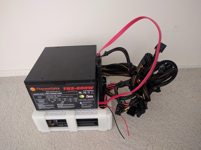
01/25/2017 at 11:38 • 0 commentsI had the idea for a custom PC chassis before, but I didn't have the tools to fabricate one until I got a 3D printer. The first order of business is to verify that my 3D printer can hit the necessary dimension requirements to print a functional PC chassis.
I started with a small Mini-ITX form factor motherboard I had on hand. The footprint of the motherboard is 17cm square, conveniently fitting within the 20cm square print area of my 3D printer. By printing a small functional enclosure for the Mini-ITX board (including the metal back plate for the ports) I gained confidence that it is possible to 3D print components for a custom PC chassis.
![]()
This small test only enclosed the motherboard and none of the other parts needed for a full PC. A fact clearly visible in the picture as exposed tangled nest of wires.
If such an enclosure would be useful to you, click the "Mini ITX enclosure" link in this project to view the OnShape public document. From the document you can export the objects to STL and print on your own 3D printer.
Luggable PC
A nominally portable ("luggable") computer chassis for commodity desktop PC components.