 Roger
Roger-
1Step 1
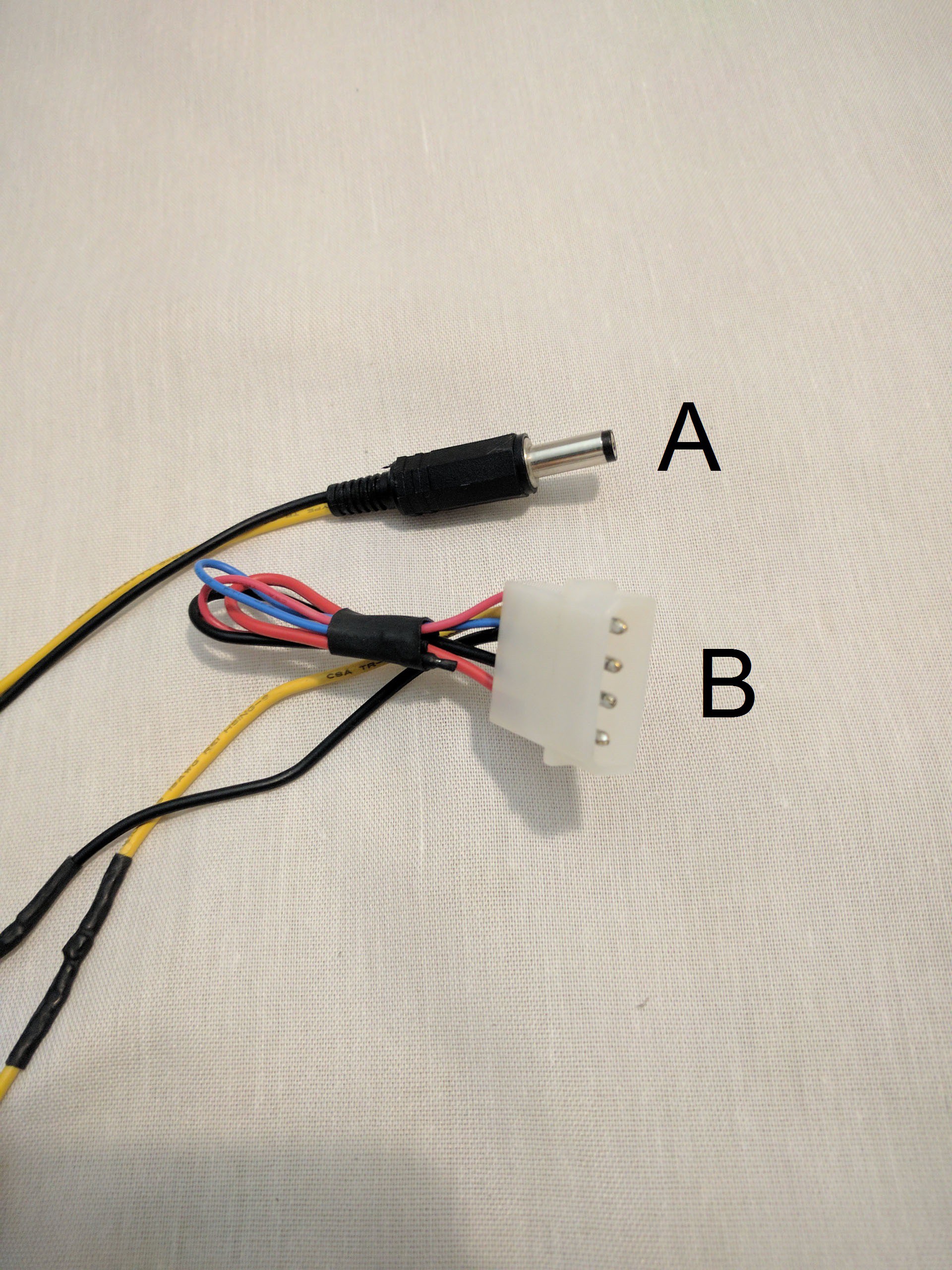
Create a power cable for the LCD panel driver board
To supply the 12V DC power required by the driver board, a cable with the appropriate barrel plug (A) is wired up to the 12V portions of a standard PC power connector (B). The 5V portion of the PC connector is sealed off with heat shrink tubing.
The length of wire required is approximately 60 cm. (~24 inches)
![]()
-
2Step 2
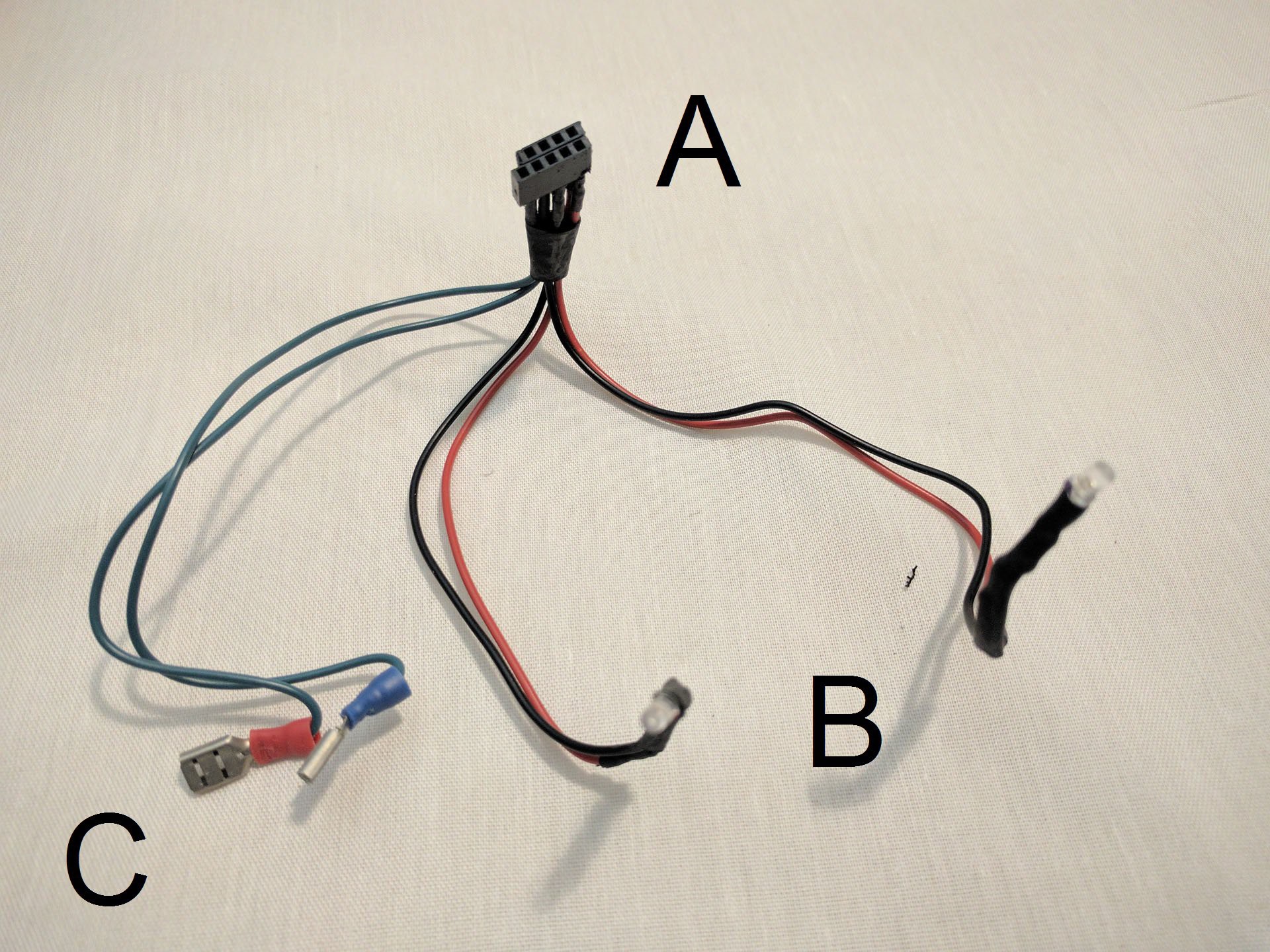
Create basic front panel controls
The standard ATX power button (momentary-on) and the two basic status LEDs (power and disk activity) are connected via a 2x5 pin 0.1" pitch plug. (A) The pin layout is specific to the motherboard used, consult the manual.
The blue power and red activity LEDs (B) are soldered directly each in series with appropriate current-limiting resistor. The power button has blade connectors so the matching female connectors are crimped on to the harness (C)
![]()
-
3Step 3
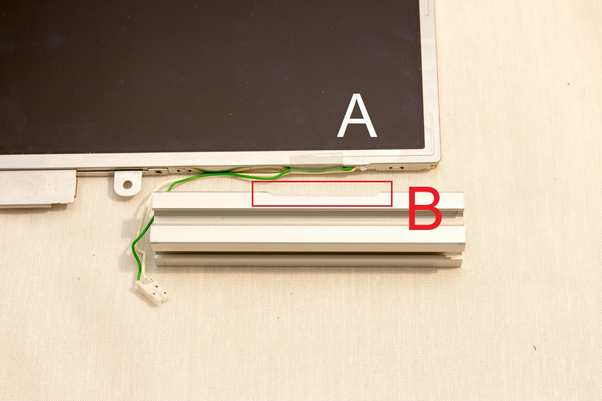
Cut slot in extrusion frame for backlight wire
The screen frame fits tightly around the perimeter of the screen. A protrusion of concern is the backlight power wire. (A) Cut a slot (B) in one of the 106.25mm extrusion pieces so the frame will not pinch the wire.
![]()
-
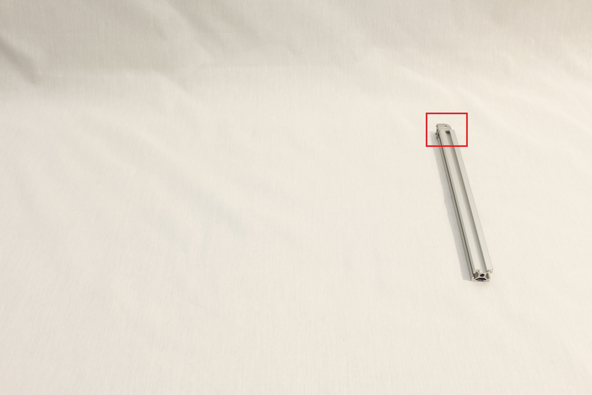
4Step 4
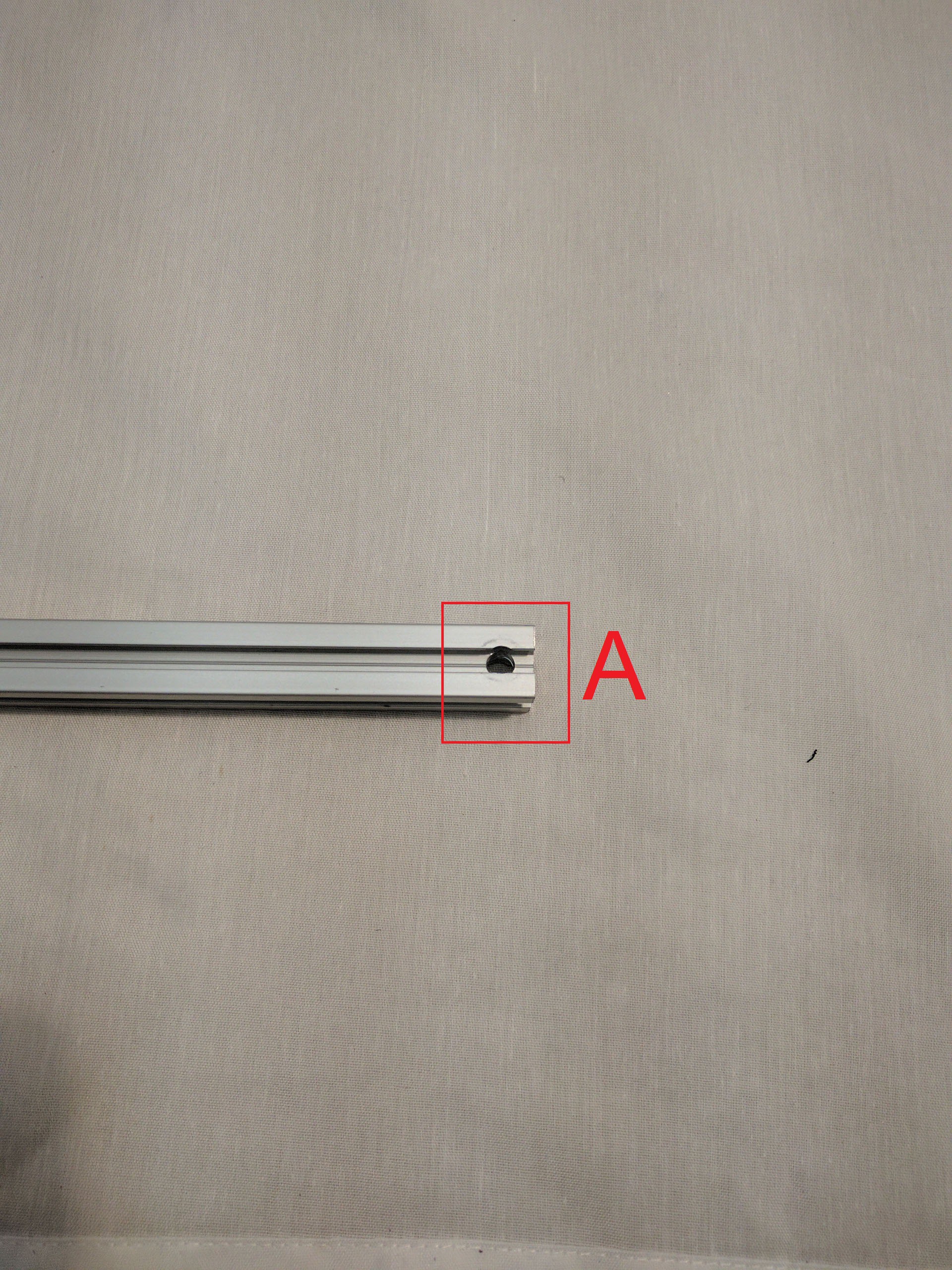
Drill hole for hinge pin
Take the 425mm extrusion and drill a 1/4" diameter hole for the hinge. The center of the hole is 10mm from the end of the extrusion and centered across the 20mm width of the extrusion. (In other words, 10mm from three sides.)
This operation is trivial with a drill press or vertical mill and a vise. If you lack these tools (as I did) you can do it by starting with a small diameter drill bit and repeat with incrementally larger drill bits, checking your position with each step up.
![]()
-
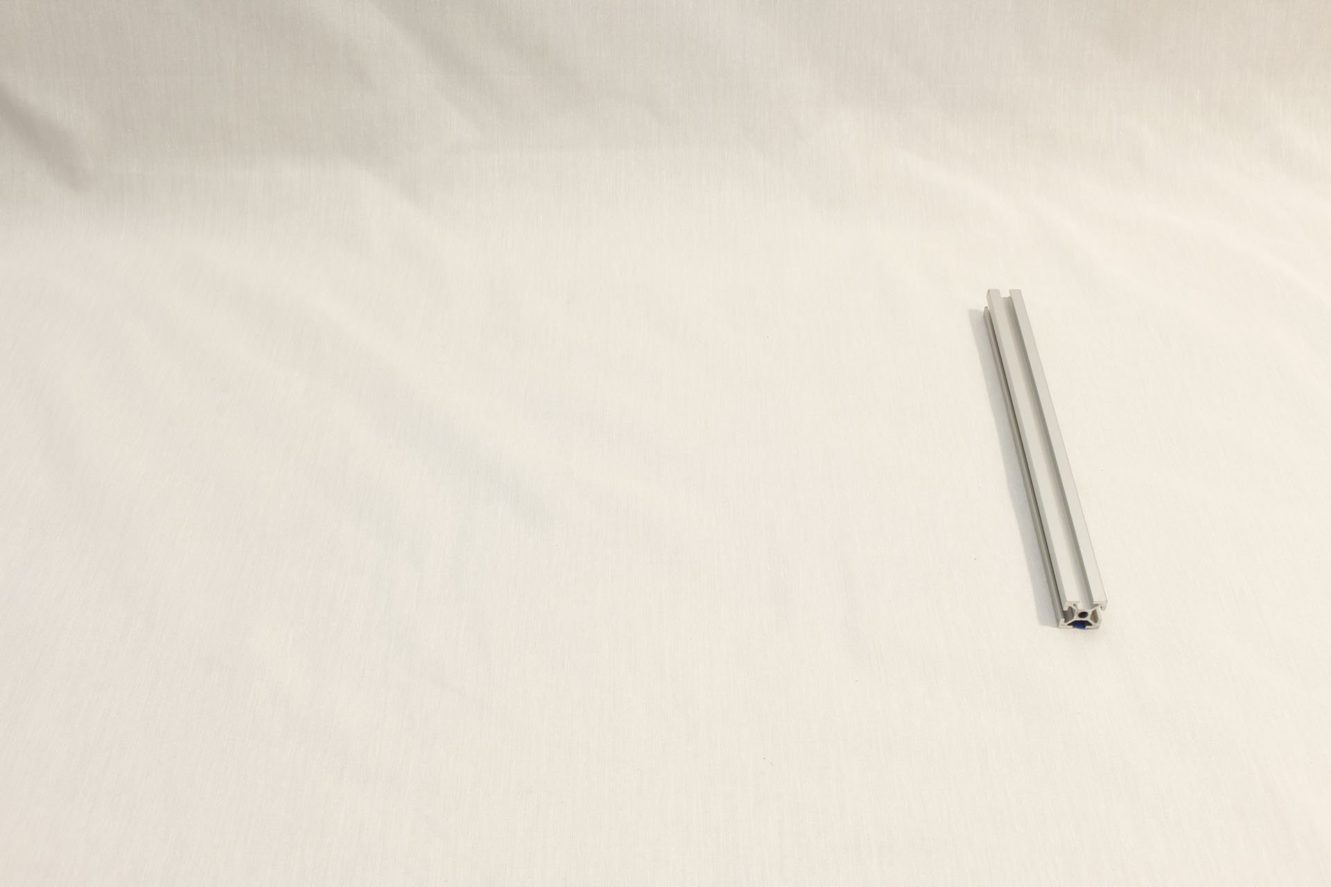
5Step 5
Begin building the screen assembly
1 x 245mm Misumi HFS5 extrusion (M5 tapped on both ends)
![]()
-
6Step 6
Attach first of three corner connectors
1 x Misumi HBLCS5 rounded corner connector
1 x M5 16mm socket screw. (Misumi CBS5-16, part of HBLCS5 package)
![]()
-
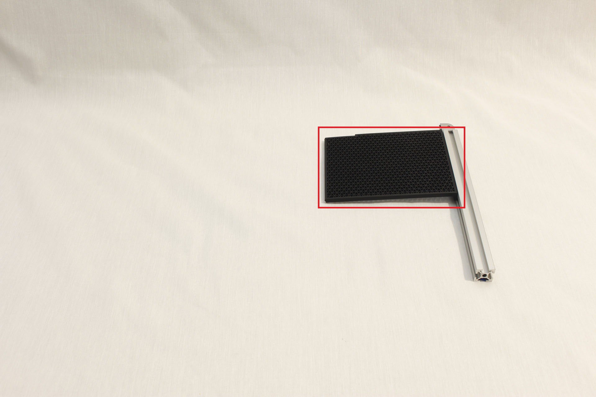
7Step 7
Attach the first 3D printed piece
Fusion 360 object path: "References"/"Screen with Extrusion Frame"/"Back Plate"/"Back Left top plate"
![]()
-
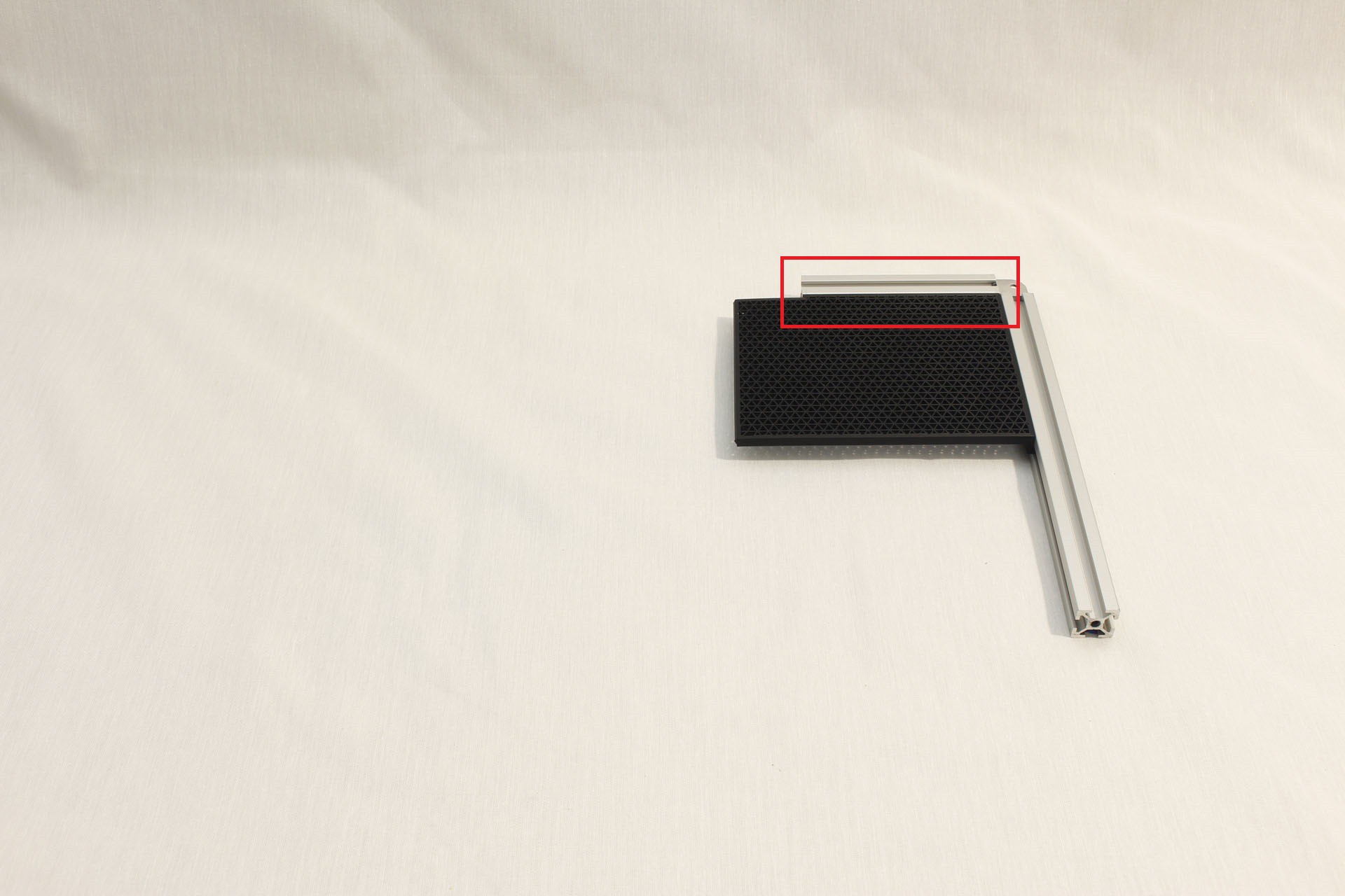
8Step 8
Complete our first corner
1 x 116.25mm Misumi HFS5 extrusion (M5 tapped both ends)
1 x M5 16mm socket screw. (Misumi CBS5-16, part of HBLCS5 package)
![]()
-
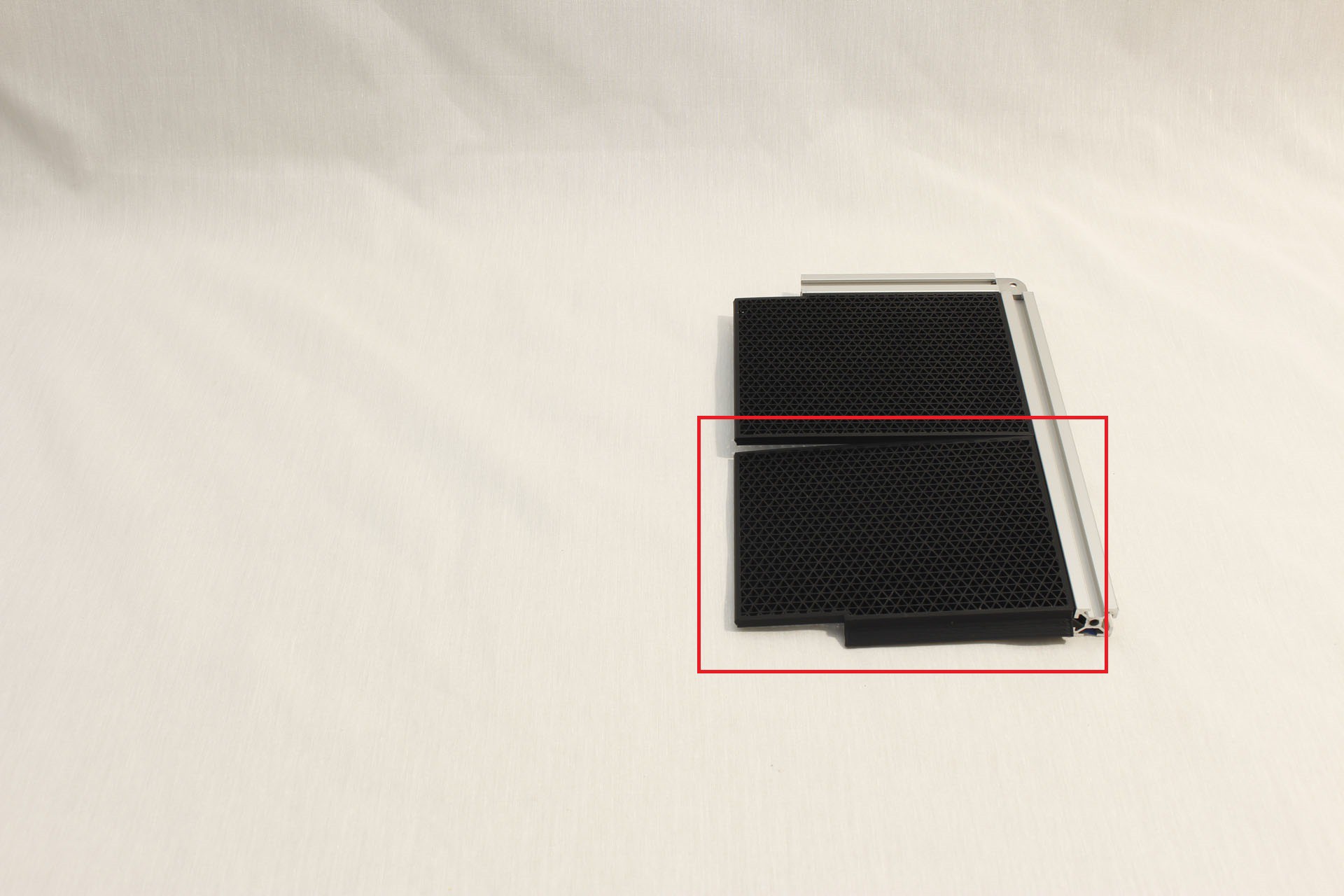
9Step 9
Add 3D printed back plate piece
Fusion 360 object path: "References"/"Screen with Extrusion Frame"/"Back Plate"/"Back Left bottom plate"
![]()
-
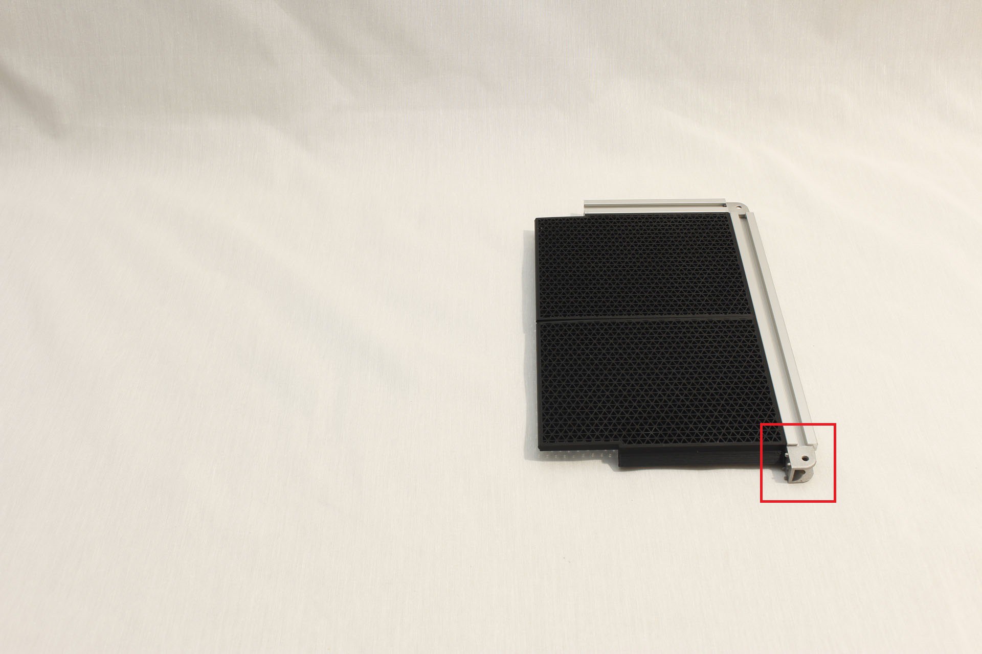
10Step 10
Attach second of three corner connectors
1 x Misumi HBLCS5 rounded corner connector
1 x M5 16mm socket screw. (Misumi CBS5-16, part of HBLCS5 package)
![]()
Luggable PC
A nominally portable ("luggable") computer chassis for commodity desktop PC components.
Discussions
Become a Hackaday.io Member
Create an account to leave a comment. Already have an account? Log In.