 Roger
Roger-
11Step 11
Complete our second corner
1 x 106.25mm Misumi HFS5 extrusion (M5 tapped both ends) This is NOT the piece we cut a notch in step 3.
1 x M5 16mm socket screw. (Misumi CBS5-16, part of HBLCS5 package)
![]()
-
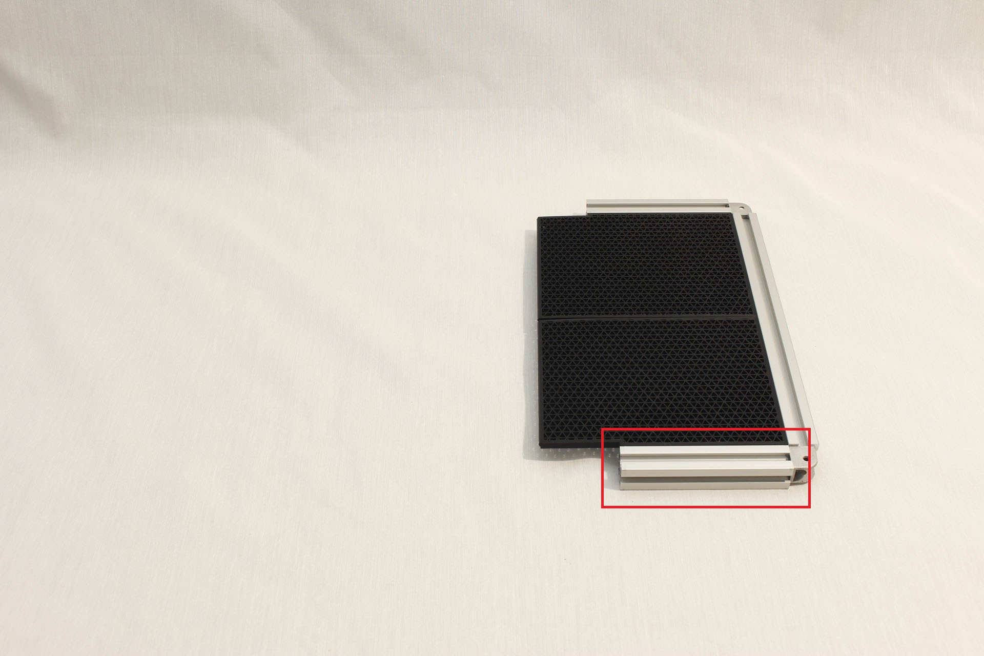
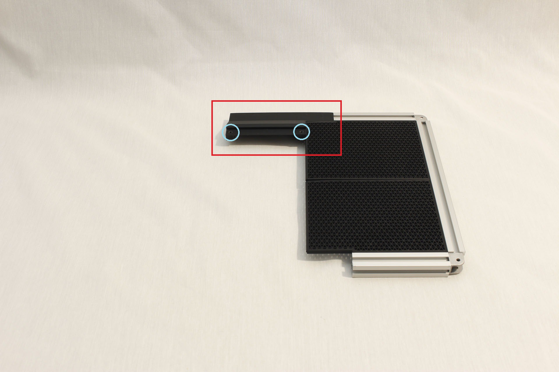
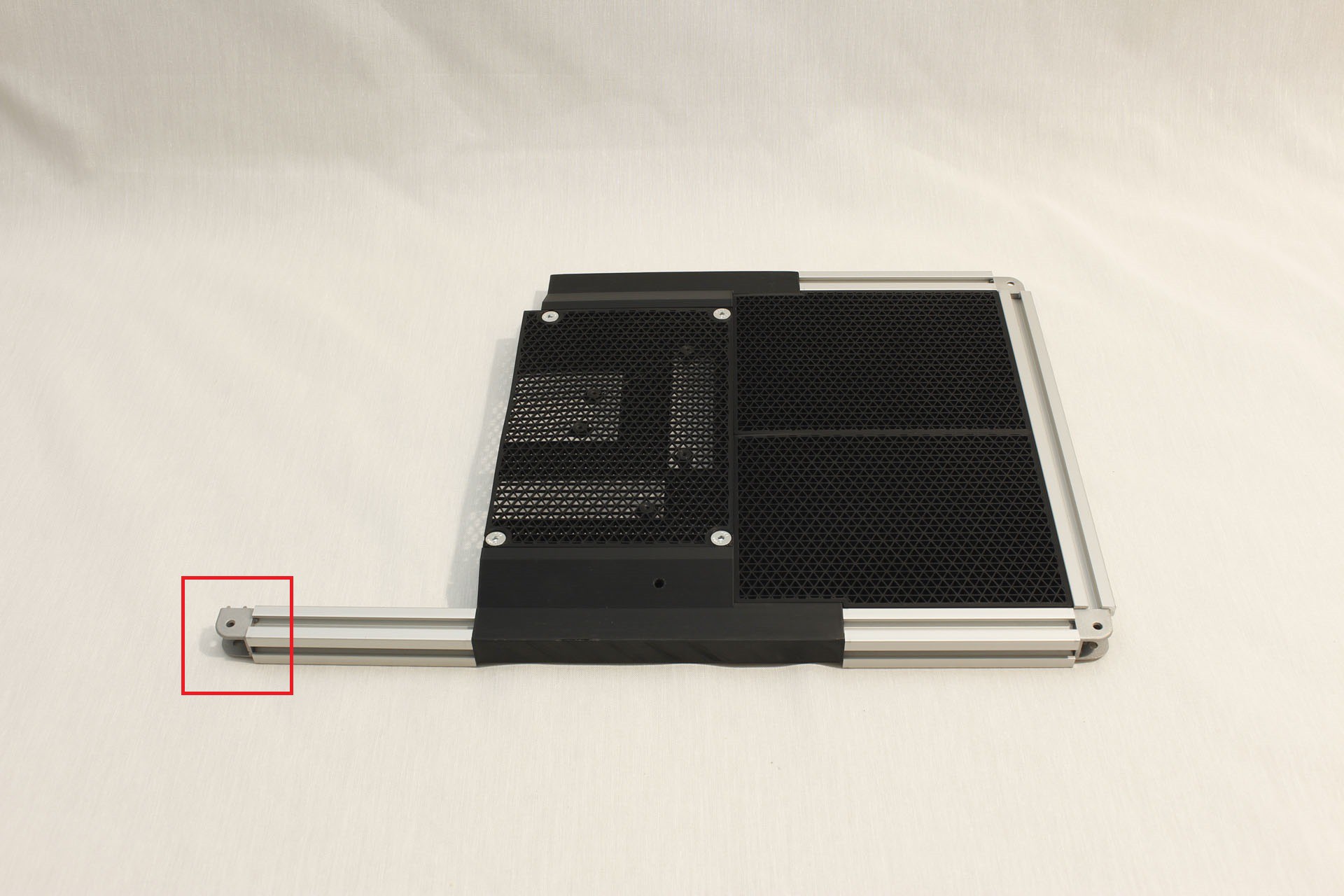
12Step 12
Attach top center piece of screen frame
Fusion 360 object path: "References"/"Screen with Extrusion Frame"/"Printed Mounts"/"Top Edge Center"
1 x M5 10mm socket head screw
Tap M5 threads in the plastic as indicated by the two blue circles.
![]()
-
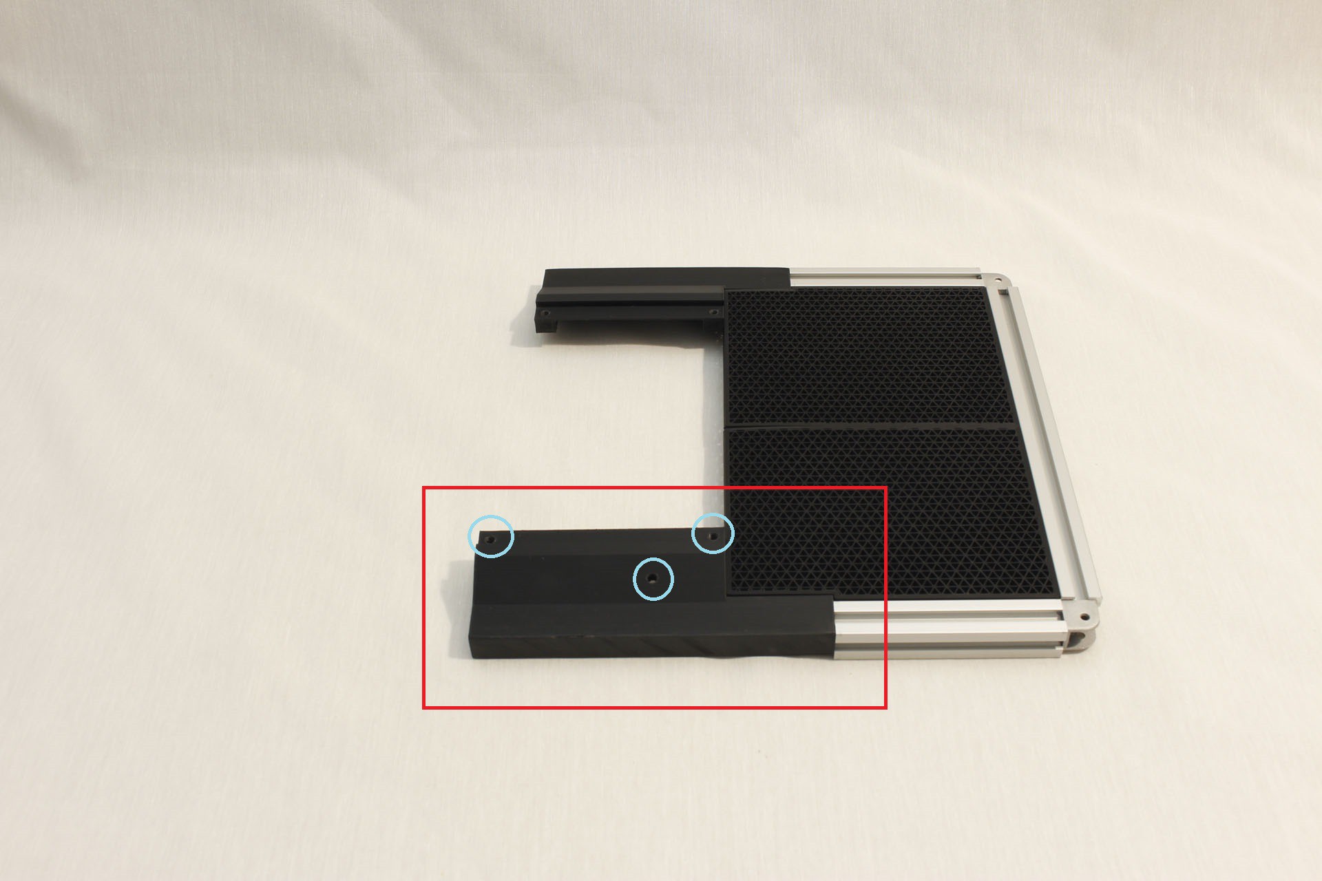
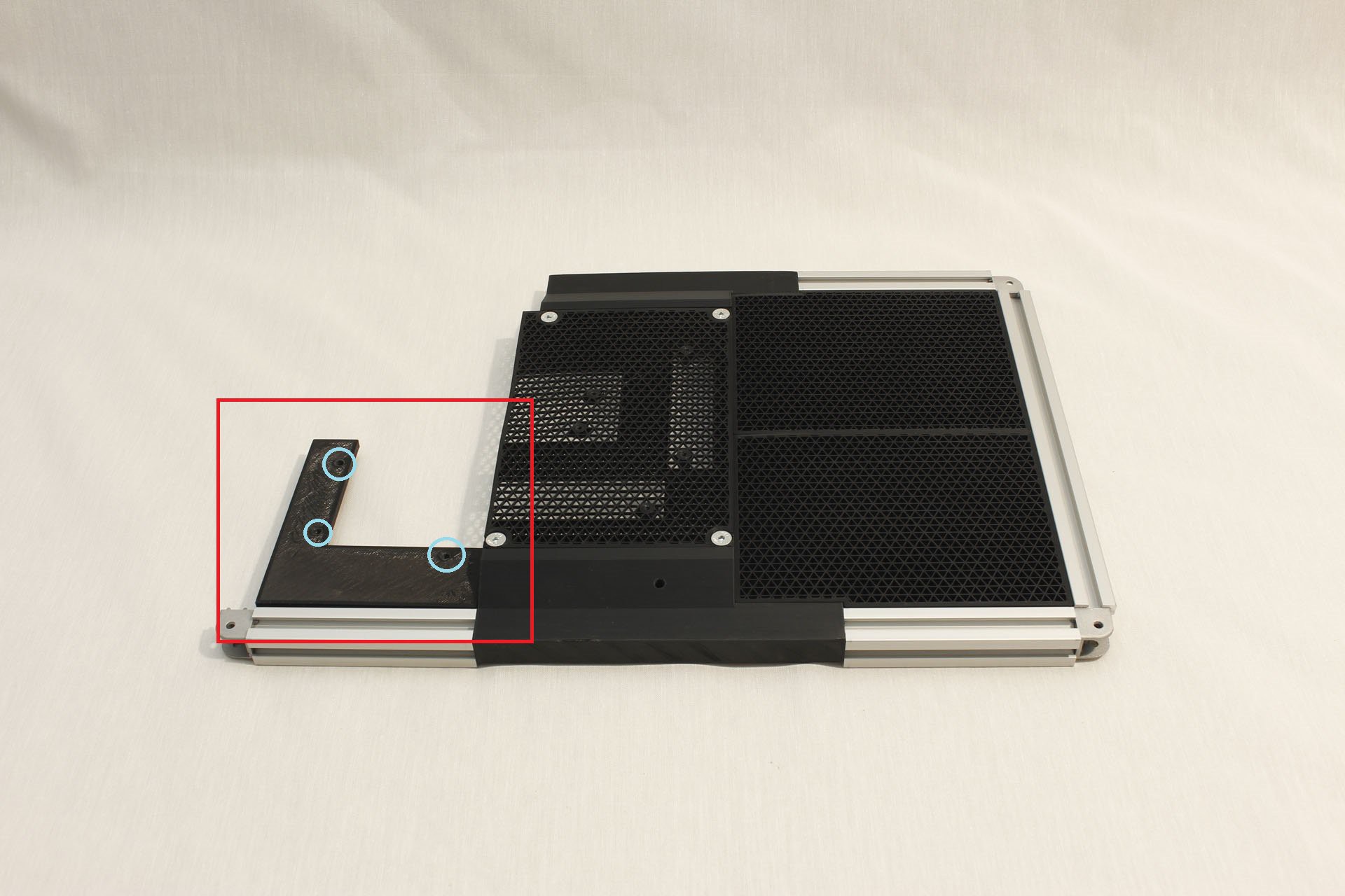
13Step 13
Attach bottom center piece of screen frame
Fusion 360 object path: "References"/"Screen with Extrusion Frame"/"Printed Mounts"/"Bottom Edge Center"
This piece carries most of the weight of the screen while open. So when 3D printing this piece, consider adjusting the settings for a stronger piece. (Thicker walls, more infill, or some combination.)
1 x M5 10mm socket head screw
Tap M5 threads in the plastic as indicated by the three blue circles.
![]()
-
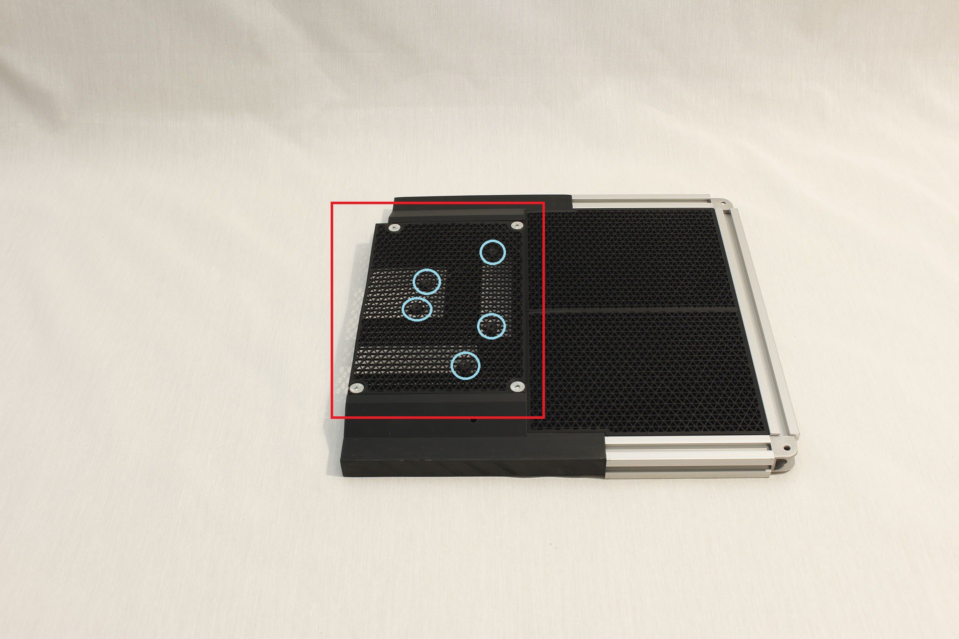
14Step 14
Attach center rear piece of screen frame
Fusion 360 object path: "References"/"Screen with Extrusion Frame"/"Back V2"/"Center plate"
This piece was printed without top or bottom layers so it is open and allows cooling air for the LCD driver board.
4 x M5 8mm flat head screws
Tap 6-32 threads in the plastic as indicated by the five blue circles.
![]()
-
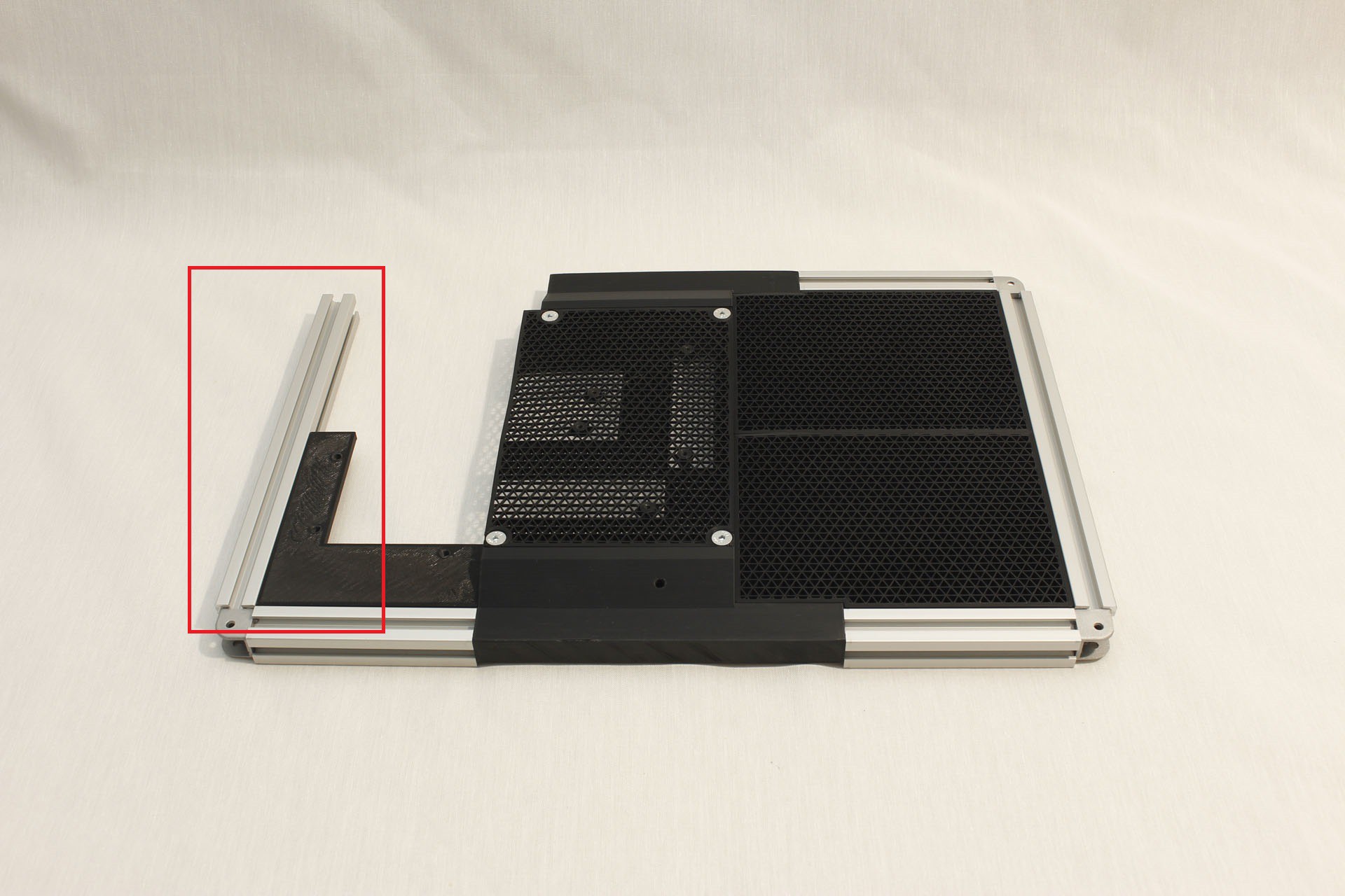
15Step 15
Continue building the frame
1 x 106.25mm Misumi HFS5 extrusion (M5 tapped both ends) This IS the piece we cut a notch in step 3.
1 x M5 10mm socket head screw
![]()
-
16Step 16
Attach the last of three corner connectors
1 x Misumi HBLCS5 rounded corner connector
1 x M5 16mm socket screw. (Misumi CBS5-16, part of HBLCS5 package)
![]()
-
17Step 17
Attach back plate component
Fusion 360 object path: "References"/"Screen with Extrusion Frame"/"Back V2"/"Bottom Right Back"
Tap M5 threads in the plastic as indicated by the three blue circles.
![]()
-
18Step 18
Attach final aluminum extrusion of screen frame
1 x 245mm Misumi HFS5 extrusion (M5 tapped both ends)
1 x M5 16mm socket screw. (Misumi CBS5-16, part of HBLCS5 package)
![]()
-
19Step 19
Attach screen hinge corner
Fusion 360 object path: "References"/"Screen with Extrusion Frame"/"Back V2"/"Top Right Back"
1 x M5 10mm socket head screw
This piece will need to handle physical stress as part of the hinge so must be printed for strength. I used 4 walls (w/ 0.4mm nozzle) 4 top and bottom layers (@0.25mm layer height) and 90% infill.
Four locations need to be tapped for M5 thread. Three for the back plate (circles) and one to attach this piece to top center (rectangle)
The location indicated by star will be fastened later as part of hinge assembly. It is OK to leave it unconnected for now.
![]()
-
20Step 20
Complete the screen frame
Fusion 360 object path: "References"/"Screen with Extrusion Frame"/"Back V2"/"Right plate"
This piece was printed without top or bottom layers so it is open and allows cooling air for the LCD driver board.
Tap 6-32 threads in the plastic as indicated by the three blue circles.
6 x M5 10mm socket head screw
![]()
Luggable PC
A nominally portable ("luggable") computer chassis for commodity desktop PC components.


Discussions
Become a Hackaday.io Member
Create an account to leave a comment. Already have an account? Log In.