The design can be greatly improved and that is why I share the CAD and not the STL. Since I consider that it is not perfect and I do not want anyone to make the mistake of printing something unpolished. I am not a designer and I have learned how to handle the program with this project. If I started from scratch with what I learned, I would change many things.
Improvements to be made:
- Apply tolerances in the joints. Due to the size of my printer I had to cut several pieces. When putting them together I have had many fitting problems.
- Draw and design the HDMI wiring and power supply of the components. I have had to modify and change cables due to lack of space.
- I would add a metal cylinder/tube for the plunger. Now I have plastic rubbing against plastic and it is not ideal.
- I would change the layout design of the electronic cards. Something more robust.
- The playfield screen has a frame on one side and does not allow it to be centered correctly.
-With a new playfield, I would change the classic pinball design and place the screen flush with the furniture. Most of the tables already emulate the height they had and would have had more inches of screen.
-Design the wiring and common points of voltages and masses. Space is very limited and it turned out too dirty for my taste. I hope I don't have to rewire due to some error 😁.
-Except for the plunger, which has nuts inserted into the plastic, the rest is screwed onto a thread printed on the same plastic. If I were to design again I would use nut grafts on all joints. I would also reduce them, you don't need as many screws
2
Step 2
Micro Virtual Pinball Peripheral:
Micro Pinball concept:
The origin of creating it in 3D is because at home I don't have space for a mini or normal one. So I thought about making a peripheral for a laptop I already had. The problem is that the laptop only has one HDMI output and I wanted to use two more for the Backglass and the DMD. I was testing several accessories that connected to USB had two HDMIs. After several attempts (bless AMAZON and their return policy), I got it with this one:
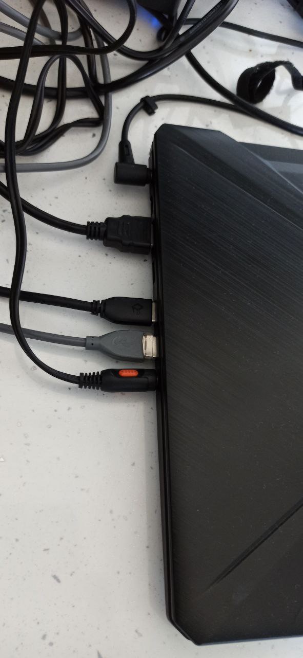
The pinball has two USB inputs (1 for the KL25Z and 1 for the HDMI HUB), an HDMI for the playfield and an audio input for the audio amplifier.
It has a power input where I connect an F.A. external 12V like the one used in laptops.
For the dimensions of the pinball, use these proportions, scaling to the size of my screens.
4
Step 4
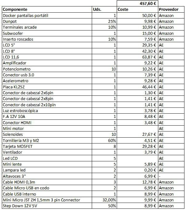
As for the economic part, in the list you can check the details of the investment
5
Step 5
For the preparation and knowledge of everything related, there is a guide that has everything more than detailed. It is more than basic to read it and have it as a guide
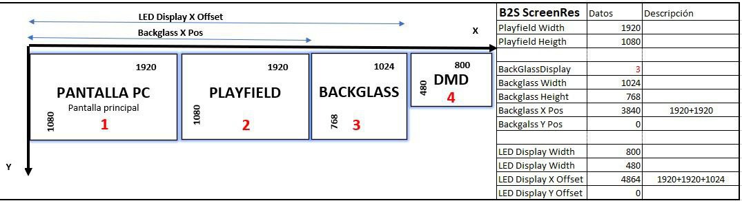
I don't want to go into technical configuration details, because that's what the guide is for and I would never finish this report. But due to the peculiarity of the project, I share my screen configuration
6
Step 6
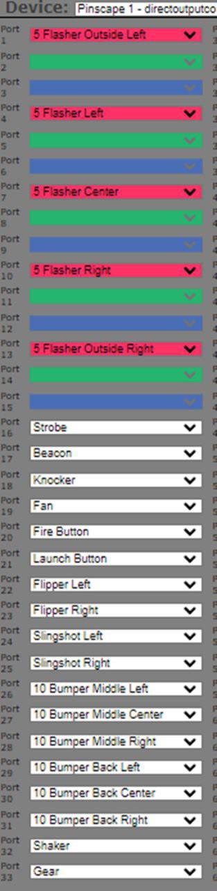
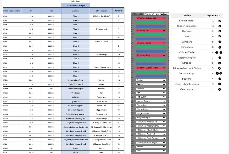
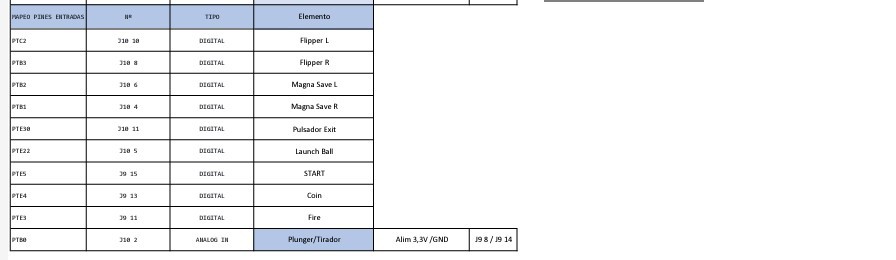
As for the "toys", I add the list according to DOF configuration
Micro Virtual Pinball Peripheral:
At first I had the intention of adding solenoids to imitate the sounds of the different components of the tables, but some MOSFET cards failed and the wiring was also becoming complicated due to lack of organization and space. My hands are not precisely watchmakers'
Even so, I have: 5 RGB, strobe, beacon (beacons because I didn't find such small sirens), Knocker (solenoid inside the Backglass), Fan (Fan for wind effects), Fire button, Launch button (the lights interact with some phases of the game).
7
Step 7
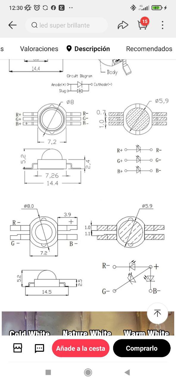
For all the wiring, I add the pin assignment on the KL25Z and the schematic I used.
See the files in the project
8
Step 8
1. HDMI PLAYFIELD
2. USB DOCKER HDMI
3. USB KL25Z
4. INPUT SOUND MINI JACK 3,5
9
Step 9
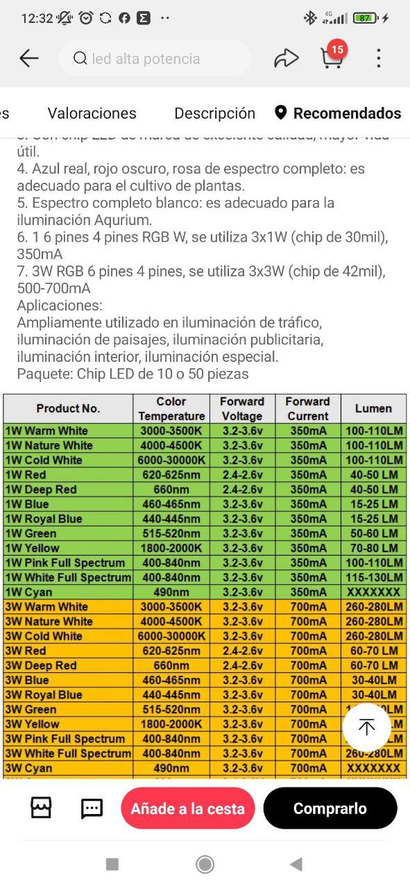
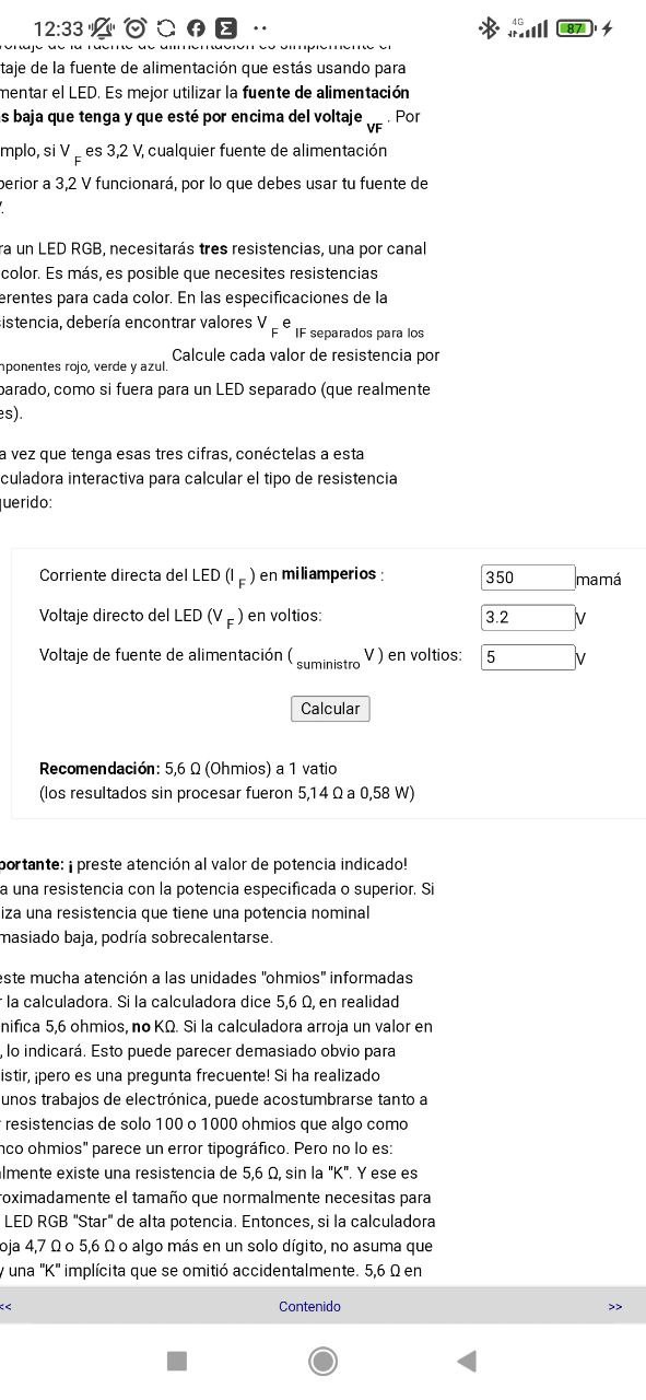
Micro Virtual Pinball Peripheral: The calculation of the resistance can be done by entering the work values on the pinup website
 SrBlonde
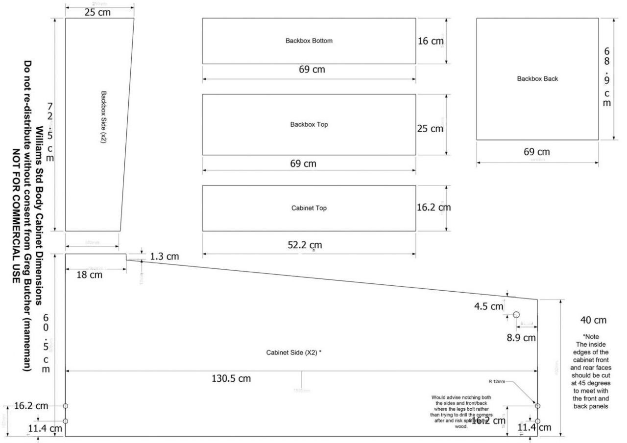
Discussions
Become a Hackaday.io Member
Create an account to leave a comment. Already have an account? Log In.