-
1PCB ASSEMBLY
![]()
![]()
![]()
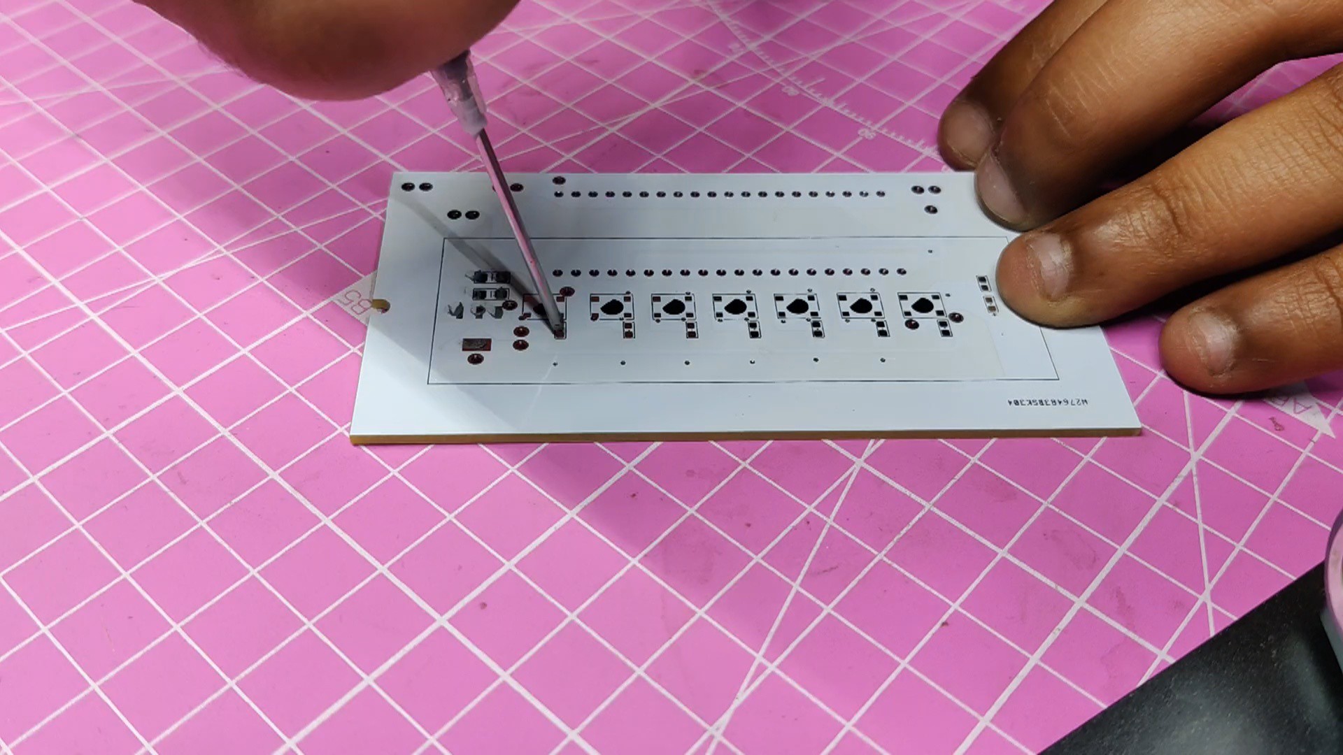
- Using a solder paste dispensing needle, we first add solder paste to each component pad individually to begin the PCB assembly process. In this instance, we are using standard 37/63 solder paste.
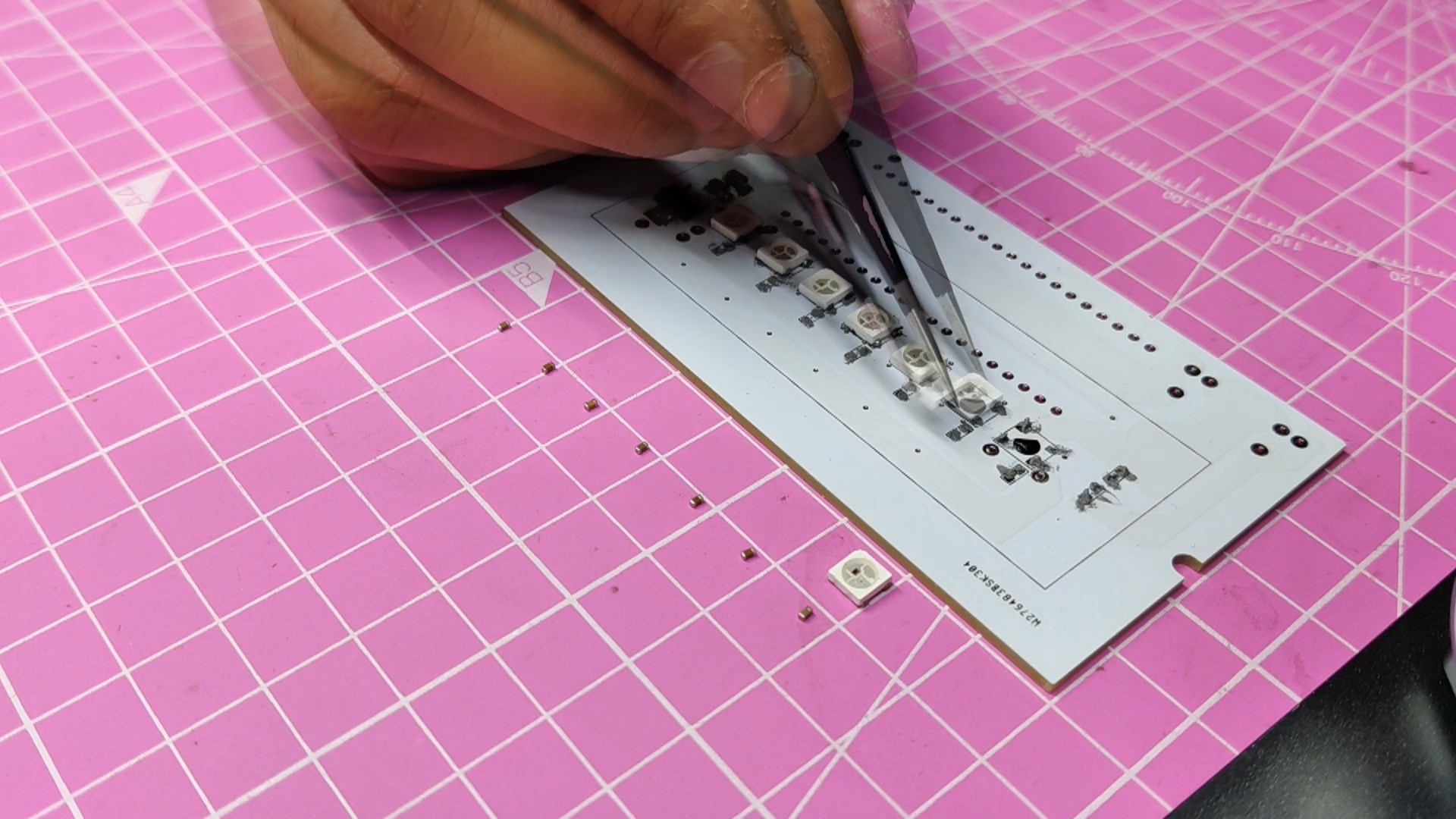
- Next, we pick and place all the SMD components in their places on the PCB using an ESD tweezer.
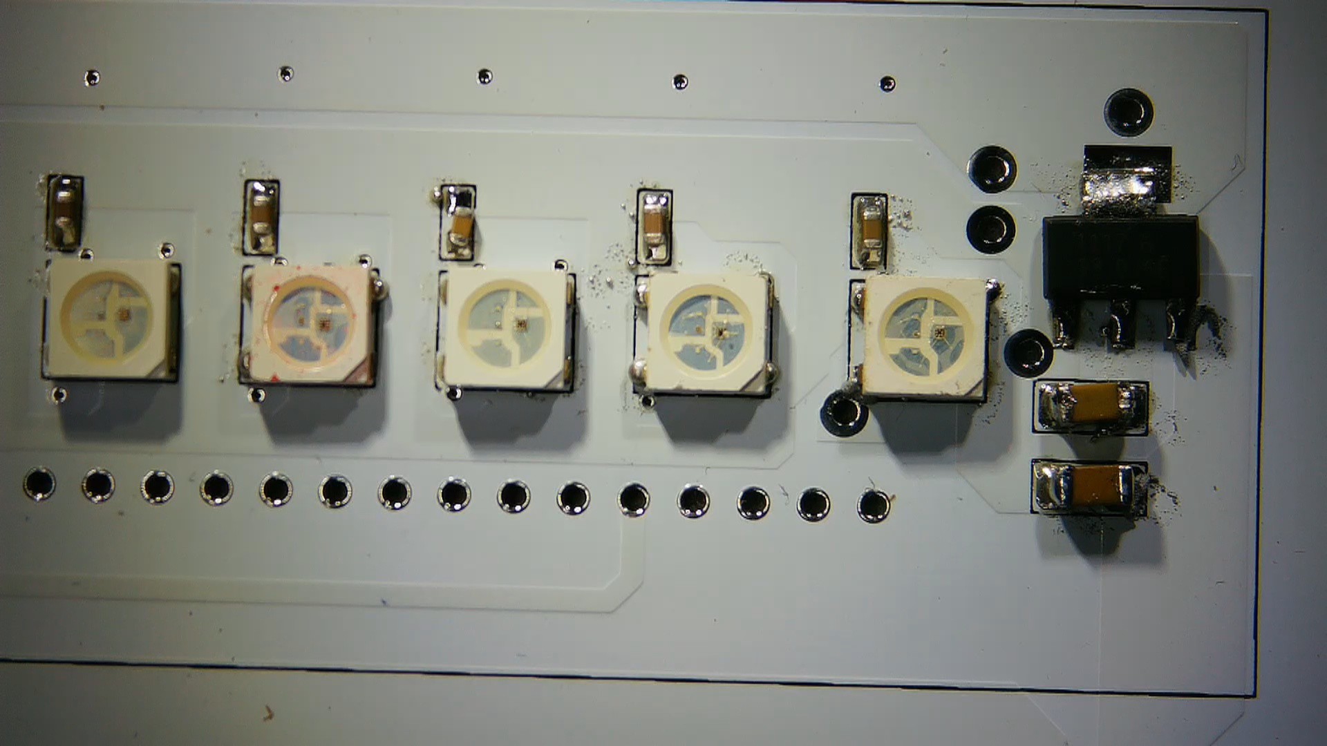
- With extreme caution, we lifted the complete circuit board and placed it on the SMT hotplate, which increases the PCB's temperature to the point at which the solder paste melts and all of the components are connected to their pads.
- Next, we add all the THT components, which include the header pin, Raspberry Pi Pico, and CON2 JST Connectors, to their locations and then solder their pads using a soldering iron.
THE PCB IS NOW READY!
-
2Audio Module and Sound Hardware
![]()
![]()
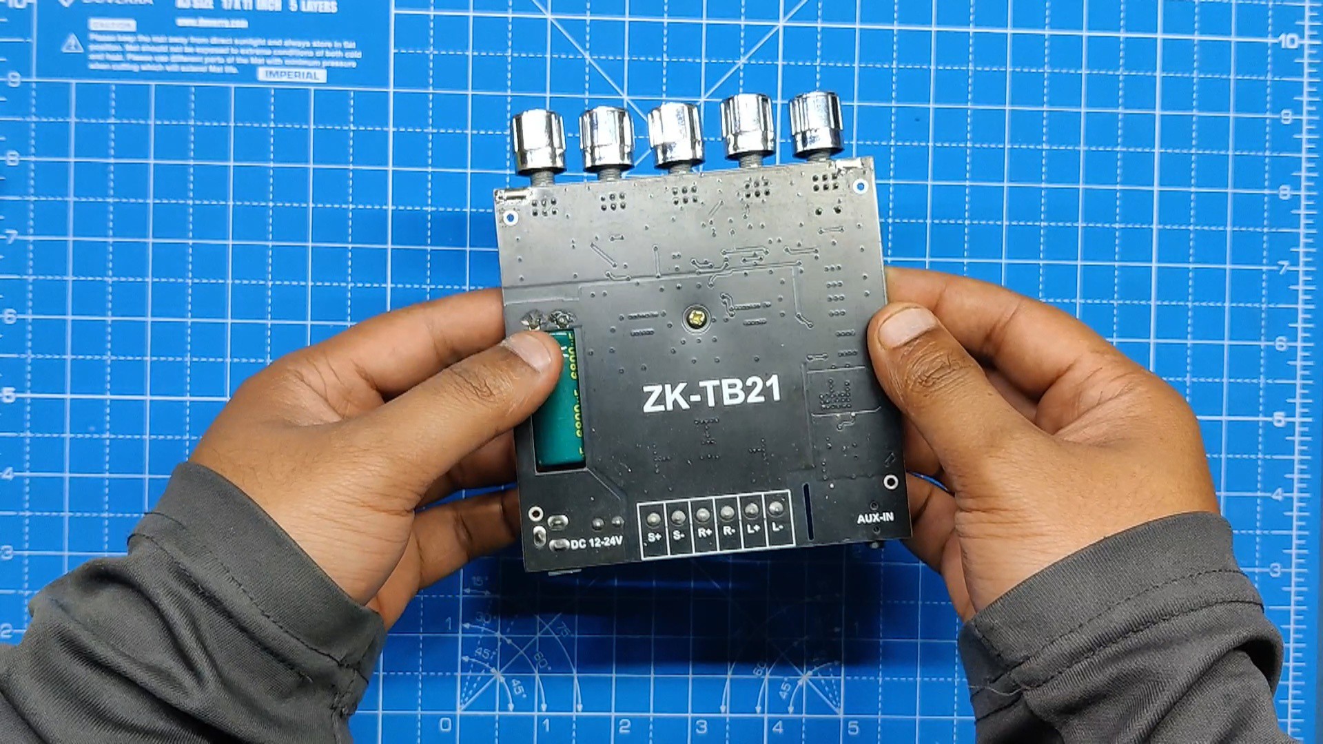
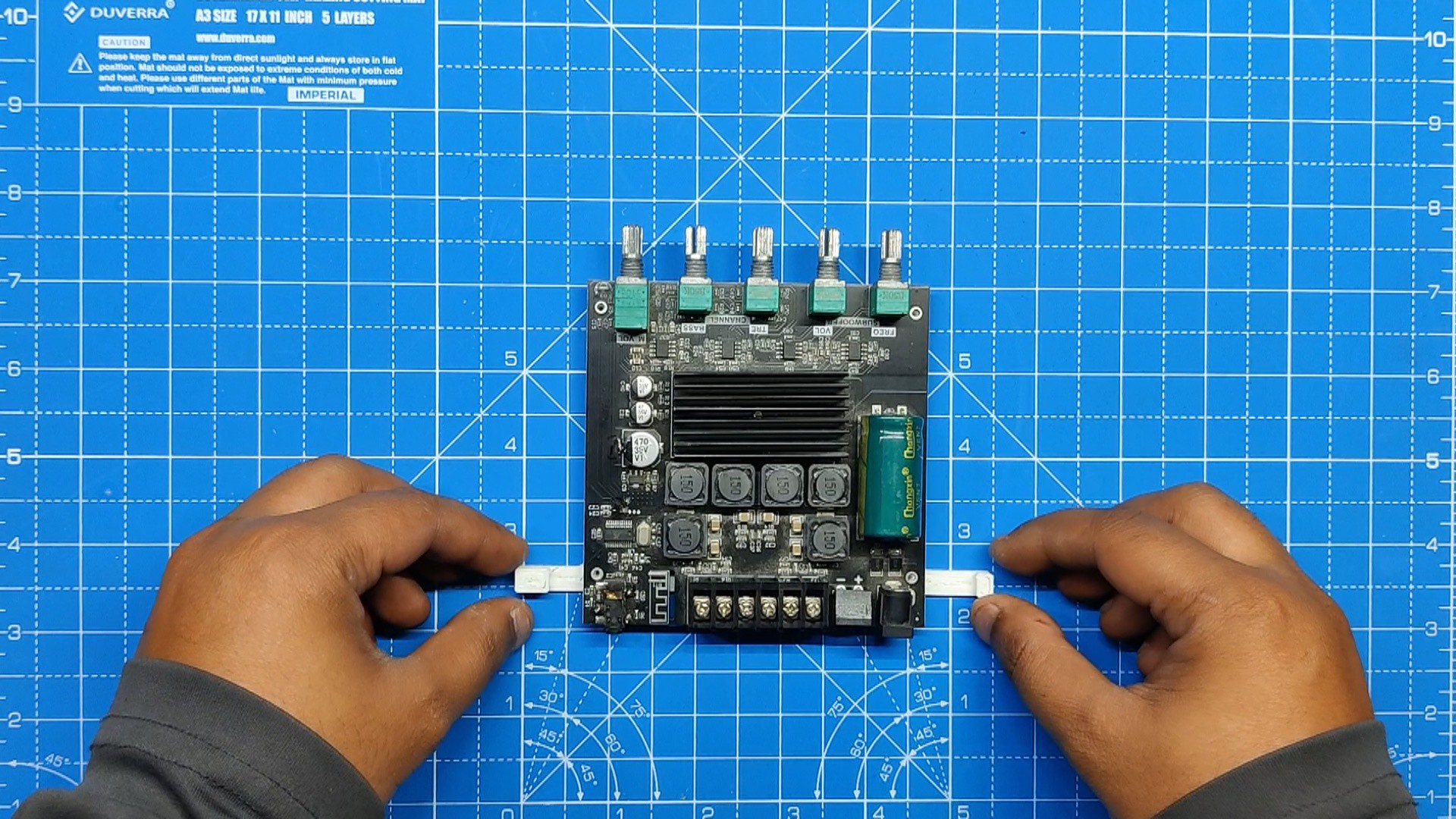
The ZK-TB21 is being used in this project, which is a 2.1-channel audio power amplifier based around the TPA3116D2 power amplifier chip.
TPA3116D2 is a Class D stereo amplifier that can drive speakers up to 100 watts. To drive two 100-watt speakers, the ZK-TB21 utilizes two of these TPA3116D2 chips. one for the left and right speakers, and one for the subwoofer
Also, there's a Bluetooth audio IC on this board, which lets us connect with this board for audio streaming.
Technical Specifications of Module
- Product name: 2.1-channel Bluetooth audio power amplifier module
- Product model: ZK-TB21
- Bluetooth version: 5.0 (unobstructed, 10 meters)
- Input sensitivity: 500 mV
- Input method: AUX + Bluetooth
- Number of channels: 2.1 channels
- Power amplifier chip: TPA3116D2 (with AM interference suppression function)
- Adaptable power supply: DC12~24V / 5A or more (over-voltage, output power setting)
- Adapt to speakers: 20~100 W, 4~8.
- Output power: 50W for left and right channels
- Subwoofer 100W
- Protection mechanisms: overvoltage, under voltage, overvoltage, DC detection, short circuit protection
- Product size: 120mm * 100mm * 20mm
- Product weight: about 256g (including packaging)
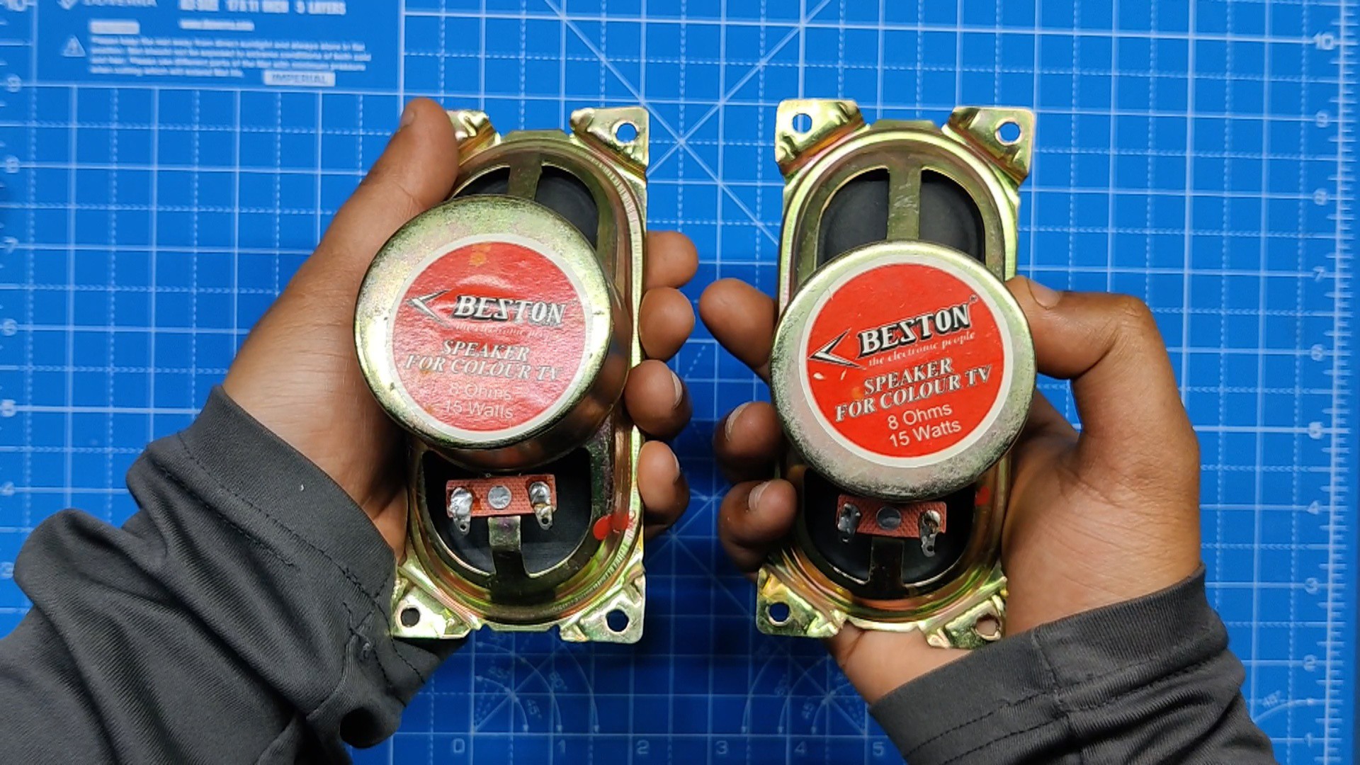
As for sound, we are using two 8-Ohm, 15-W speakers paired with the ZK-TB21 Audio Module.
-
3Speaker Assembly
![]()
![]()
![]()
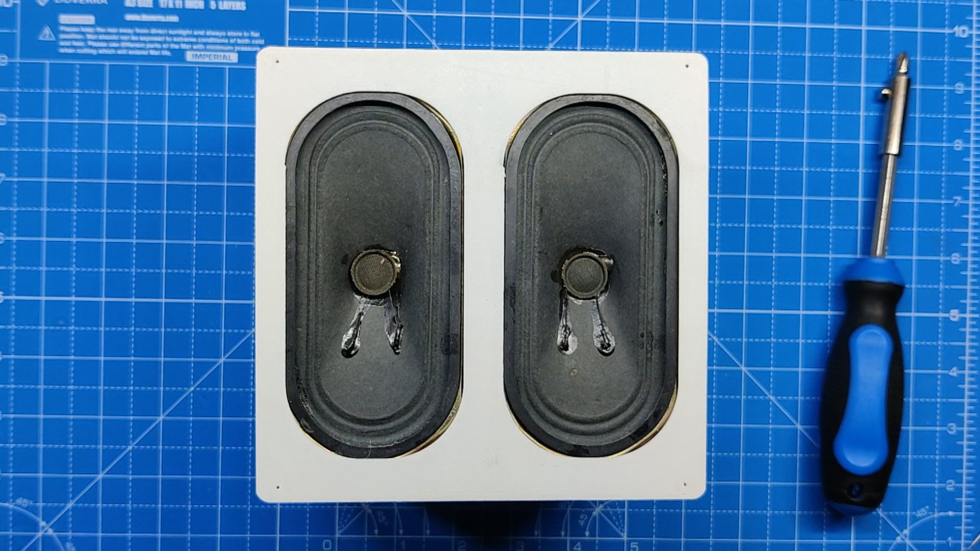
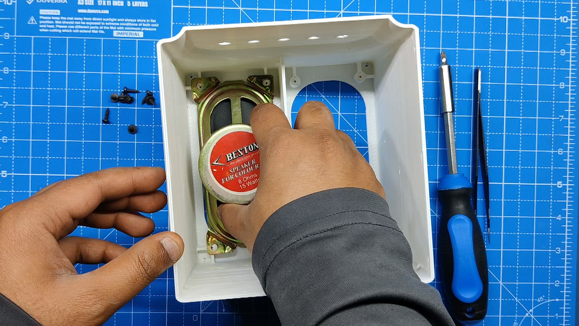
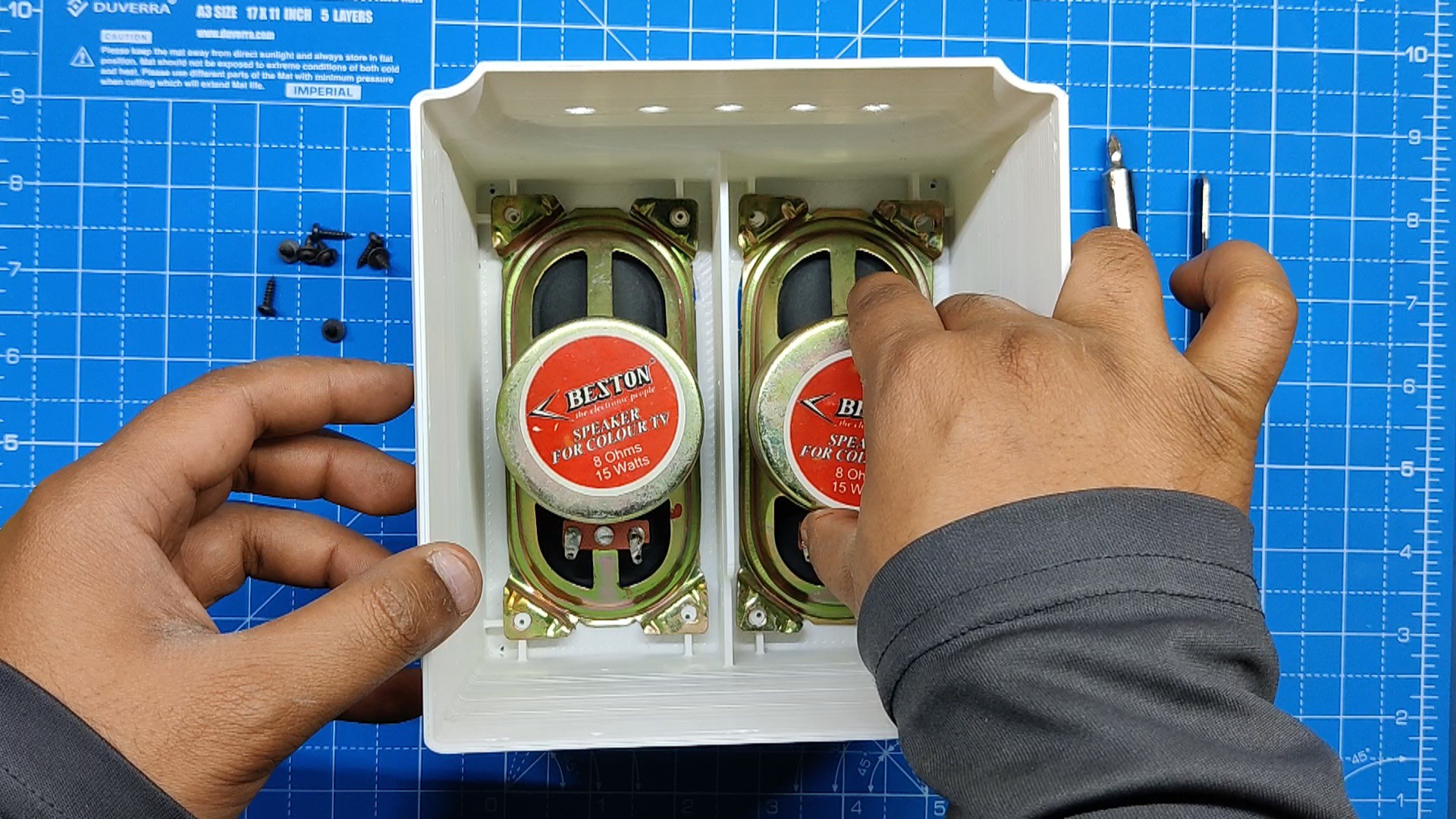
First, we assemble the speakers, which was quite easy.
We take the two 15W speakers and install them inside the Main Base.
Eight M2 screws were used to permanently fix the speakers after they were positioned inside the main base in their designated spots.
-
4Adding the Audio Module inside Base
![]()
![]()
![]()
![]()
![]()
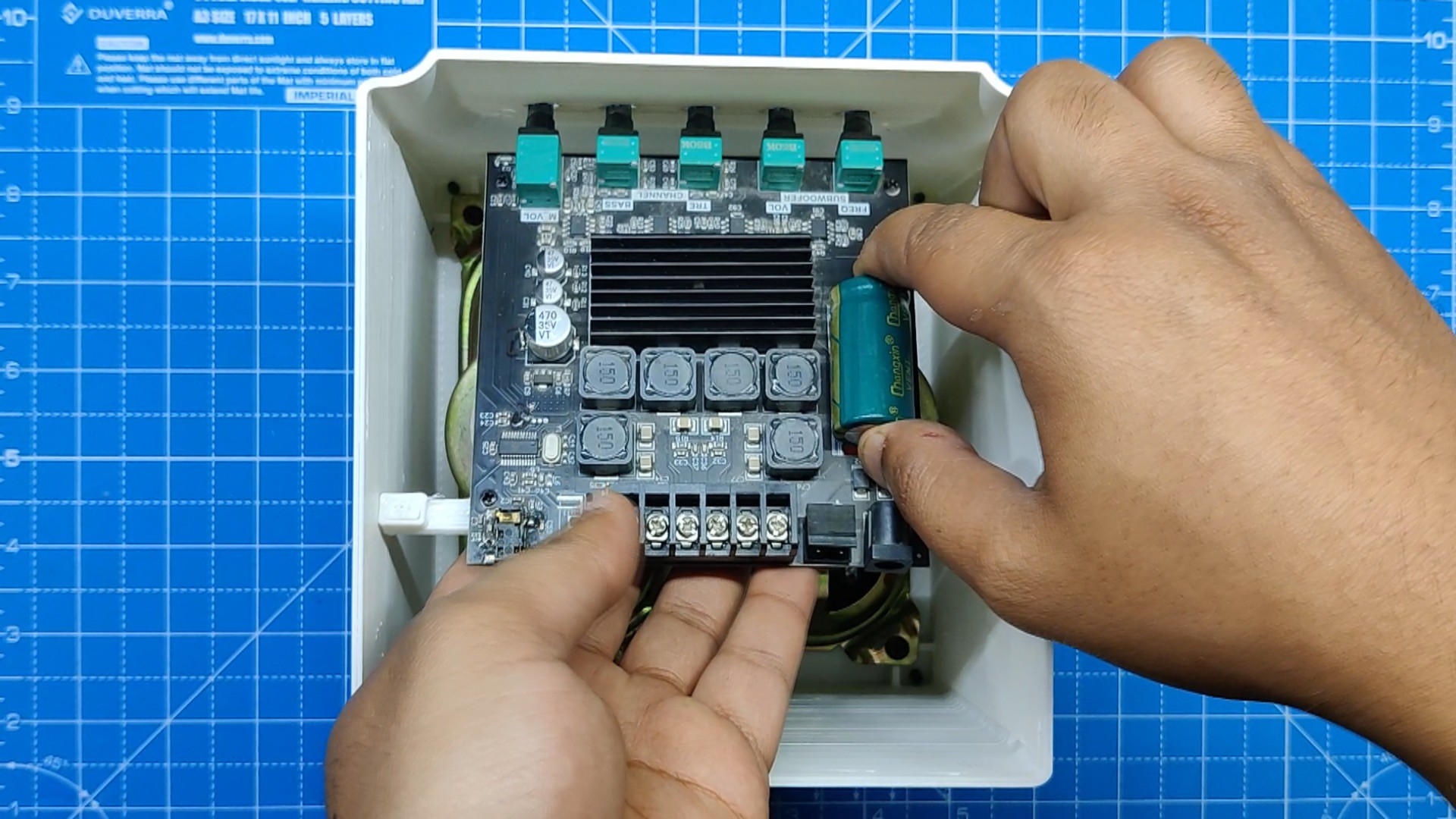
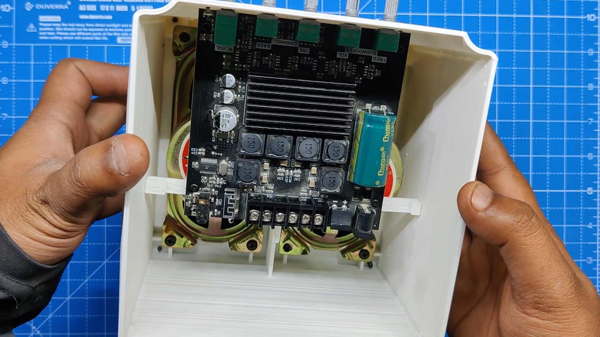
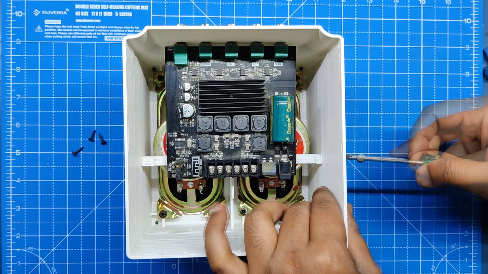
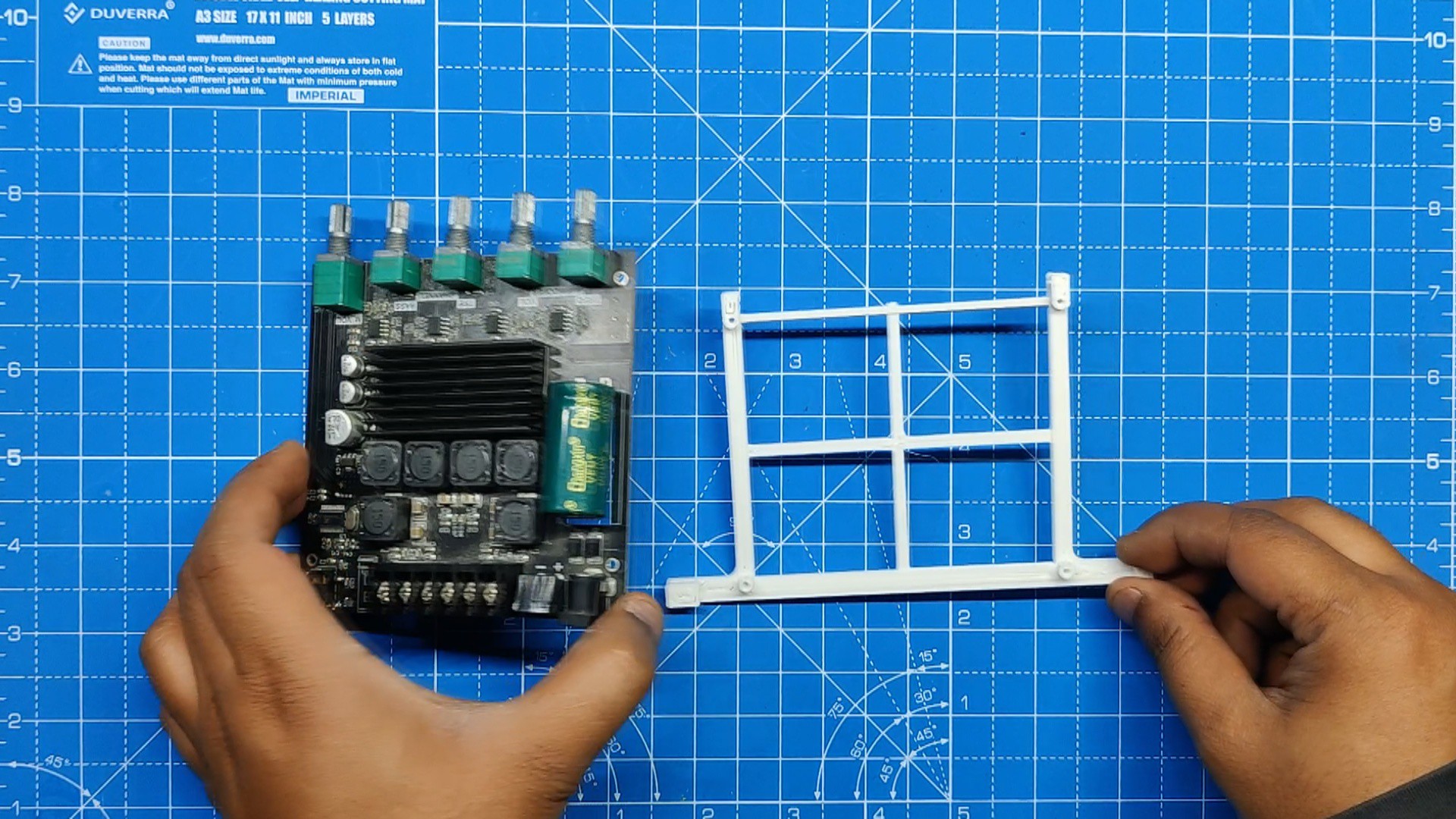
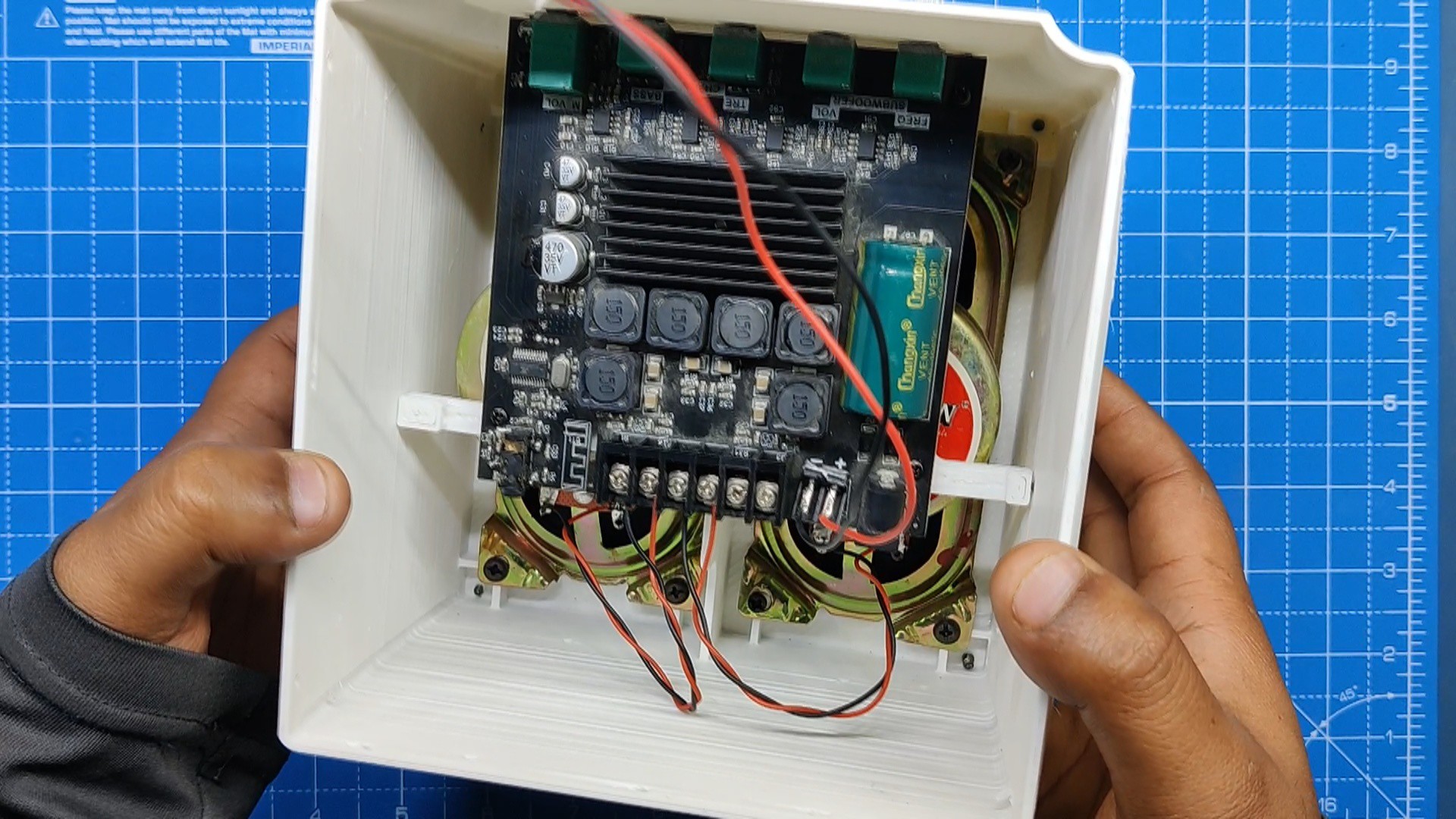
As explained earlier in the Design Process, we have modeled an Audio Module Holder part that is mounted with the Audio Module so that the entire assembly can be placed inside the Speaker body vertically.
- The Audio Module is positioned atop the holder component, and four M2 screws are used to secure both of them in place.
- Next, we take the whole assembly and slide the audio module into its place.
- At last, we use four M2 screws and secure the audio module holder assembly in its place.
-
5Wiring
![]()
![]()
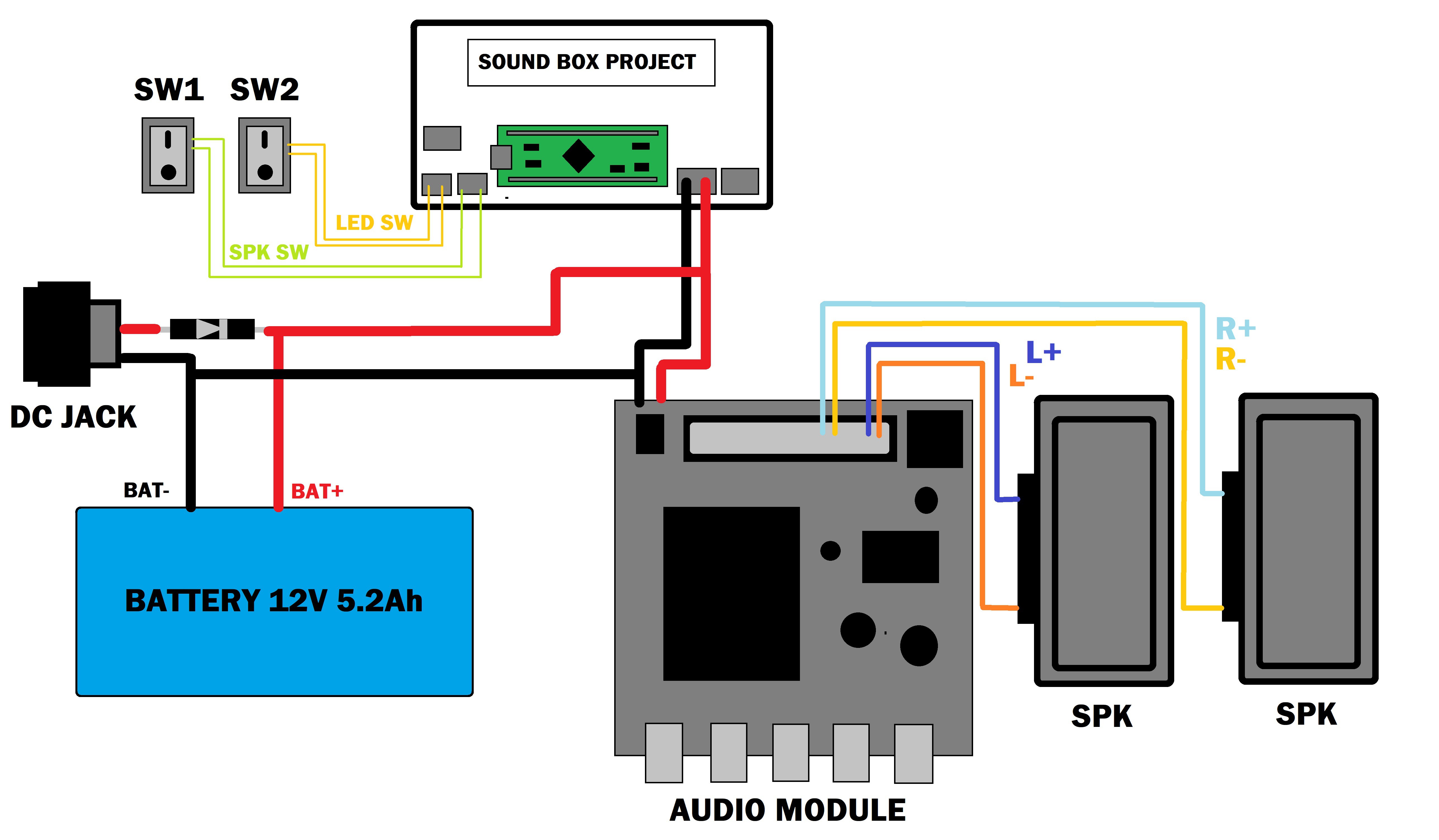
As for the wiring process, we connected the positive and negative terminals of both speakers with the audio module's Left and Right Speaker connectors.
Next, we added a CON2 Wire harness with the audio module's input connector, this wire harness will be connected to the RGB LED Board's JST Connector for powering the Audio Module.
-
6Back Lid Assembly
![]()
![]()
![]()
![]()
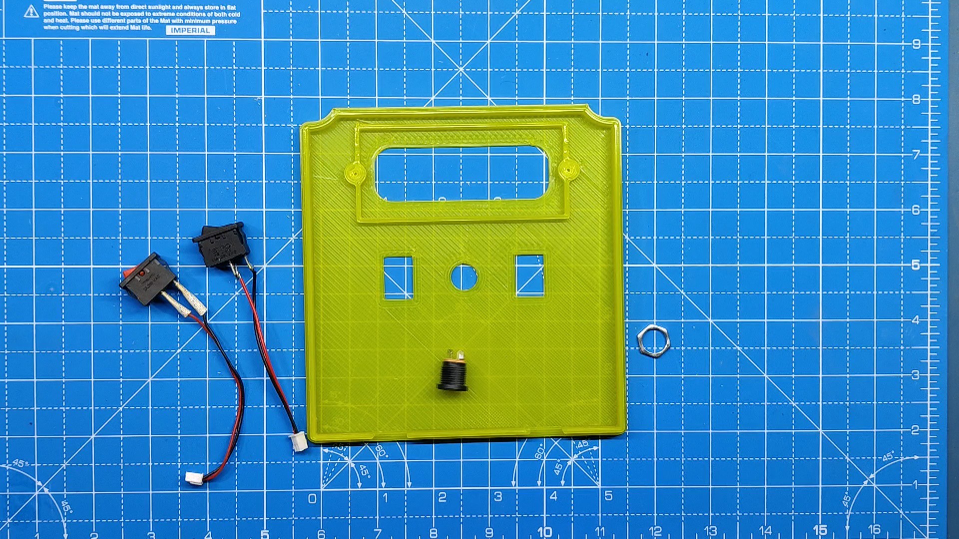
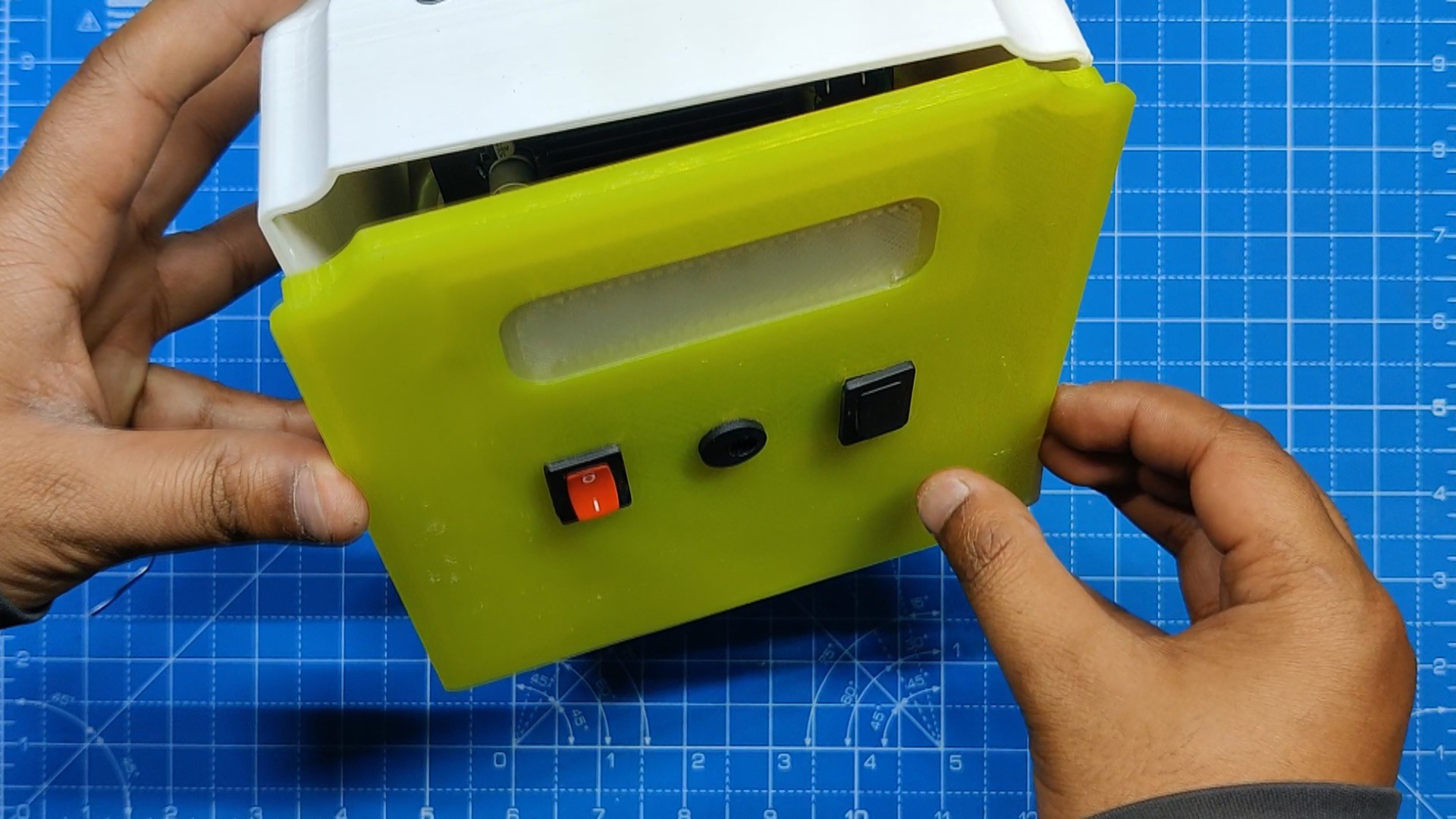
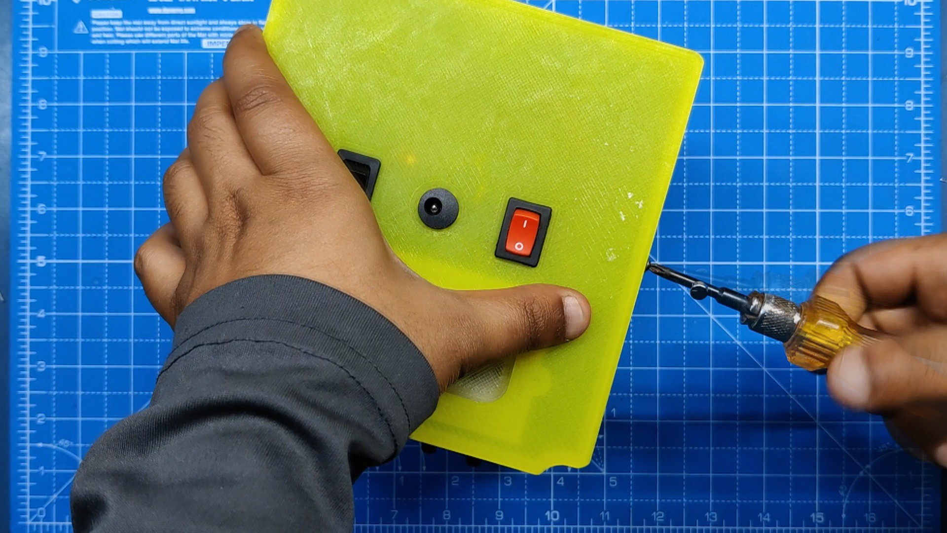
- Before beginning the Back Lid assembly process, we gather all of the remaining components, which include one DC barrel jack and two rocker switches.
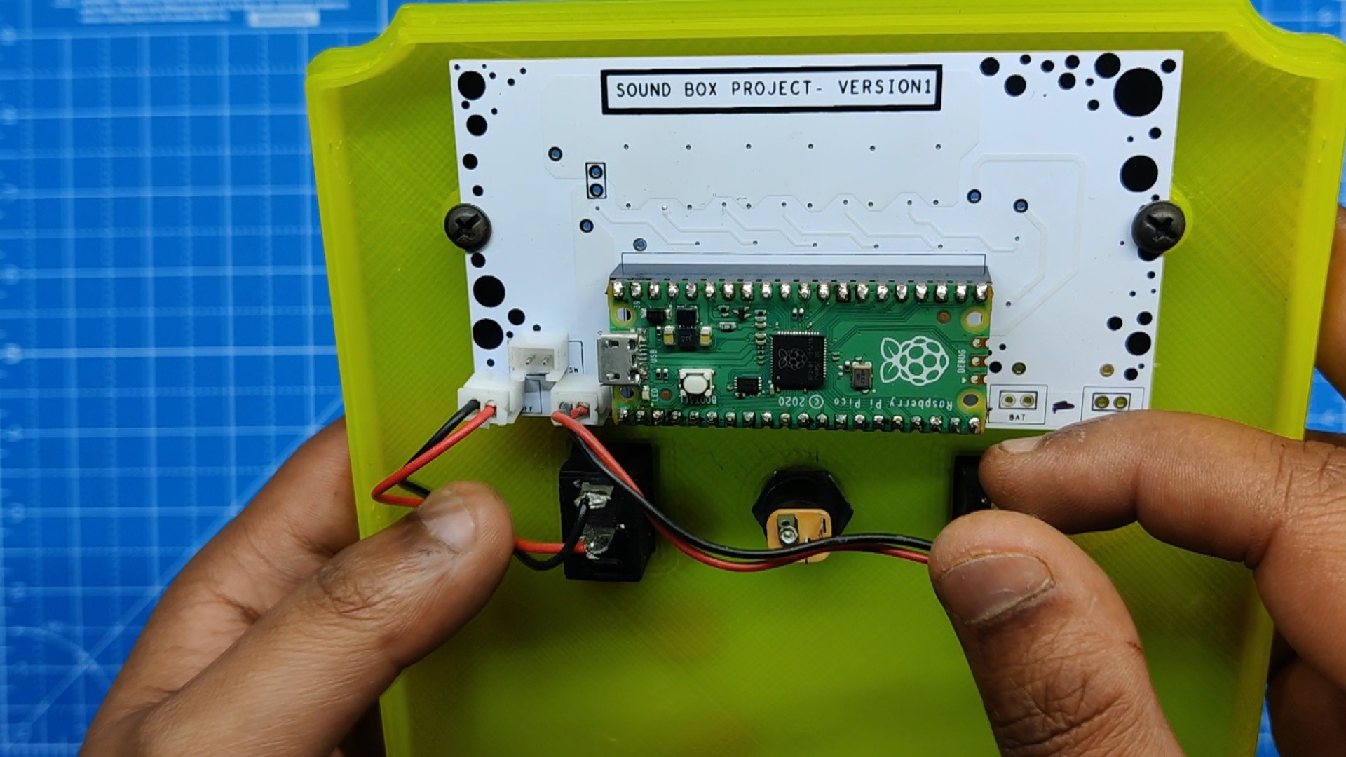
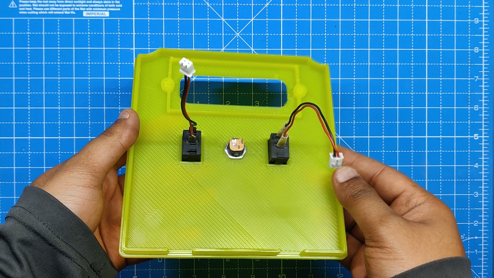
- The JST CON2 Wire Harness was attached to the terminals of both Rocker switches, so connecting them to the RGB LED Board is as simple as putting in the wire harness connector on the PCB connector.
- We place both rocker switch in their place, along with the DC Barrel jack.
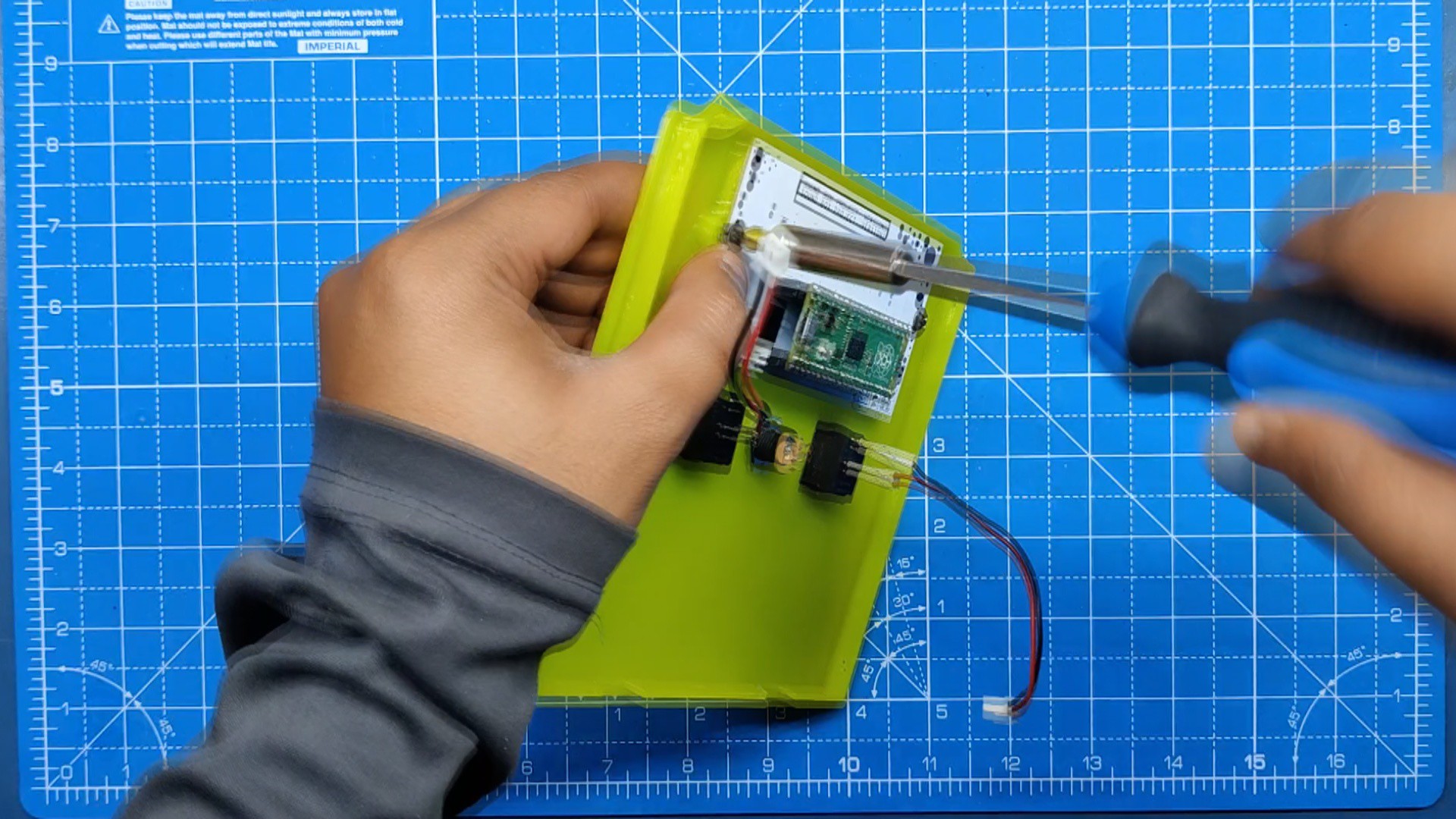
- Subsequently, we set the RGB LED board in its designated spot after adding the diffuser, keeping the diffuser between the PCB and lid.
- PCB is then secured using two M2 Screws.
- Next, we add both rocker switch wire harness on the CON2 of the RGB LED PCB.
-
7Power Source
![]()
![]()
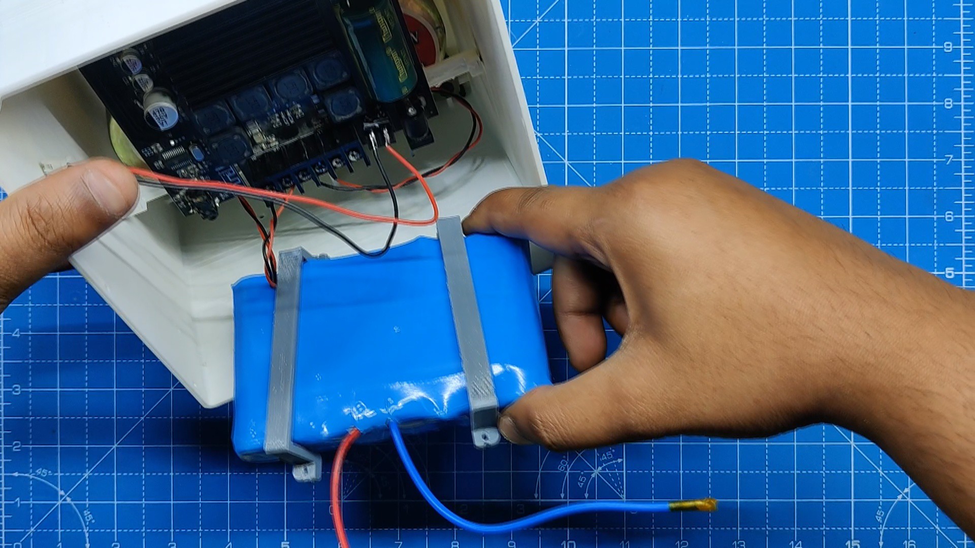
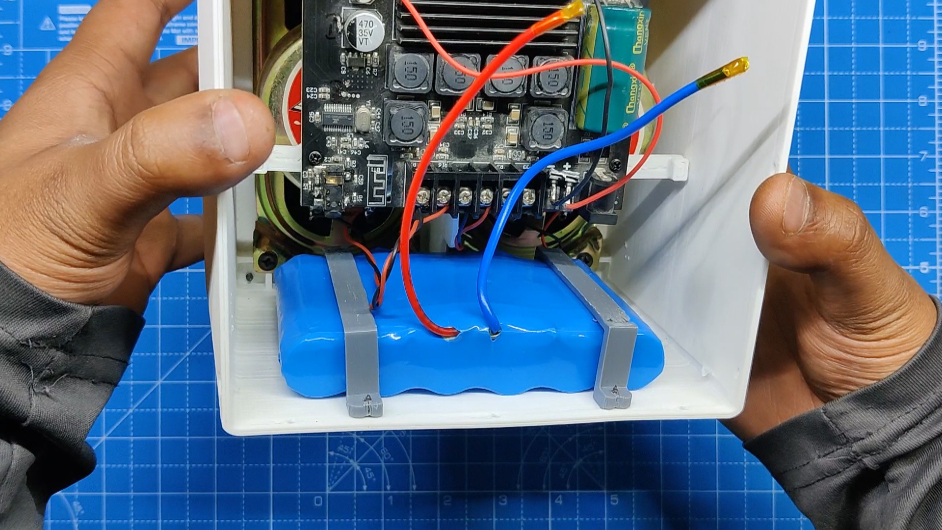
As for the battery source, we are using a 12V 5.2Ah Li-ion Battery Pack which contains an internal BMS, which means this pack offer over charge and over discharge cutoff feature.
We constructed two battery pack clamps to attach the battery pack within the base. Four M2 screws are used to fasten the clamps to the base body, holding the battery pack in place.
-
8Final Assembly
![]()
![]()
![]()
![]()
- The last step in assembly is to connect the power wire harness of the Audio Module to the RGB LED Board's audio connector.
- next, we solder the battery terminals to the RGB LED Board's battery terminals and the wiring process is completed.
- After sliding the lid into position on the back, we fasten the main body to the back lid using six M2 screws.
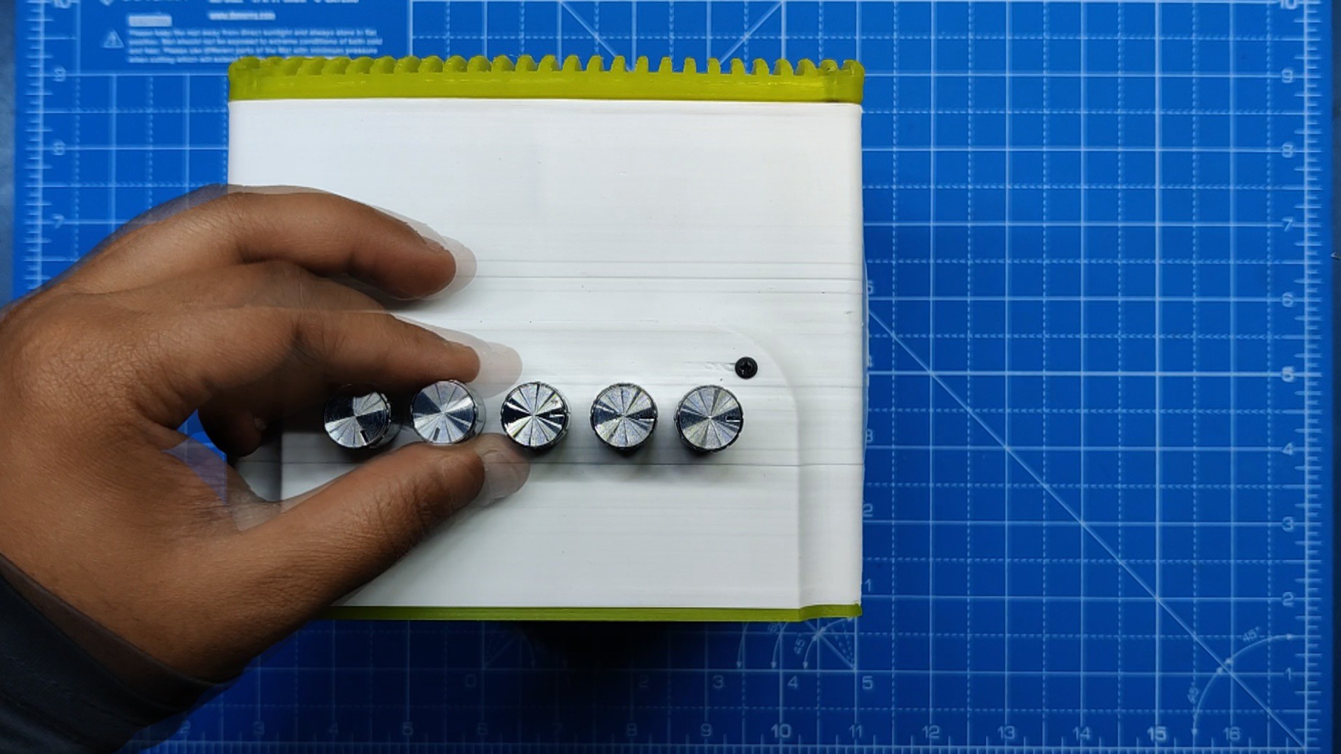
- Lastly, we install the potentiometer knobs that came with the Audio Module kit on them.
THE ASSEMBLY PROCESS IS NOW COMPLETED!
-
9Result
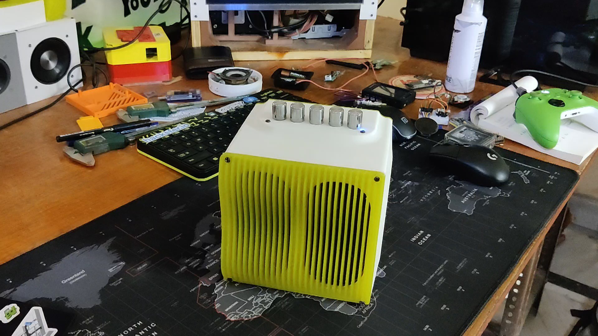
Here's the END RESULT of this simple build, a Loud Boxy Sound System which looks like a cube.
We tested the audio quality by pairing an IPAD with this Sound BOX via Bluetooth and playing a few songs. You can listen to the music for yourself by watching the video below.
An intriguing addition to this speaker was the RGB LED that illuminates the background and plays the Pacifica animation continuously.
Overall this project was a complete success and require no further versions.
I have included all the files, so you may try making one on your own.
Leave a comment if you need any help regarding this project. This is it for today, folks.
Thanks to PCBWAY for supporting this project.
You guys can check them out if you need great PCB and stencil service for less cost and great quality.
And I'll be back with a new project pretty soon!
SoundBox
SoundBox is a 3D Printed Portable Bluetooth Speaker system, It also contains an RGB Board powered by Pico for aesthetics.
 Arnov Sharma
Discussions
Become a Hackaday.io Member
Create an account to leave a comment. Already have an account? Log In.