Close
0%
0%

SoundBox

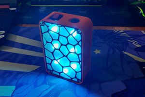
SoundBox is a 3D Printed Portable Bluetooth Speaker system, It also contains an RGB Board powered by Pico for aesthetics.

Public Chat
Similar projects worth following
Hi everyone, happy to be back!

Enjoy something loud! The Sound Box Project is a Bluetooth speaker made completely from scratch using a custom PCB and 3D printed parts.
The goal was to put together a powerful Bluetooth sound system for my desk to replace the sound speaker project I had previously made.

https://www.hackster.io/Arnov_Sharma_makes/3d-printed-boombox-b3bbb1

Here, we are using a 12V 5.2A battery source in conjunction with two powerful 15W speakers and a ZK-TB21 audio module.

In addition, we have incorporated a custom RGB led driver that powers the background illumination on the back side of the sound system using a Raspberry Pi Pico for aesthetic purposes.

The Soundbox has five sound control knobs which control frequency, tremble, volume and bass.

VIDEO-

DESIGN

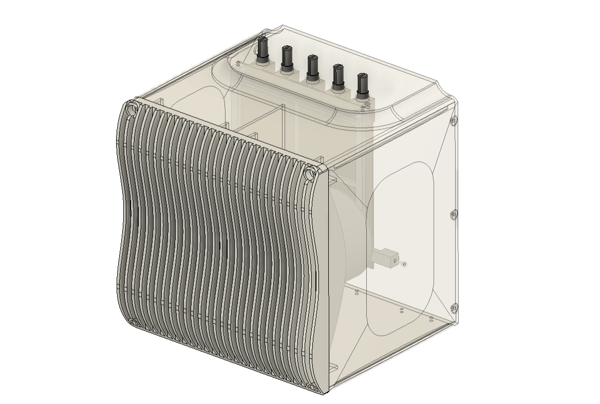
Here is the simple design I came up with. The entire body is designed in the shape of a cube, and the front has a speaker grill created of splines.

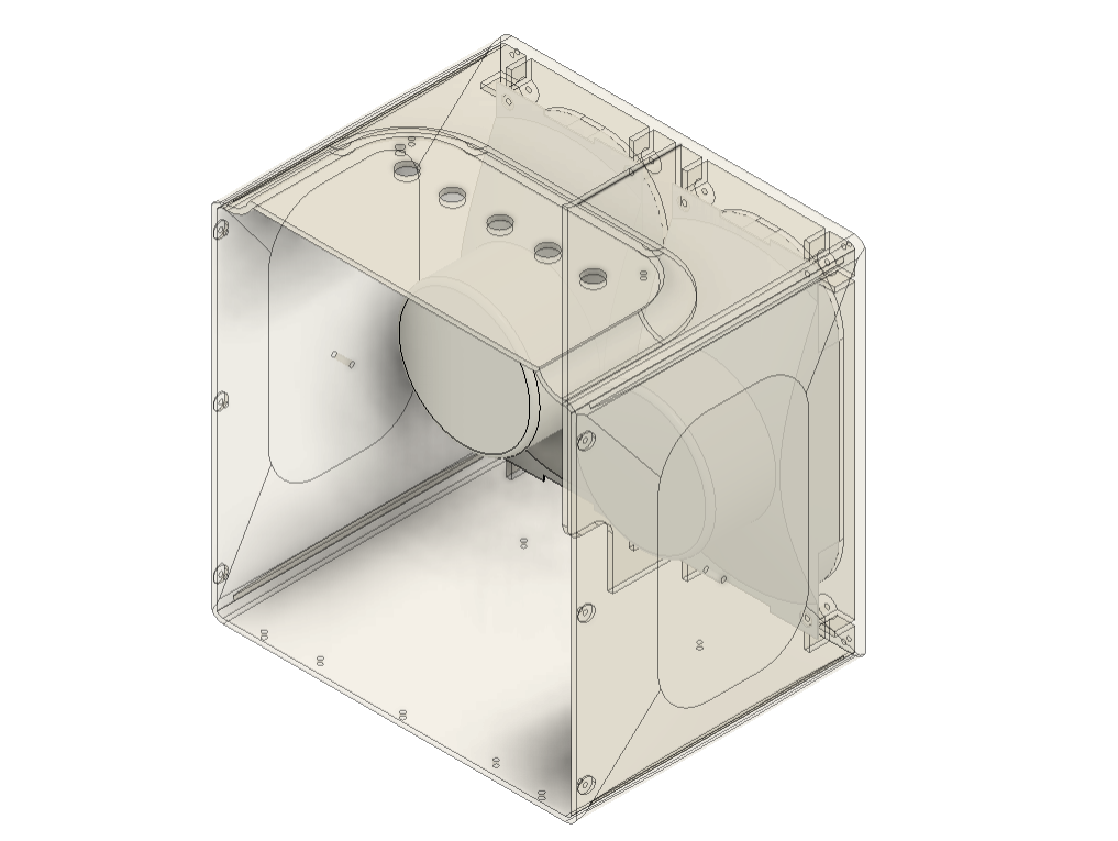
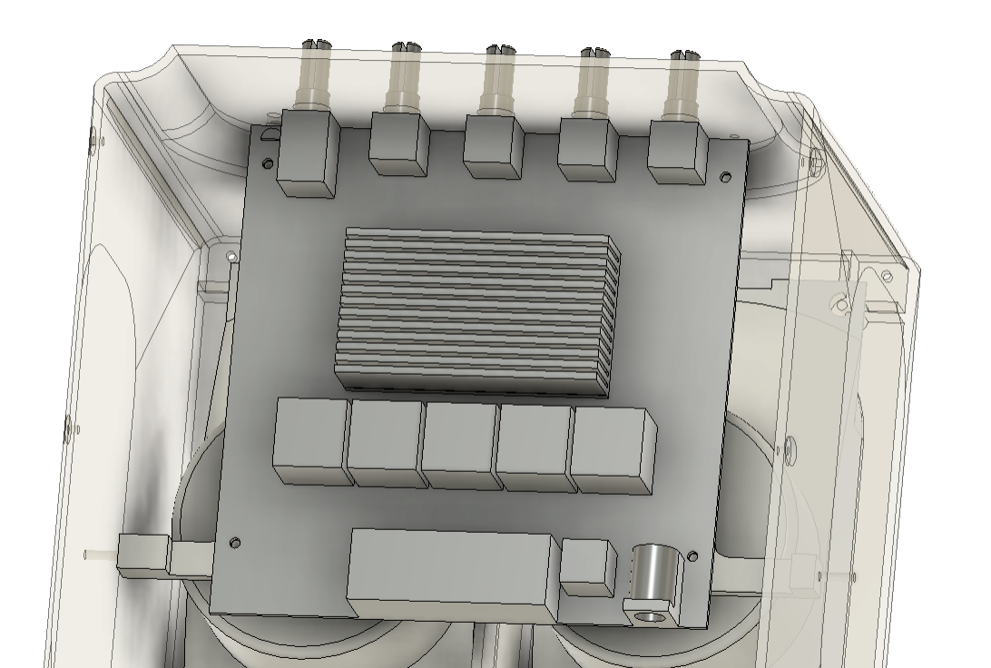
Control knobs for the Audio Module were positioned on the top face, and an RGB LED diffuser that lights up the background is located on the rear side of the speaker.

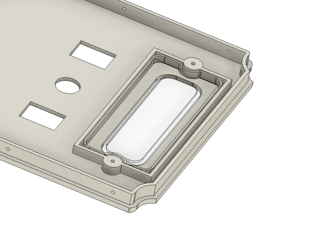
Additionally, there are two rocker switches on the bottom side that control the power supply for the speakers and the RGB light. A DC Jack is located on the back of the device to charge the battery.

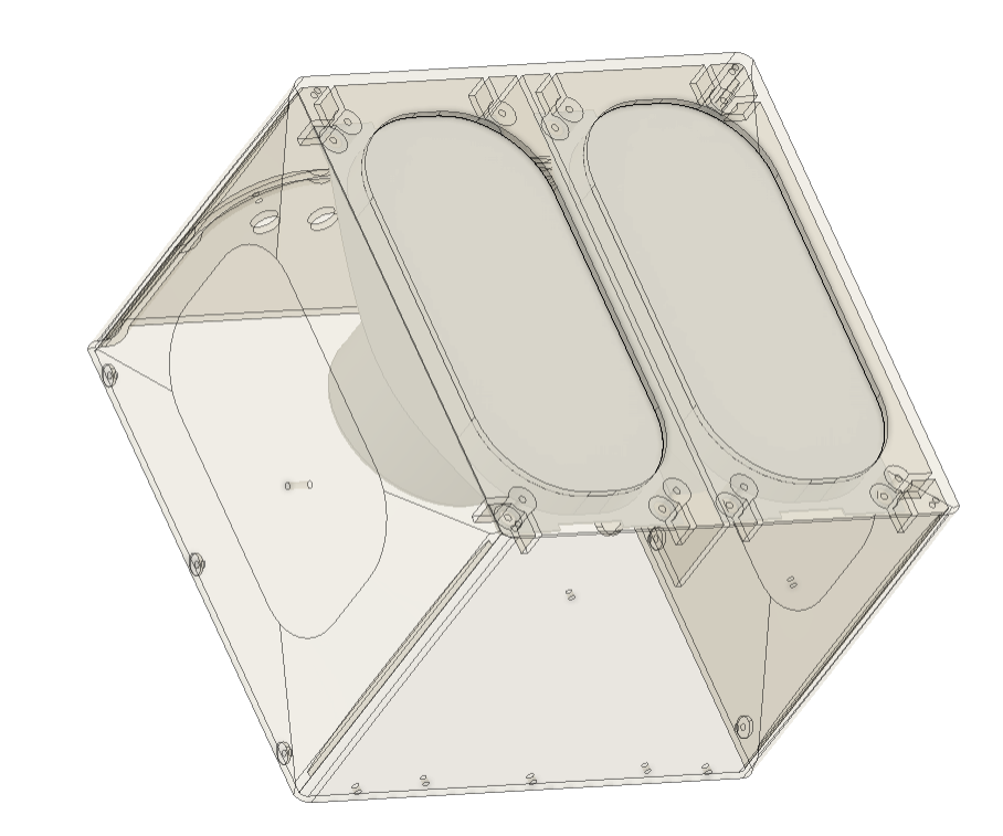
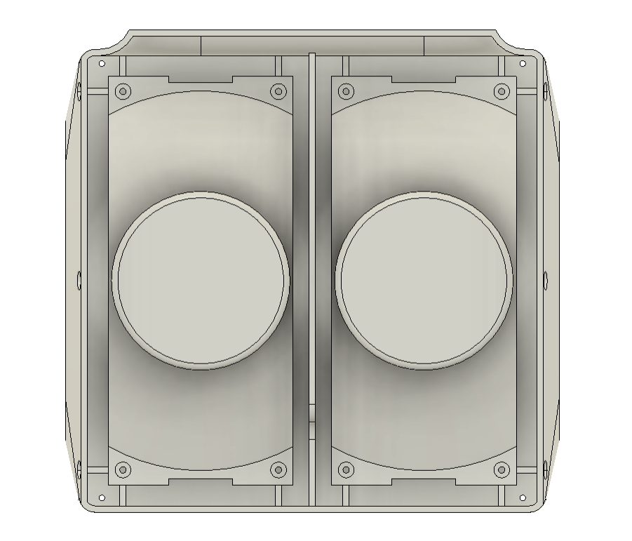
Regarding the internals, we put the two speakers we used on the interior of the front face of the project.

The speaker grill was modeled to fit on the front face using four M3 screws situated at each corner.

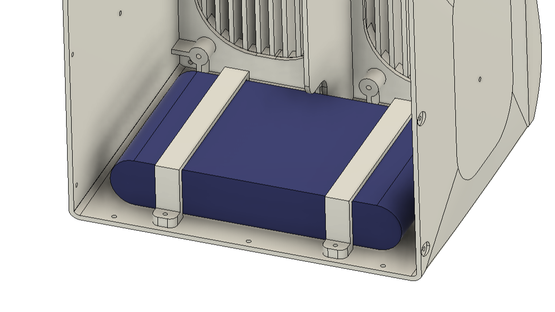
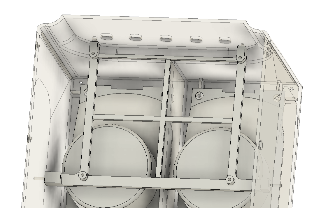
We have created a holder element that is first secured to the mounting holes on the audio module, and then the entire assembly is fixed within the base to keep it in place.

After exporting each component into an STL file, they were all 3D printed using white PLA and golden yellow PLA with a 0.2mm layer height and a 1mm nozzle.

PCB Design


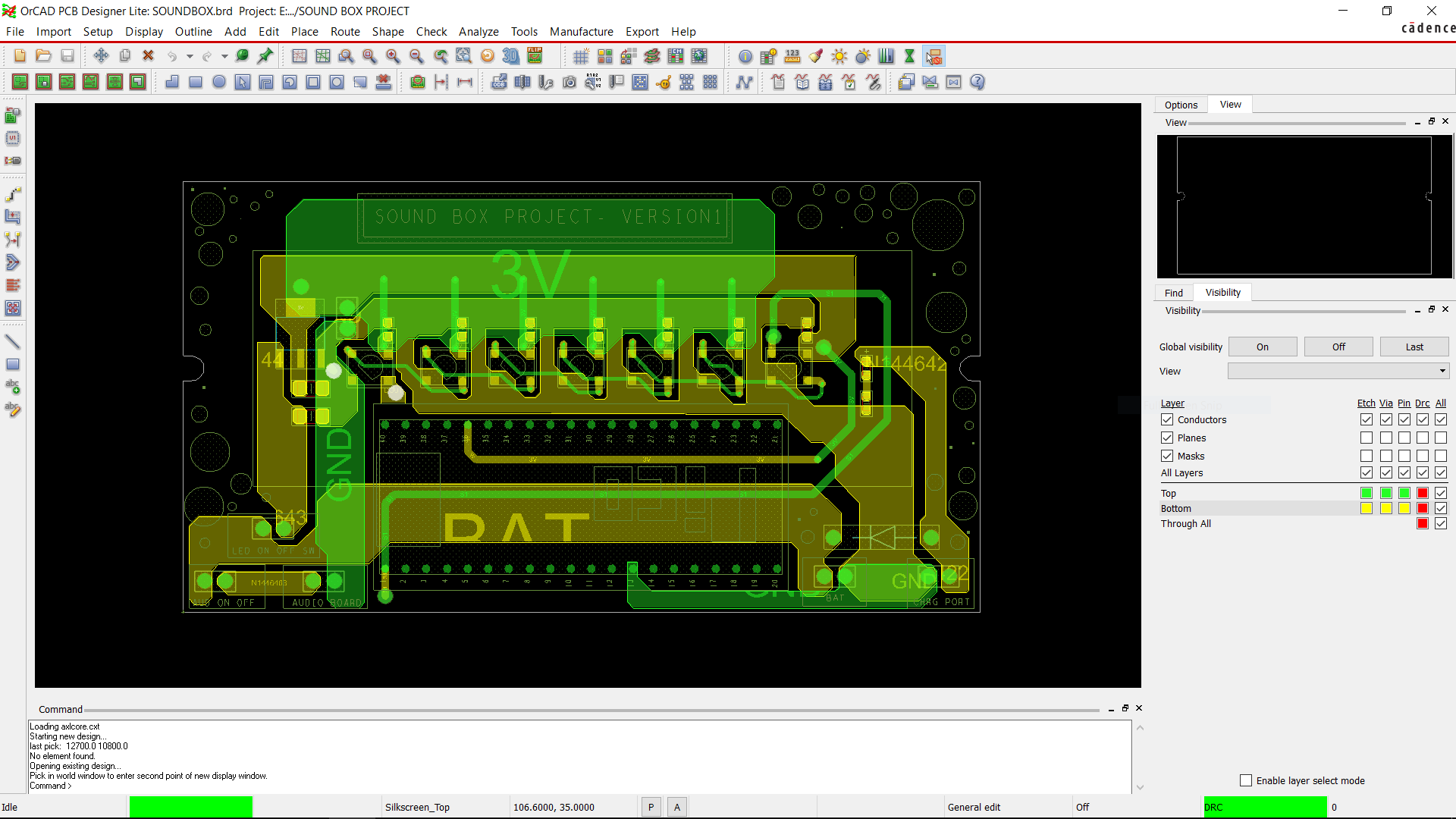
The PCB Design of this project's RGB Board was super simple as it only contains an array of WS2812B RGB LEDs connected in parallel with an Raspberry Pi Pico.

Schematic was made in total three sections which were the AMS1117 and battery section, the Raspberry Pi Pico Setup and the WS2812B LEDs array.

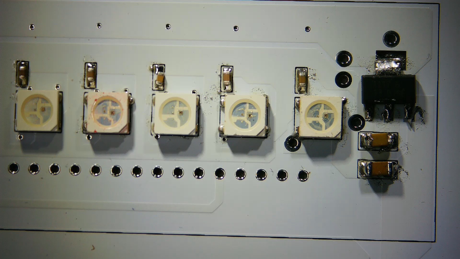
We needed to add an AMS1117 Voltage regulator configuration in order for the Raspberry Pi Pico and LEDs to function because we were utilizing a 12V Li-ion battery as our power source. This arrangement steps down the 12V of the battery to a steady 3.3V.

Two capacitors are connected to the input and output terminals of the AMS1117 in the simplest configuration. A 10uF 1206 capacitor is attached to the input side, while a 1uF 1206 capacitor is linked to the output side. Additionally, an M7 Diode and a switch have been placed between the input con2 terminal and the ams1117. A DC jack will be added using the CON2 to charge the 12V battery.

Each RGB LED was connected to a 100 nF capacitor for decoupling of the supply line.

Following the creation of the schematic, we create the PCB design and layout the components on the board, based on the PCB model created in Fusion 360.

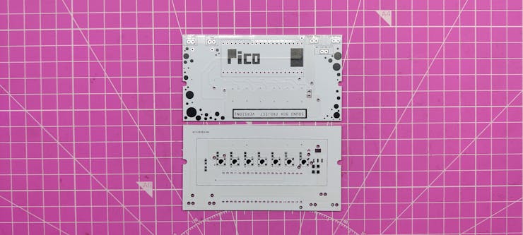
All of the SMD components, RGB LEDs, and the AMS1117 setup were mounted on the bottom. On the top side of the PCB were Pico and additional THT components.

PCBWAY Service
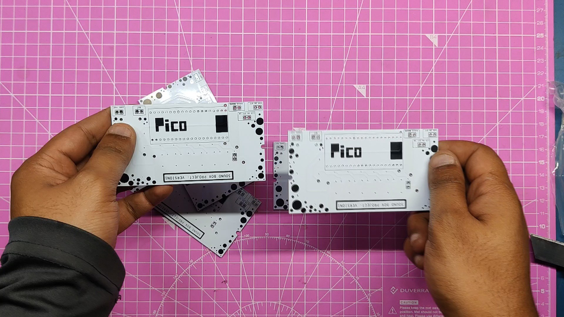

PCBWAY provided the PCBs for this project; we uploaded the Gerber data to their PCB Quote page and placed an order for white solder masks with black silkscreen.

We received the PCBs in less than a week, which was extremely fast, and the quality was excellent as usual.

I've been using their service for a while now, and it's always excellent.

https://www.pcbway.com/

Check out PCBWAY for great PCB service at a low cost.

GRILL.stl

Standard Tesselated Geometry - 654.67 kB - 04/30/2024 at 15:49

Download

SOUND BOX PROJECT v12.step

step - 3.23 MB - 04/30/2024 at 15:49

Download

SOUND BOX PROJECT v12.f3d

fusion - 5.18 MB - 04/30/2024 at 15:49

Download

SOUND BOX.step

step - 3.21 MB - 04/30/2024 at 15:49

Download

body.stl

Standard Tesselated Geometry - 1.33 MB - 04/30/2024 at 15:49

Download

View all 11 files

  • 1
    PCB ASSEMBLY
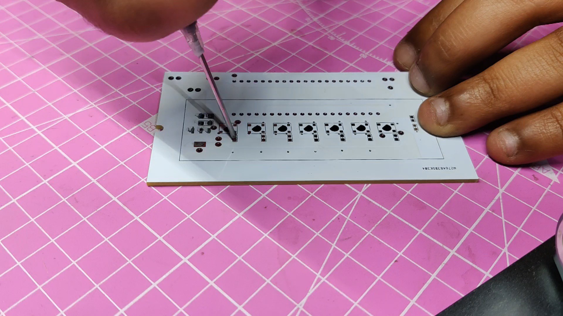
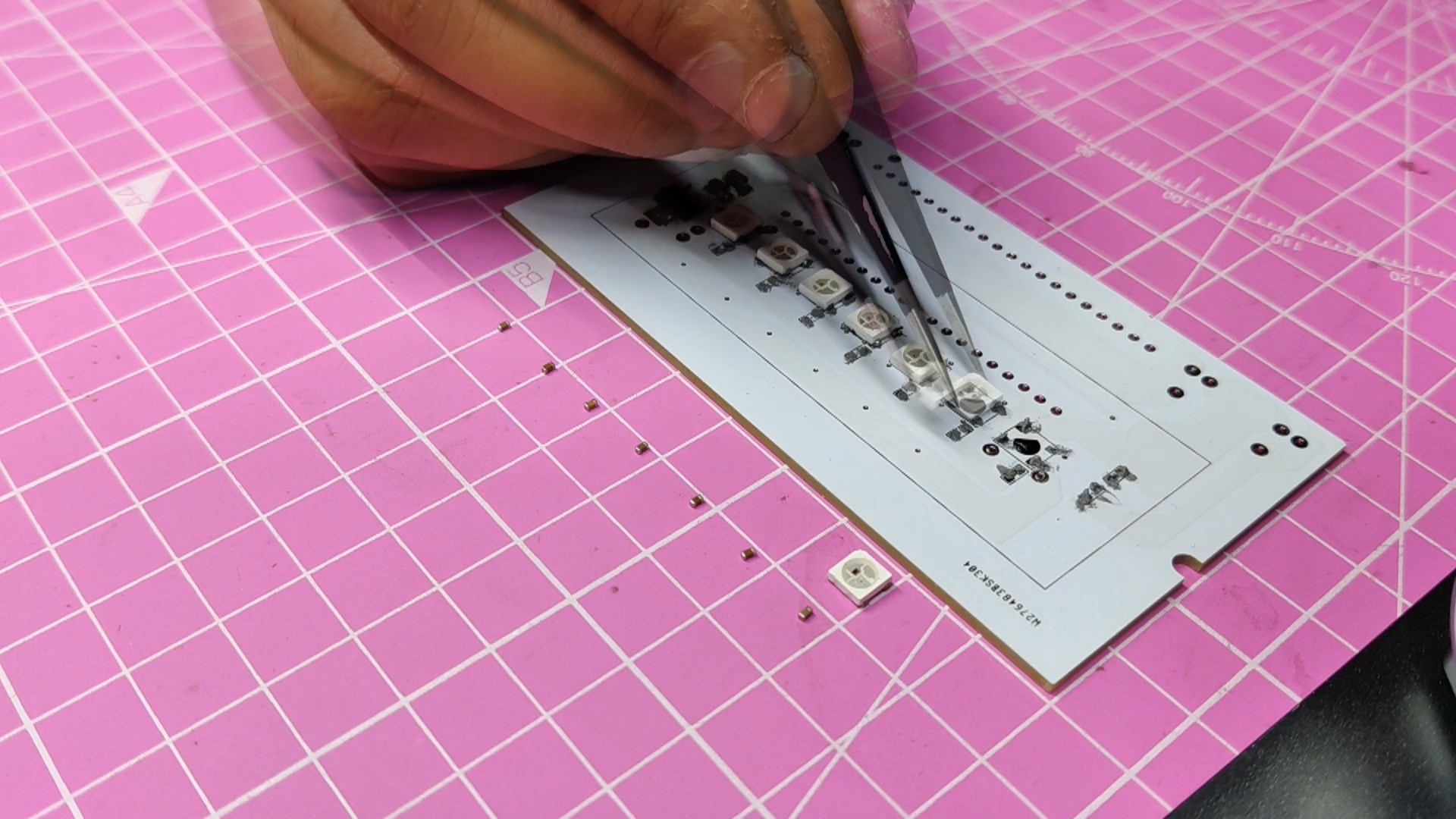
    • Using a solder paste dispensing needle, we first add solder paste to each component pad individually to begin the PCB assembly process. In this instance, we are using standard 37/63 solder paste.
    • Next, we pick and place all the SMD components in their places on the PCB using an ESD tweezer.
    • With extreme caution, we lifted the complete circuit board and placed it on the SMT hotplate, which increases the PCB's temperature to the point at which the solder paste melts and all of the components are connected to their pads.
    • Next, we add all the THT components, which include the header pin, Raspberry Pi Pico, and CON2 JST Connectors, to their locations and then solder their pads using a soldering iron.

    THE PCB IS NOW READY!

  • 2
    Audio Module and Sound Hardware

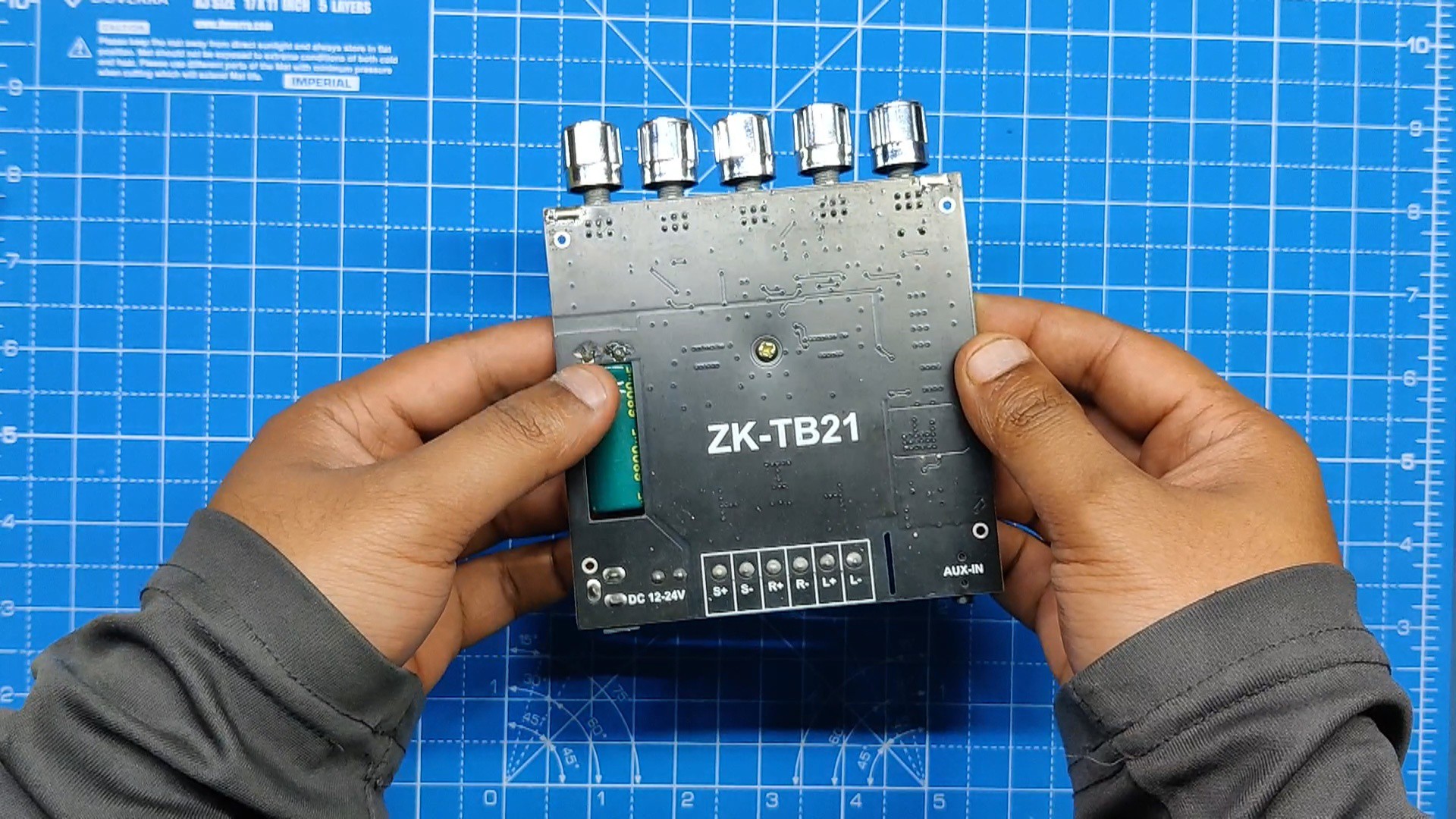
    The ZK-TB21 is being used in this project, which is a 2.1-channel audio power amplifier based around the TPA3116D2 power amplifier chip.

    TPA3116D2 is a Class D stereo amplifier that can drive speakers up to 100 watts. To drive two 100-watt speakers, the ZK-TB21 utilizes two of these TPA3116D2 chips. one for the left and right speakers, and one for the subwoofer

    Also, there's a Bluetooth audio IC on this board, which lets us connect with this board for audio streaming.

    Technical Specifications of Module

    • Product name: 2.1-channel Bluetooth audio power amplifier module
    • Product model: ZK-TB21
    • Bluetooth version: 5.0 (unobstructed, 10 meters)
    • Input sensitivity: 500 mV
    • Input method: AUX + Bluetooth
    • Number of channels: 2.1 channels
    • Power amplifier chip: TPA3116D2 (with AM interference suppression function)
    • Adaptable power supply: DC12~24V / 5A or more (over-voltage, output power setting)
    • Adapt to speakers: 20~100 W, 4~8.
    • Output power: 50W for left and right channels
    • Subwoofer 100W
    • Protection mechanisms: overvoltage, under voltage, overvoltage, DC detection, short circuit protection
    • Product size: 120mm * 100mm * 20mm
    • Product weight: about 256g (including packaging)

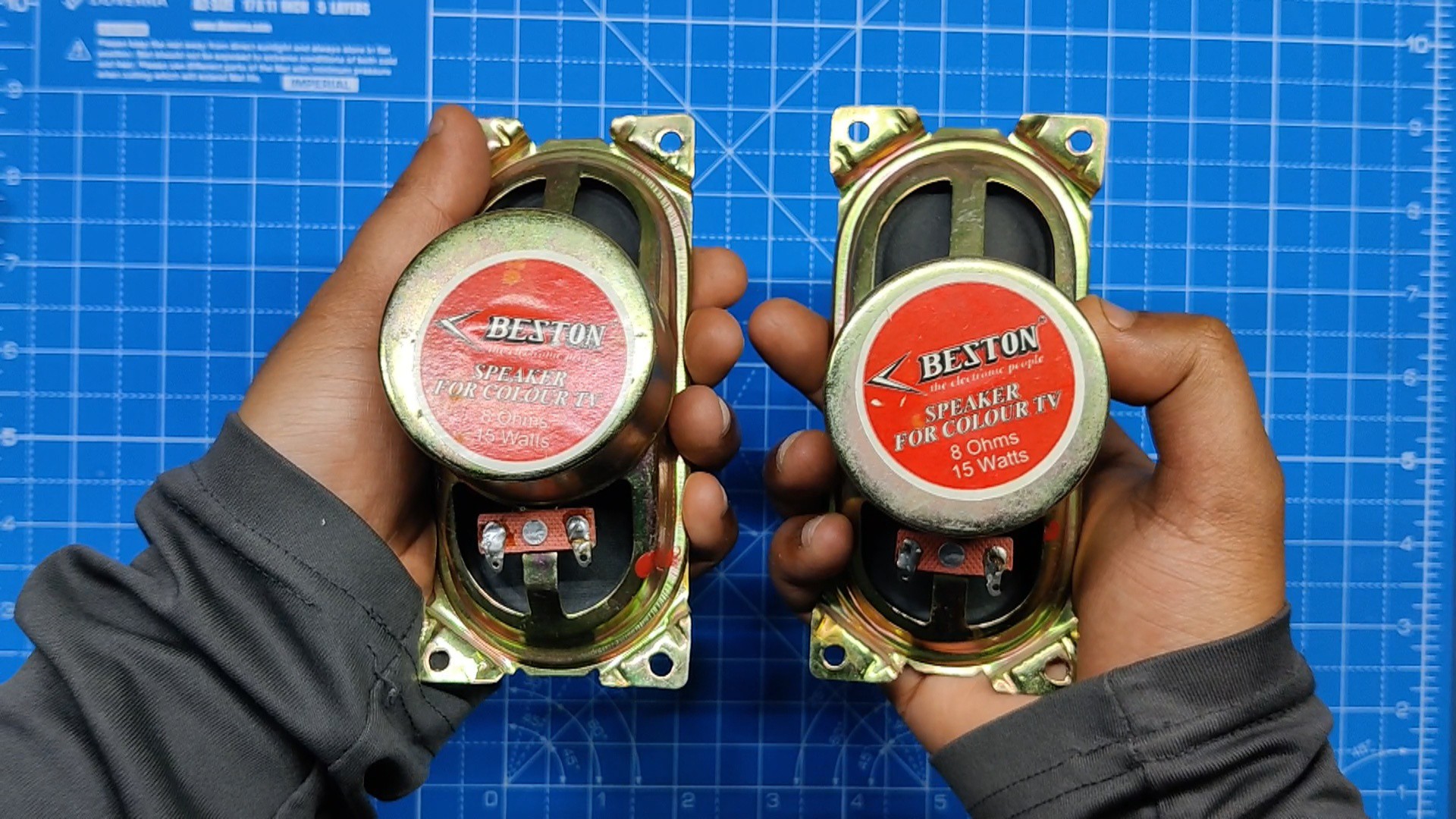
    As for sound, we are using two 8-Ohm, 15-W speakers paired with the ZK-TB21 Audio Module.

  • 3
    Speaker Assembly

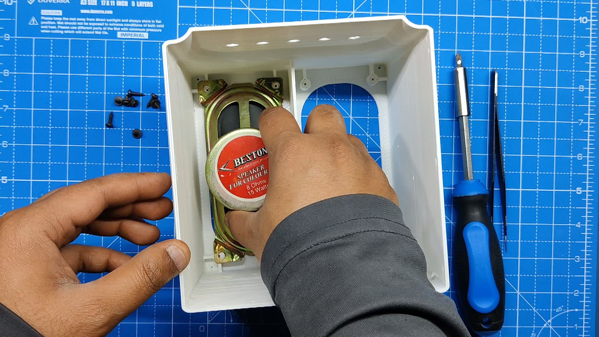
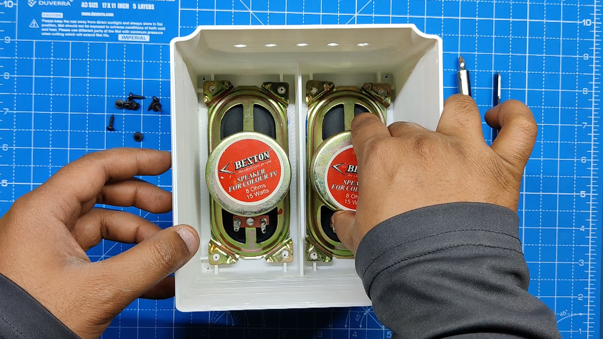
    First, we assemble the speakers, which was quite easy.

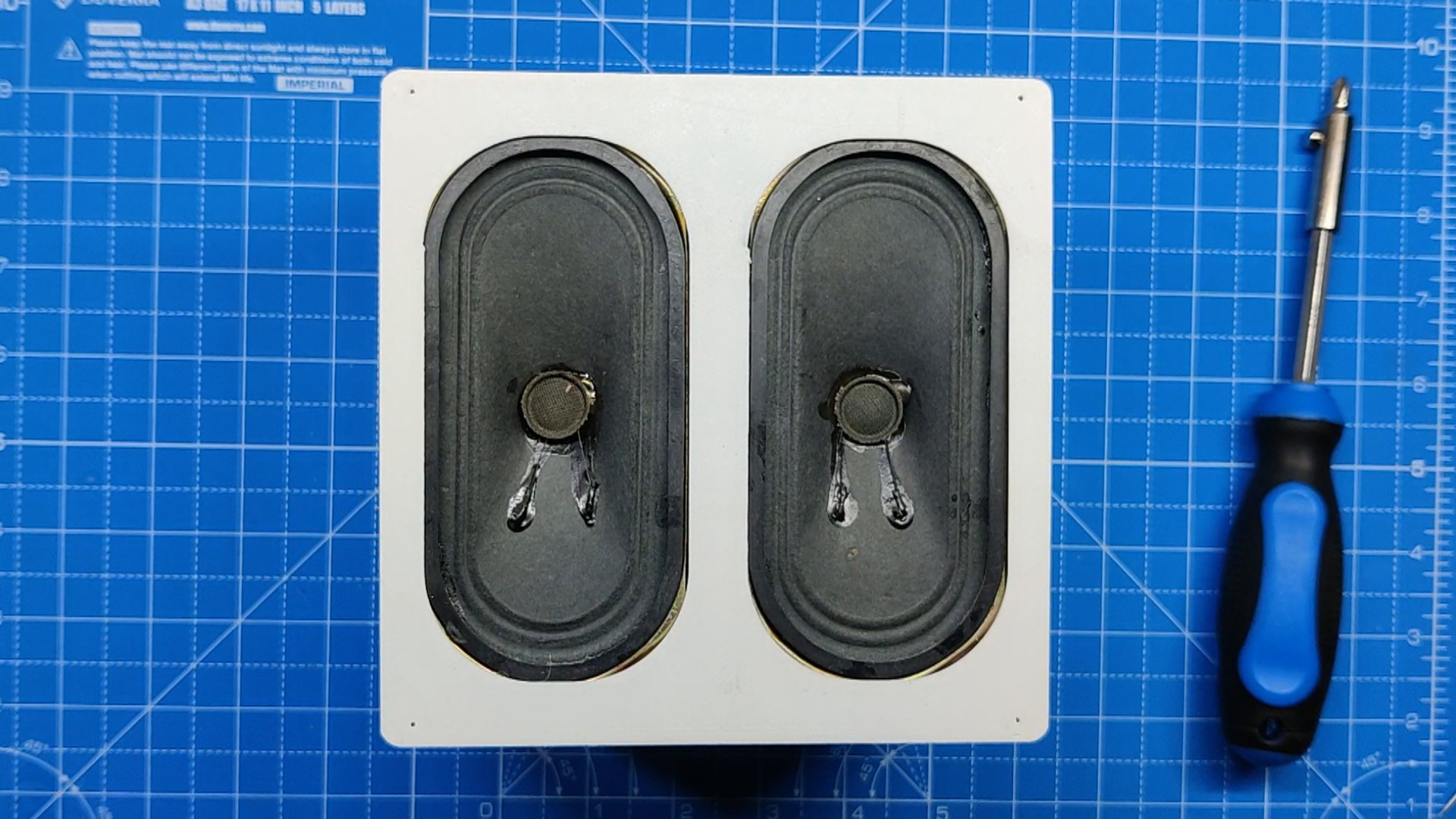
    We take the two 15W speakers and install them inside the Main Base.

    Eight M2 screws were used to permanently fix the speakers after they were positioned inside the main base in their designated spots.

View all 9 instructions

Enjoy this project?

Share

Discussions

Similar Projects

Does this project spark your interest?

Become a member to follow this project and never miss any updates