Close
0%
0%

Game Boy Zero Link

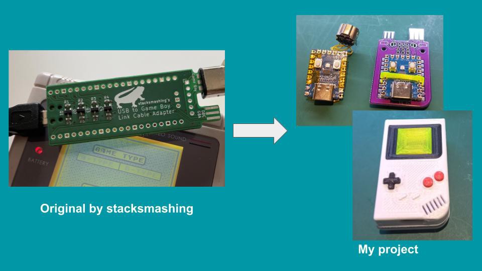
This is a re-implementation of Game Boy Link Cable USB Adapter originally by stacksmashing

Public Chat
Similar projects worth following
This project is an re-implementation of on stacksmashing's Gameboy Link adapter: https://www.youtube.com/watch?v=KtHu693wE9o

The project is split in to three parts:
https://github.com/weimanc/game-boy-zero-link-board
https://github.com/weimanc/game-boy-zero-link-firmware
https://github.com/weimanc/game-boy-zero-link-case

Stacksmashings's Discord server:
https://discord.gg/YASkVQY5Pr

What is it?

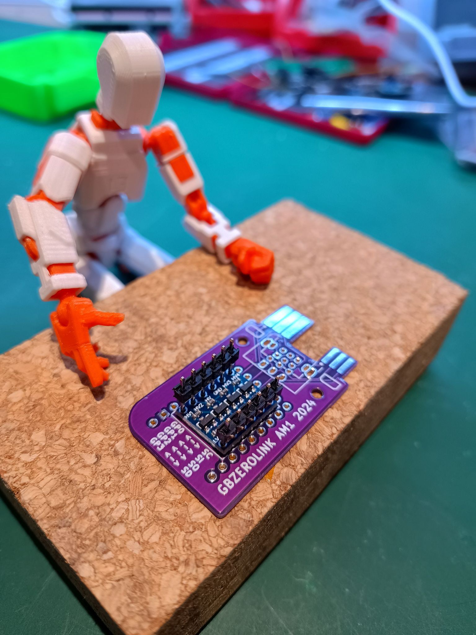
In a nutshell: I've made my own version of @stacksmashing's Game Boy Link Cable, or should I say in a GameBoy shell.
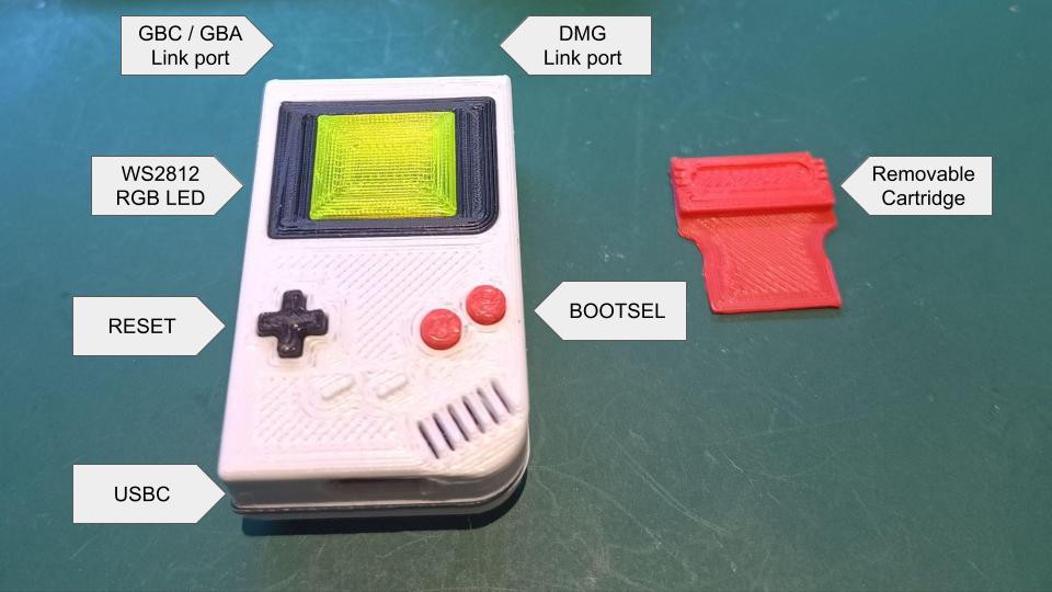
Features

  • USBC port - to connect to a PC or Phone.
  • GBC / GBA / DMG Link port - auto select voltage for the level shifter 3.3V / 5V.
  • Functional Dpad and AB Buttons - RESET and BOOTSEL respectively.
  • RGB LED - visible through the translucent "LCD" screen, color change possible via BOOTSEL button.
  • Removable Cartridge - a Game Boy isn't complete without game cartridges :)
Read more »

  • 1
    PCBA - prep

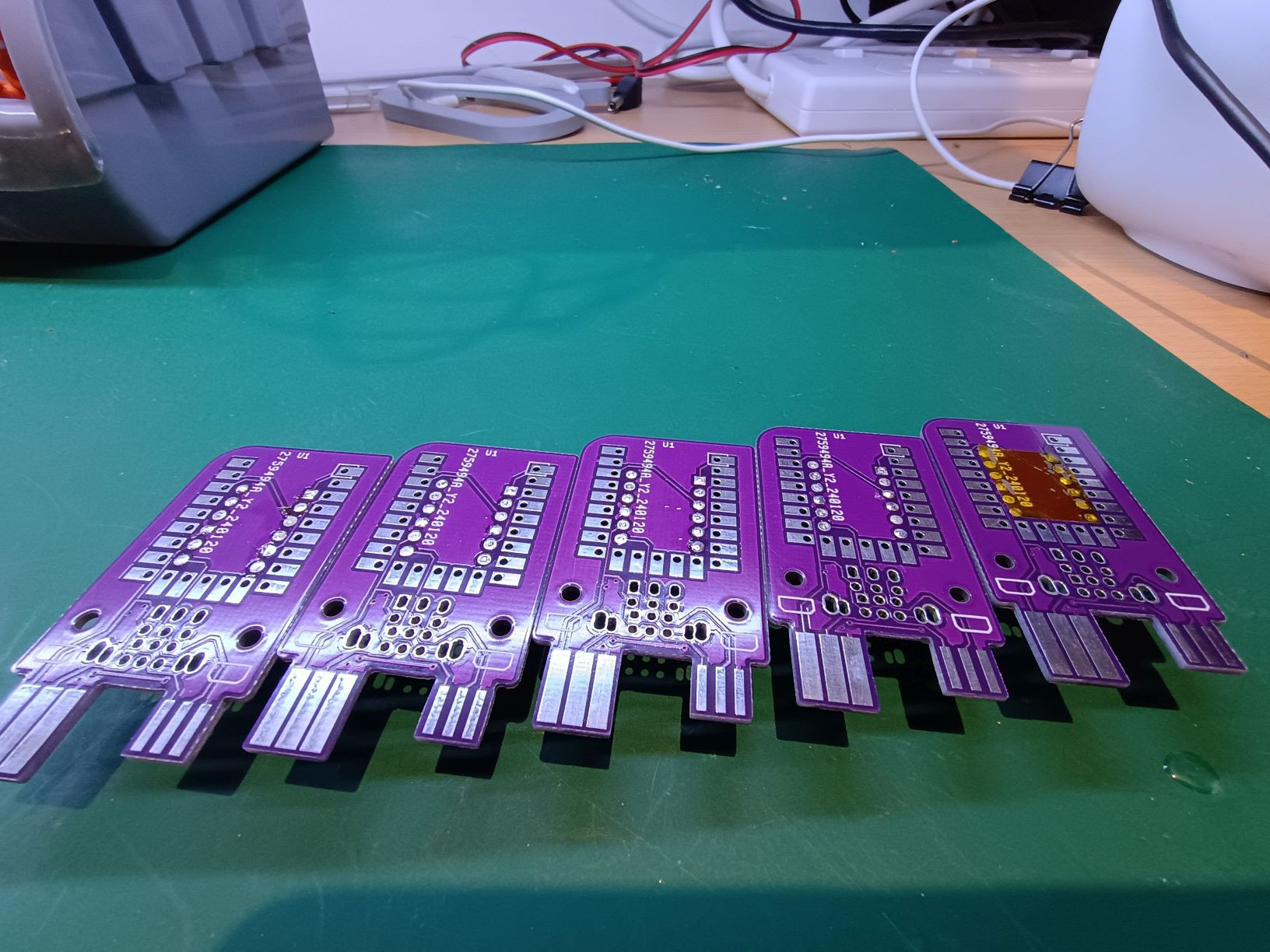
    The PCB has two edge connectors that fits the DMG- or GBC/GBA-link cable. I found that the edge connectors on my PCB's are a bit to wide for my link cable and required some filing. Please test fit the PCB and your link cable before doing any assembly, file down the edges if needed.

  • 2
    PCBA - Level Shifter assembly

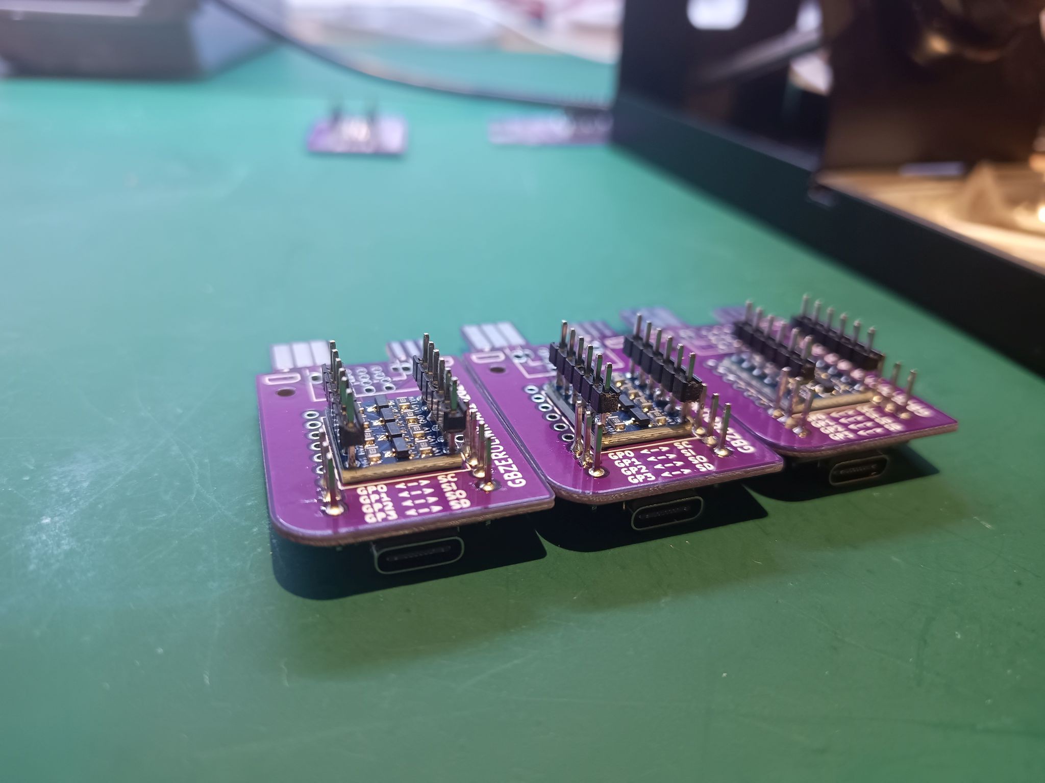
    So save some space, non-standard soldering is required to keep the whole electronics assembly as slim as possible. The Level Shifter PCB will sit directly on top of the game-boy-zero-link-board PCB and insert two 1x6 headers long side first. Make sure you work on a flat surface as you don't want the pin header to protrude on the other side. Please take extra care on the orientation of the Level Shifter. The HV side is wired to the edge connector the LV side is wired to the RP2040.

    Start at the corner and solder the first pin to the Level Shifter. Then do the opposite corner and solder the other header to the Level Shifter. Take time to inspect the alignment: 
    - Level Shifter orientation with respect to the game-boy-zero-link-board PCB?
    - are the headers straight?
    - are the header pins flush on the bottom side of the game-boy-zero-link-board PCB?

    When everything looks good, solder the rest of the pins to the Level Shifter.

    Now flip the assembly. 

    Find the header pins that aren't protruding and fill in the Level-Shifter-holes with a small amount of solder. Keep this side as flat as possible.

    Finish this step with a piece of kapton tape and cover the soldered holes of the Level Shifter.

  • 3
    PCBA - RP2040-Zero

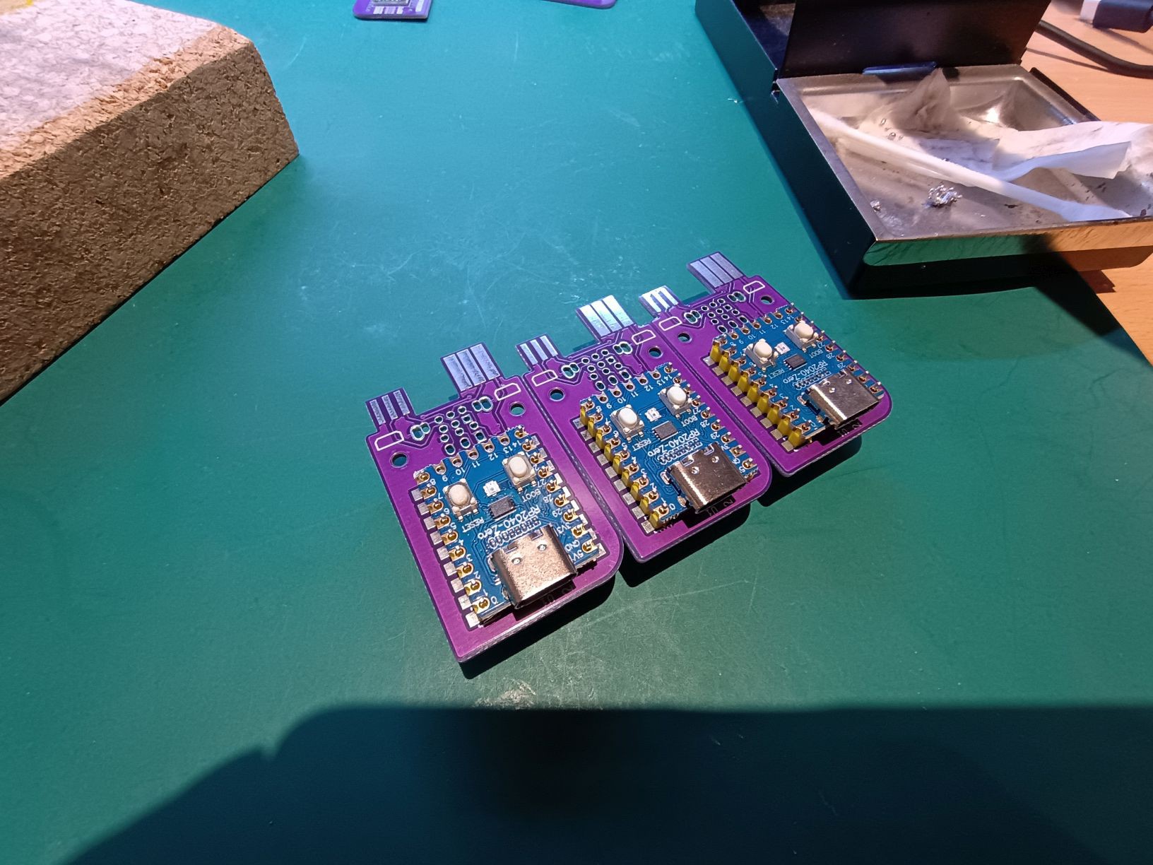
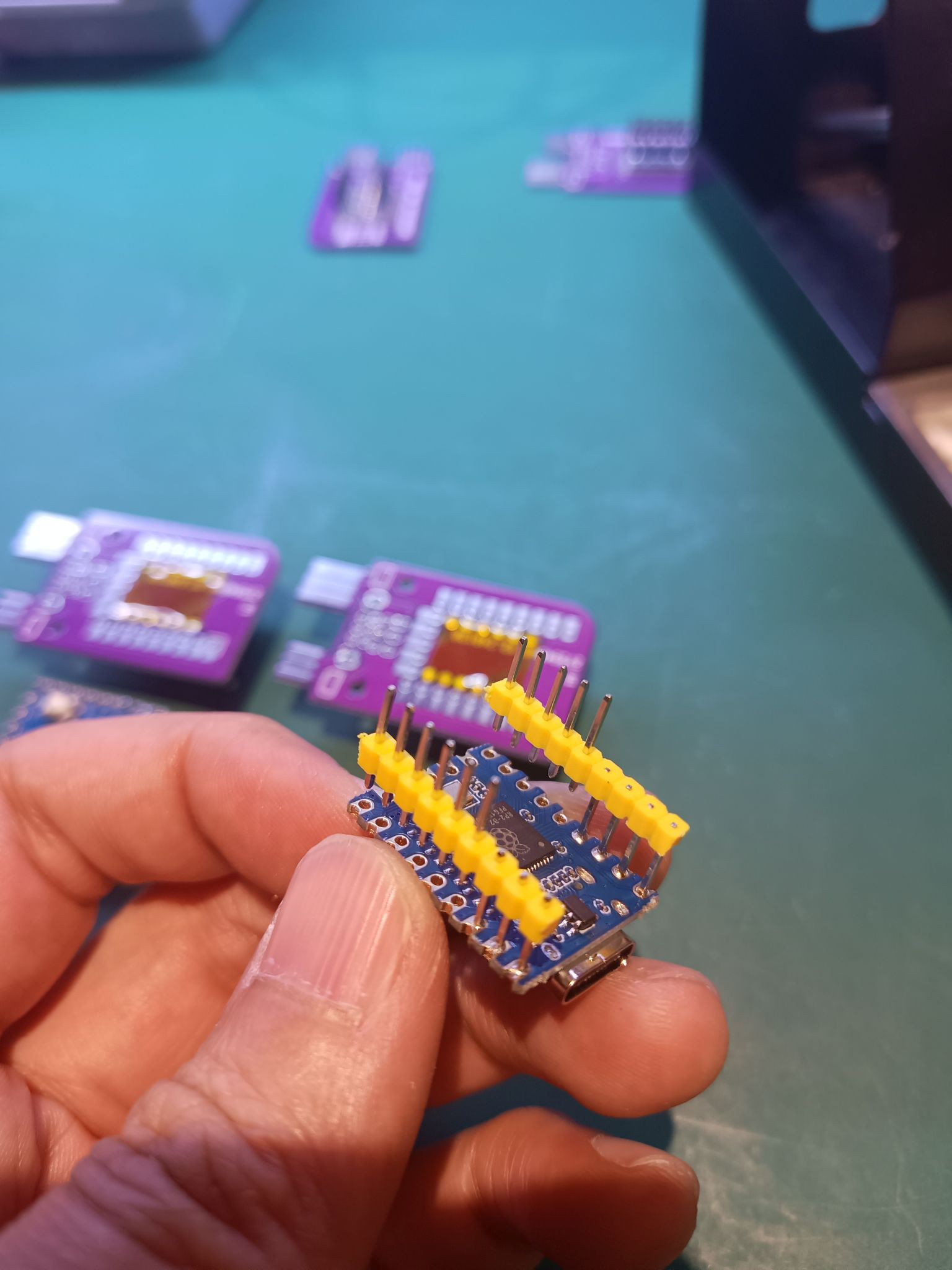
    Again we have to do some non-standard soldering. Insert two rows 1x9 headers, long end first, to the game-boy-zero-link-board PCB.

    Place the RP2040-Zero board on the short end of the headers on top.

    Next we solder the pin header to the RP2040-Zero board. Not all the pins of RP2040-Zero are used. I opted to not solder all the pins.
    - solder the first four pins: PIN1 PIN2 PIN3 PIN4
    - solder the last three pins: PIN21 PIN22 PIN23

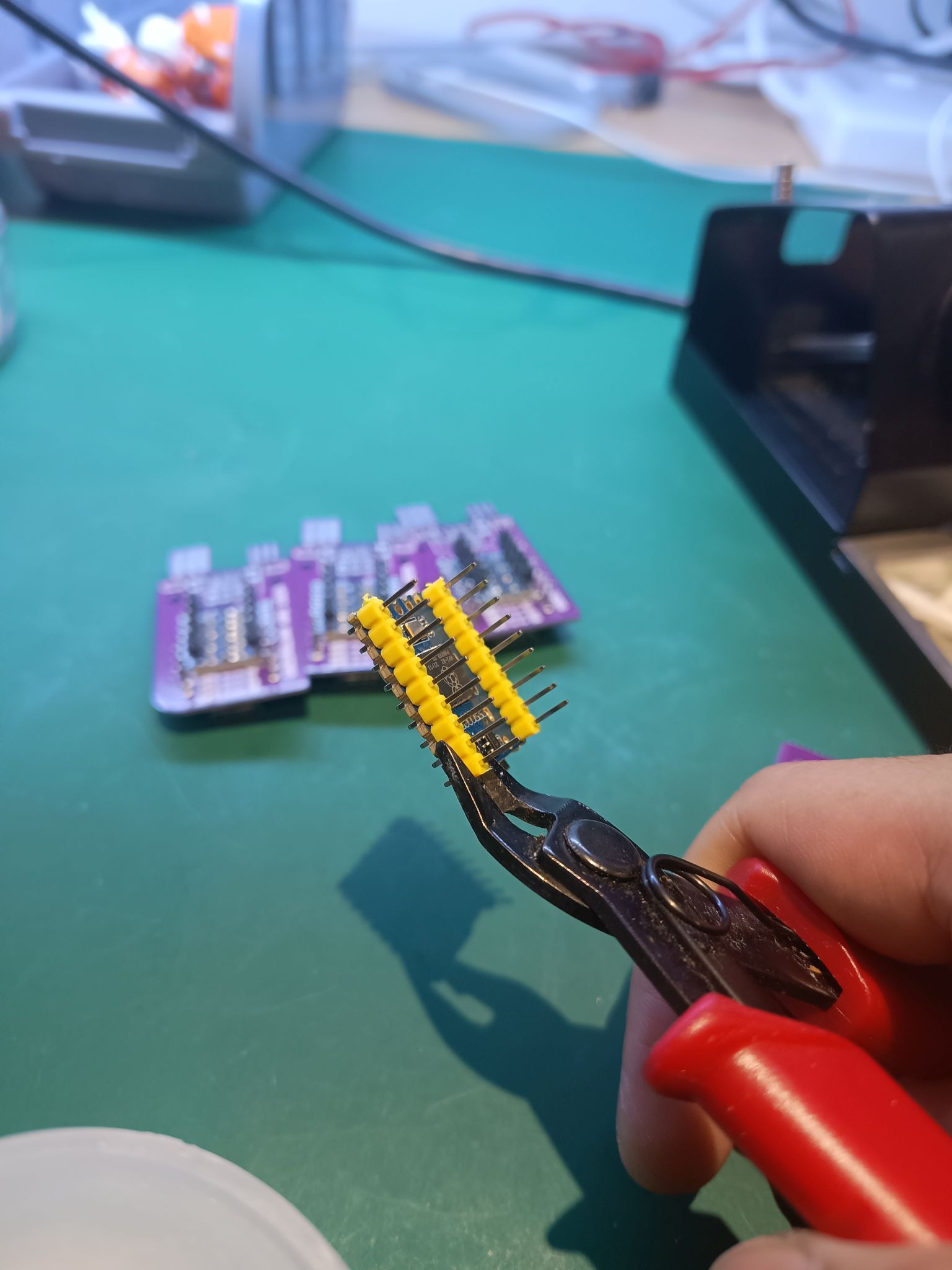
    We want remove the unsoldered pins and remove the plastic shroud. The method that worked for me is to use a wire cutter with a flat side. Work on the pins that you just have soldered in. Have the cutter's flat side close to the PCB and gently apply force. This should force the plastic shroud to move up and way. You should be able to pry off the plastic shroud with the unsoldered pins from the RP2040-Zero.

    With only 7pins left on the RP2040-Zero board, we can start to solder to the game-boy-zero-link-board PCB. 

    Start solder one corner. Try to align the RP2040-Zero board. This can be a bit tricky as the you might find that the RP2040-Zero's tallest component is the SOT23 component underneath the USBC connector. Take your time and try to keep the RP2040-Zero parallel to the game-boy-zero-link-board PCB.

View all 10 instructions

Enjoy this project?

Share

Discussions

Similar Projects

Does this project spark your interest?

Become a member to follow this project and never miss any updates