The PCB has two edge connectors that fits the DMG- or GBC/GBA-link cable. I found that the edge connectors on my PCB's are a bit to wide for my link cable and required some filing. Please test fit the PCB and your link cable before doing any assembly, file down the edges if needed.
2
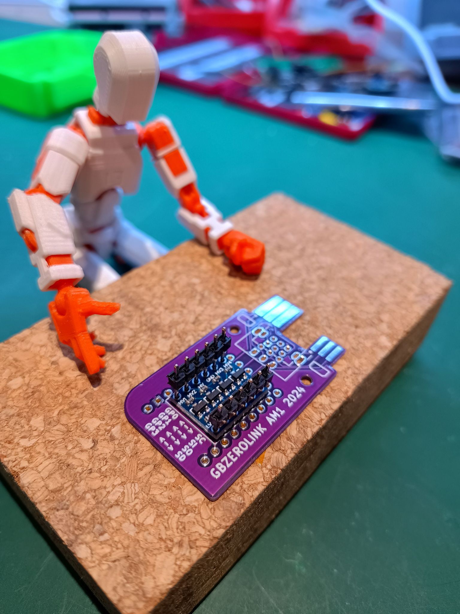
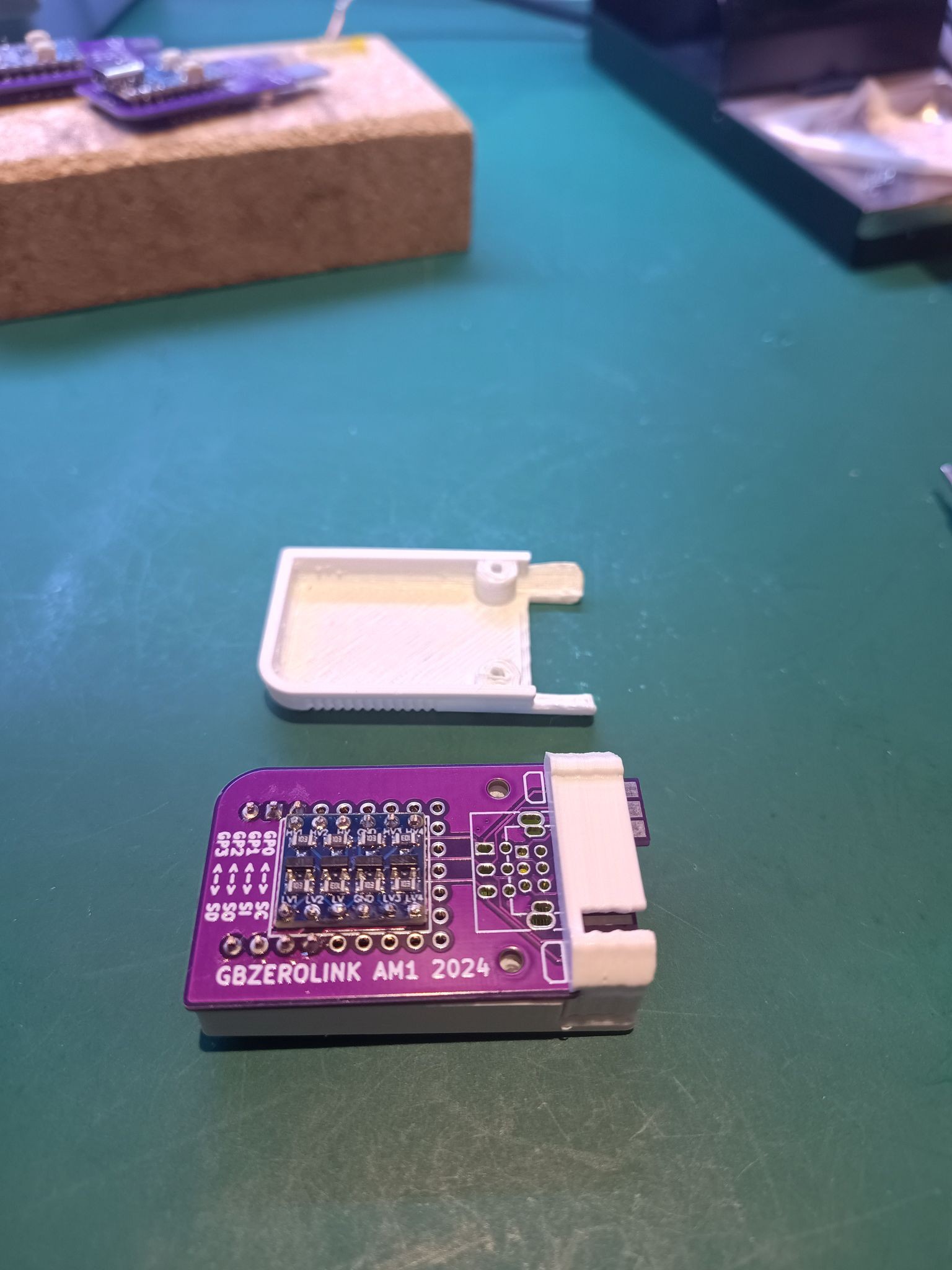
PCBA - Level Shifter assembly
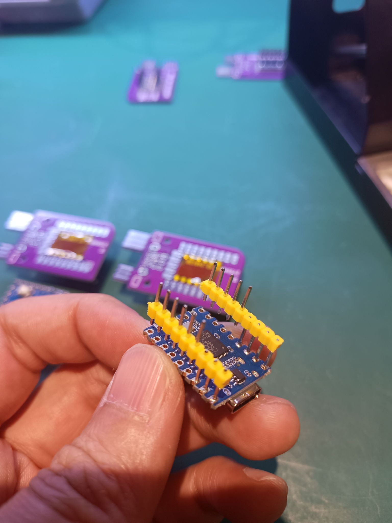
So save some space, non-standard soldering is required to keep the whole electronics assembly as slim as possible. The Level Shifter PCB will sit directly on top of the game-boy-zero-link-board PCB and insert two 1x6 headers long side first. Make sure you work on a flat surface as you don't want the pin header to protrude on the other side. Please take extra care on the orientation of the Level Shifter. The HV side is wired to the edge connector the LV side is wired to the RP2040. In photo below, the HV side is on the left and the LV side is on the right.
Start at the corner and solder the first pin to the Level Shifter. Then do the opposite corner and solder the other header to the Level Shifter. Take time to inspect the alignment: - Level Shifter orientation with respect to the game-boy-zero-link-board PCB? - are the headers straight? - are the header pins flush on the bottom side of the game-boy-zero-link-board PCB?
When everything looks good, solder the rest of the pins to the Level Shifter.
Now flip the assembly.
Find the header pins that aren't protruding and fill in the Level-Shifter-holes with a small amount of solder. Keep this side as flat as possible.
Finish this step with a piece of kapton tape and cover the soldered holes of the Level Shifter.
3
PCBA - RP2040-Zero
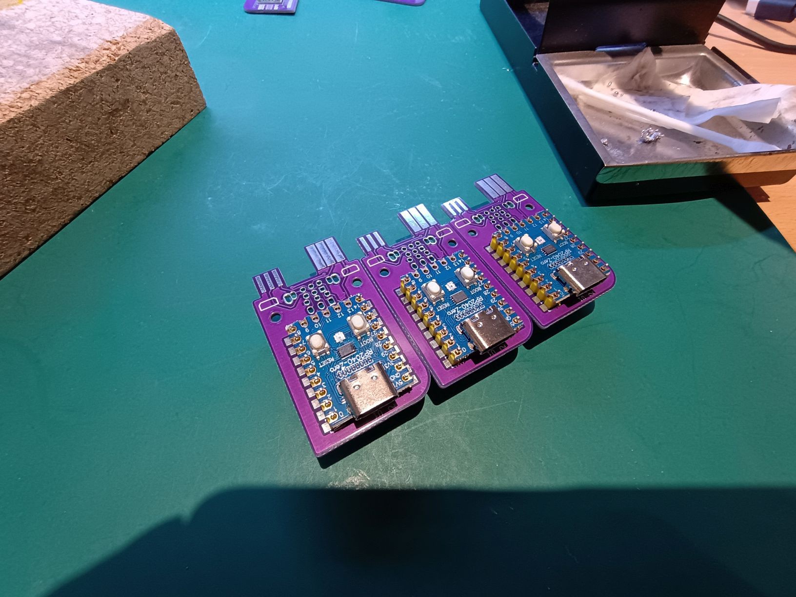
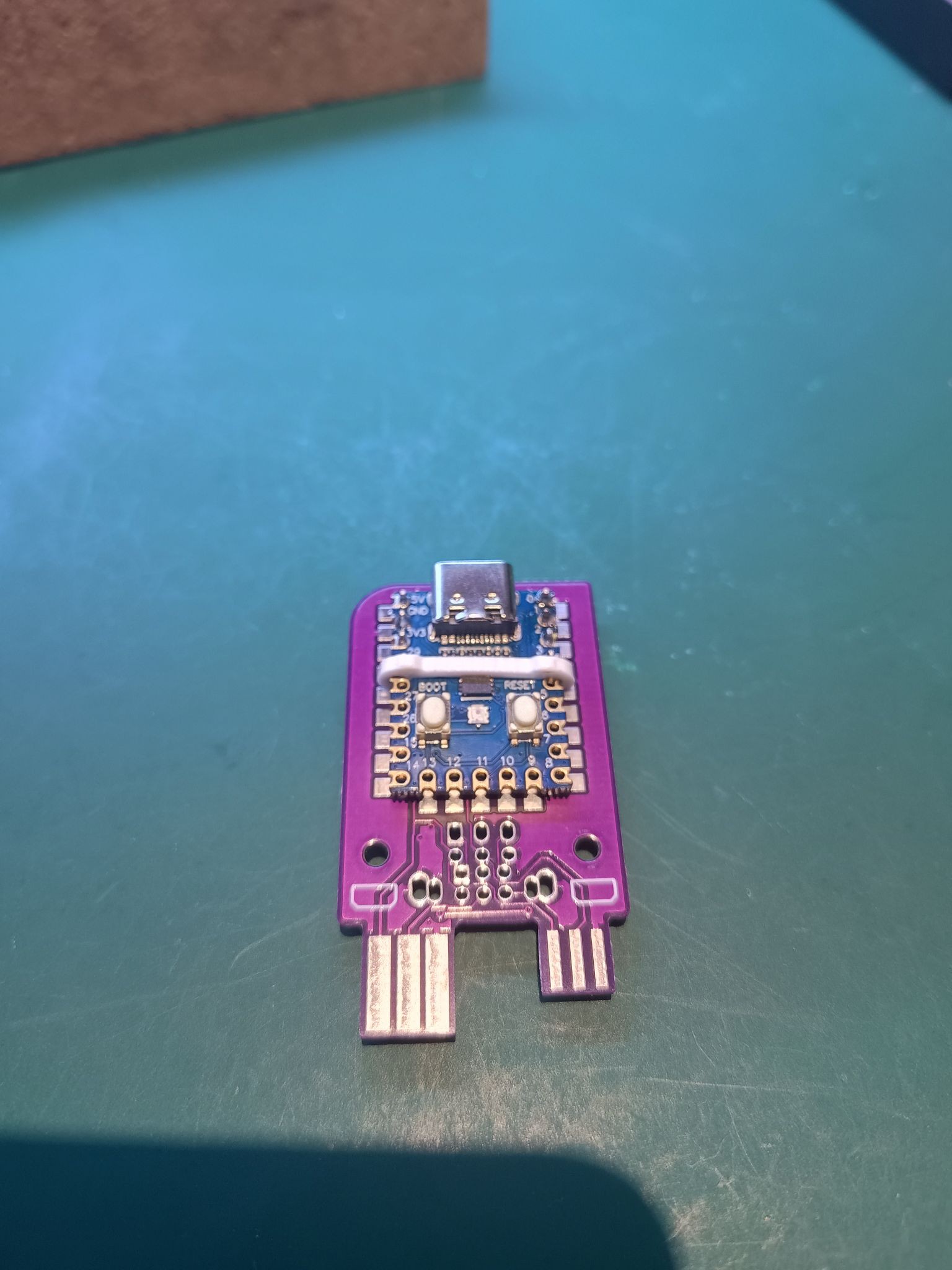
Again we have to do some non-standard soldering. Insert two rows 1x9 headers, long end first, to the game-boy-zero-link-board PCB.
Place the RP2040-Zero board on the short end of the headers on top.
Next we solder the pin header to the RP2040-Zero board. Not all the pins of RP2040-Zero are used. I opted to not solder all the pins. - solder the first four pins: PIN1 PIN2 PIN3 PIN4 - solder the last three pins: PIN21 PIN22 PIN23
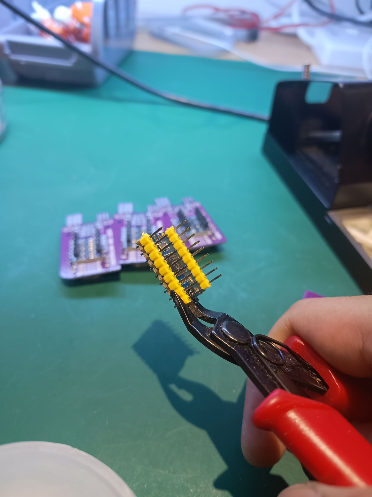
We want remove the unsoldered pins and remove the plastic shroud. The method that worked for me is to use a wire cutter with a flat side. Work on the pins that you just have soldered in. Have the cutter's flat side close to the PCB and gently apply force. This should force the plastic shroud to move up and way. You should be able to pry off the plastic shroud with the unsoldered pins from the RP2040-Zero.
With only 7pins left on the RP2040-Zero board, we can start to solder to the game-boy-zero-link-board PCB.
Start solder one corner. Try to align the RP2040-Zero board. This can be a bit tricky as the you might find that the RP2040-Zero's tallest component is the SOT23 component underneath the USBC connector. Take your time and try to keep the RP2040-Zero parallel to the game-boy-zero-link-board PCB.
4
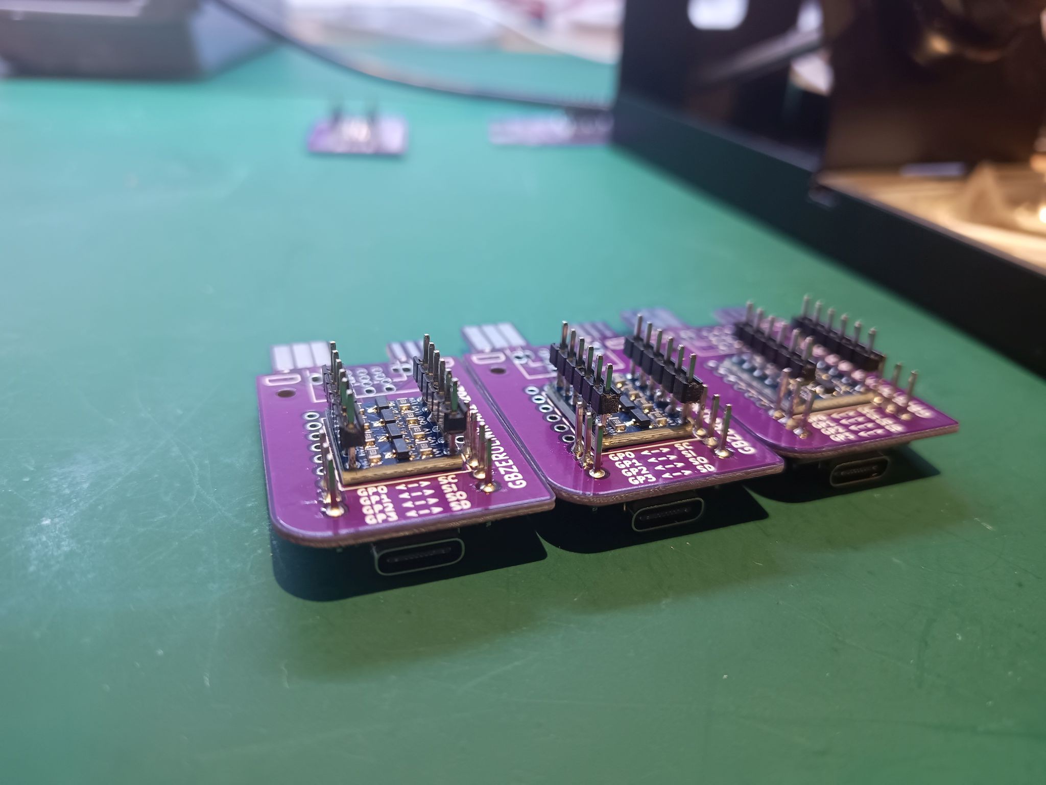
PCBA - Trimming the headers
This is my least favorite step. We need to trim the headers. My cheap wire cutters got damaged doing this. The header pins are quite hard and damaged the cutting edge. Please don't risk your valued cutters!
5
CASE - overview and prep
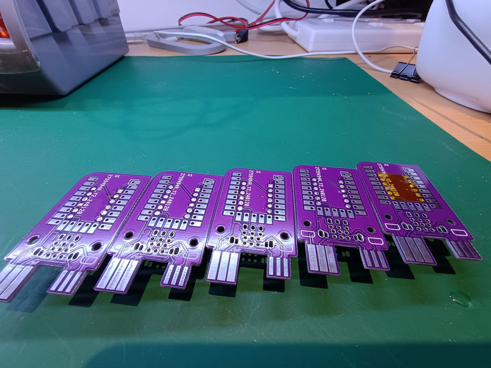
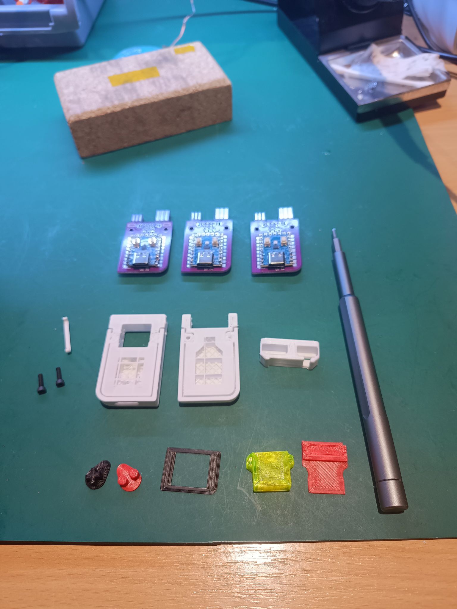
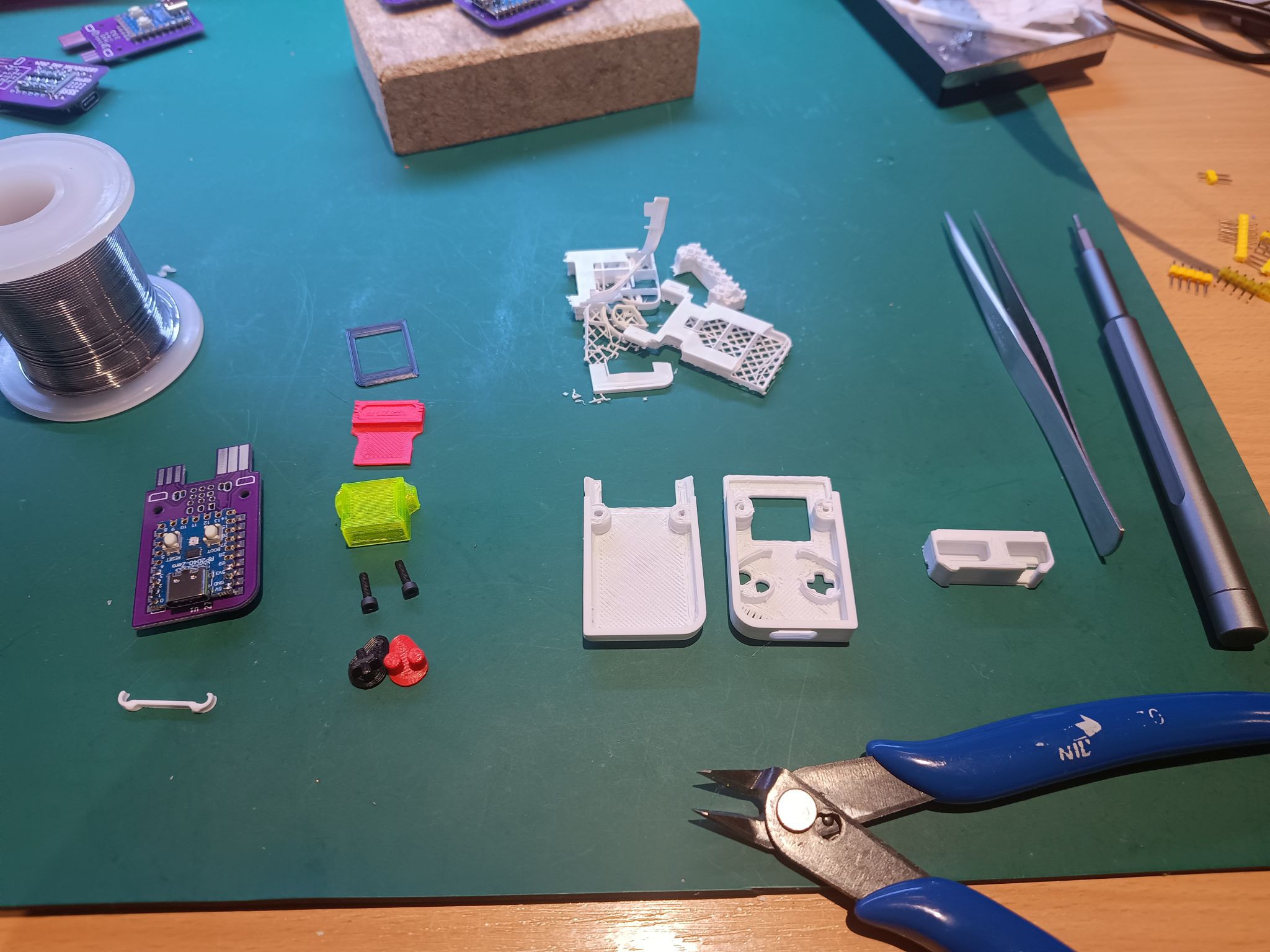
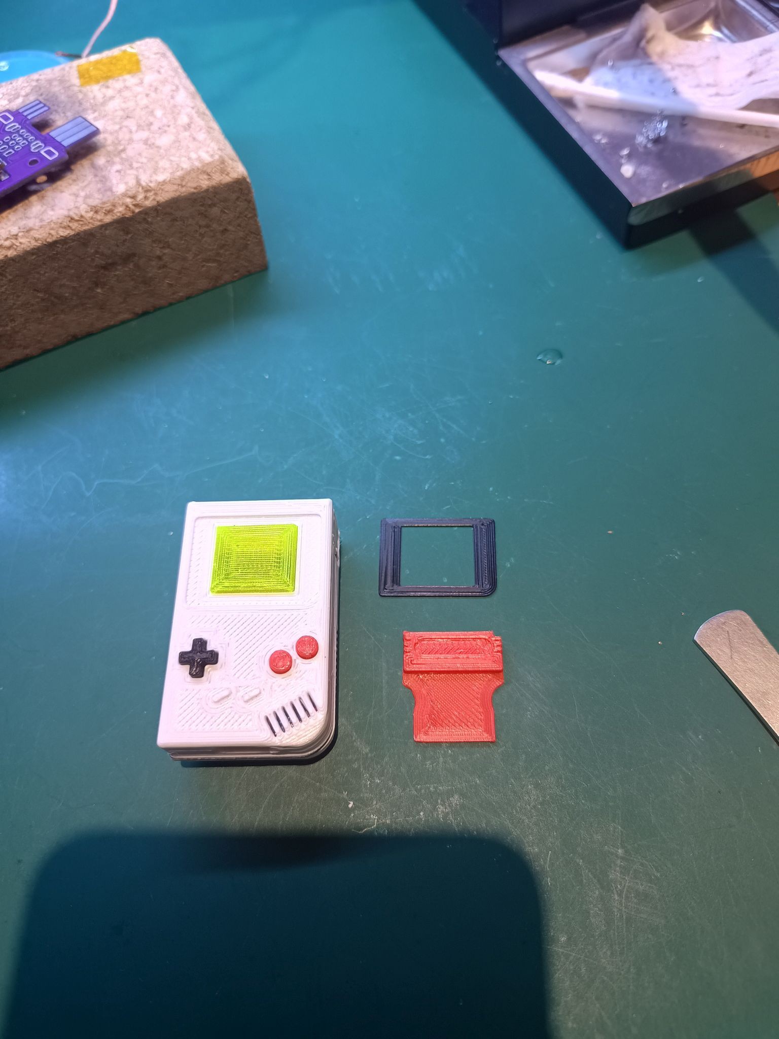
Here is an overview of the 3D printed part needed for the case assembly. Here I've printed all parts are printed in PLA with exception LCD screen: PETG.
Print support is used for the Top and Bottom, these need to be removed first.
6
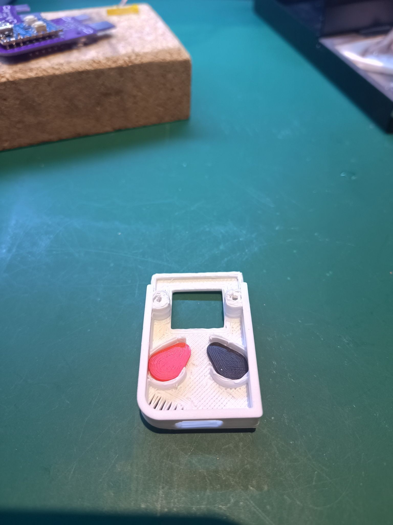
CASE - buttons
Insert the buttons in the Top case.
Add the small clamp across RP2040-Zero board between USBC port and the small chip. Align it closer to that small chip. This clip will helps the buttons to pivot and redirect the pressing-force to the buttons on the RP2040-Zero.
7
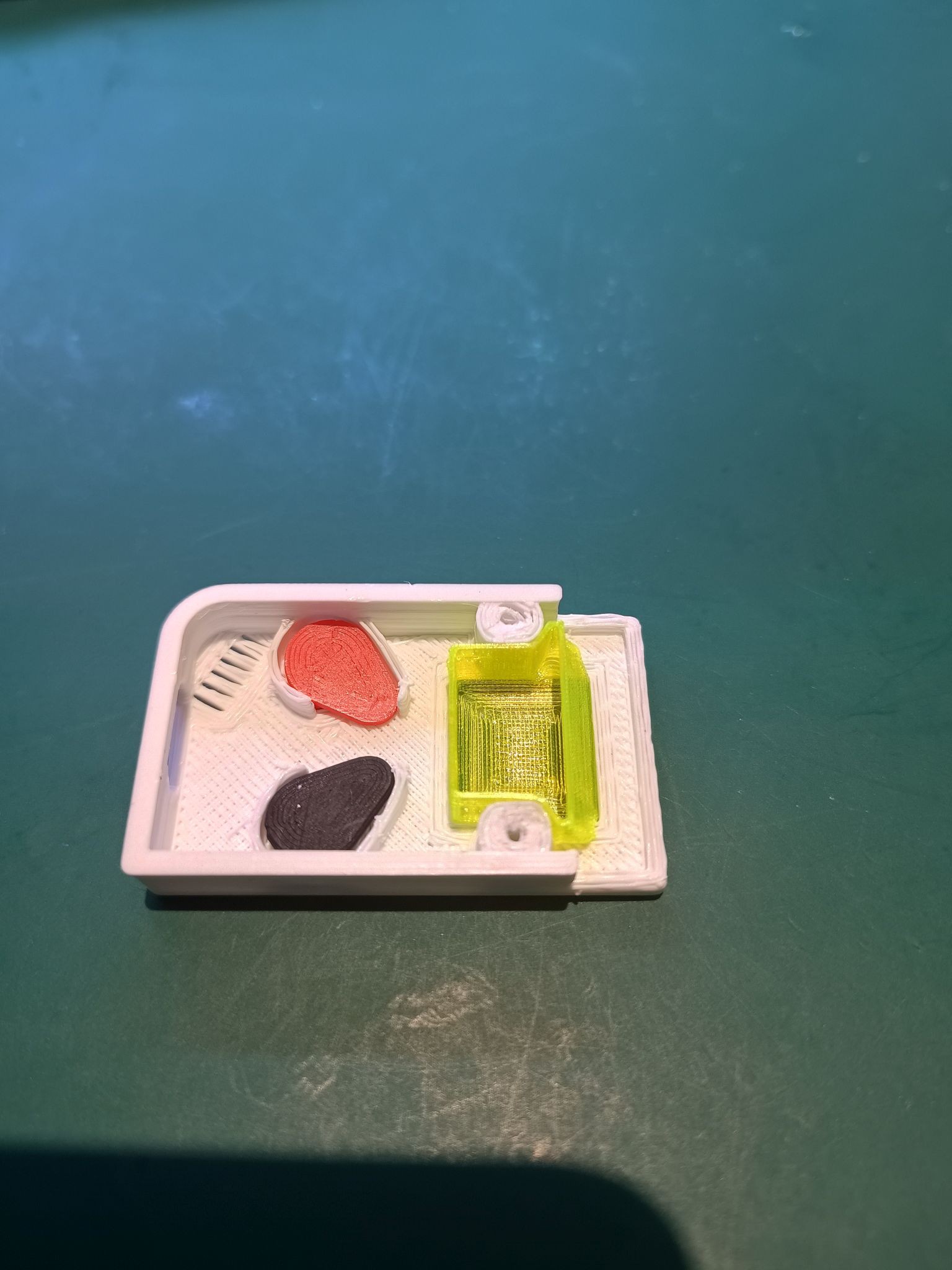
CASE - LCD
Insert the LCD part. This part I've printed in PETG as I happened to have it in translucent yellow. I've printed this part in "vase mode" as that come out in an acceptable quality from my printer. Bottom consists of two layers, which makes is sturdy enough. The translucent PETG allows the RGB light still to come through.
8
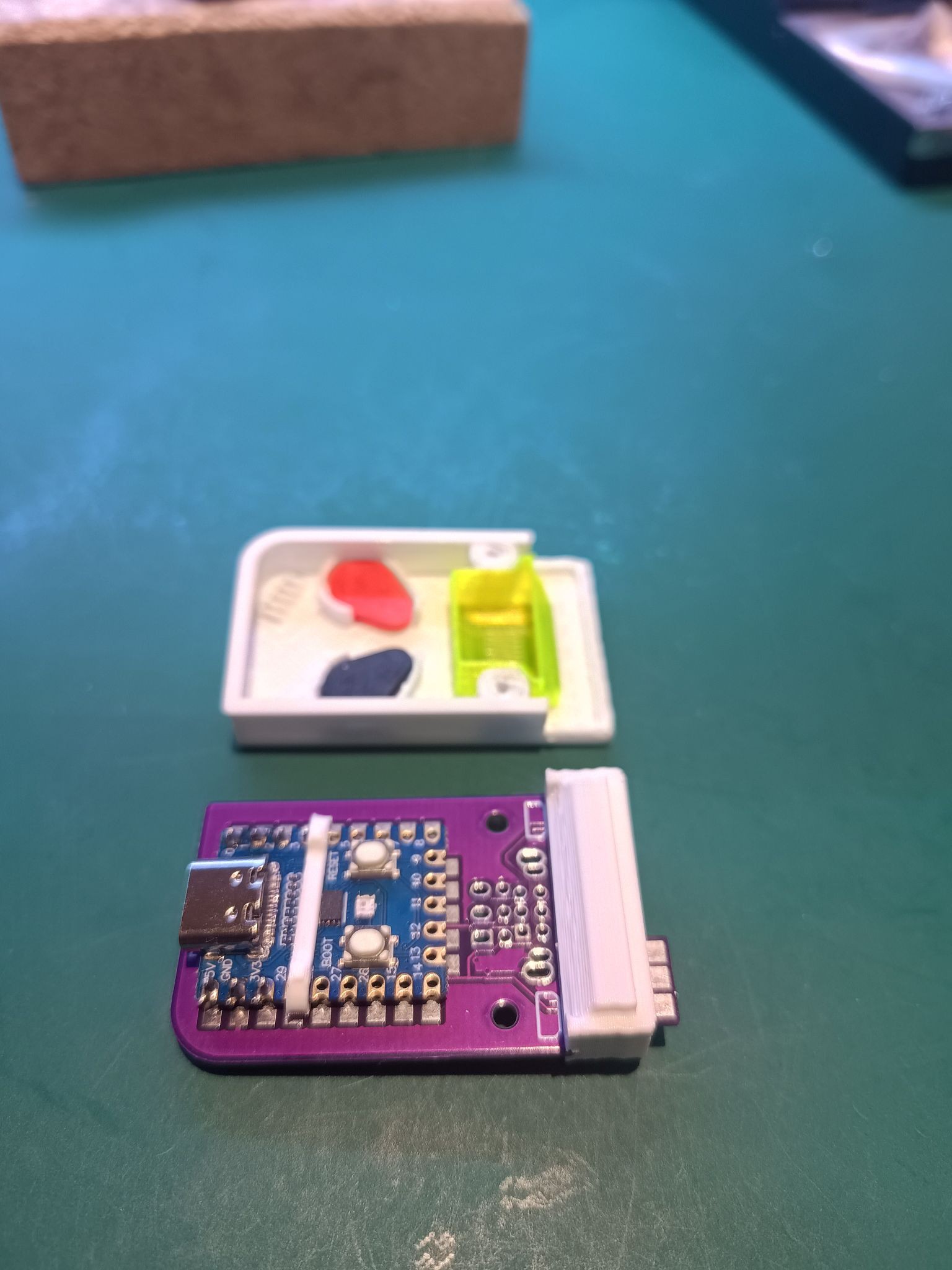
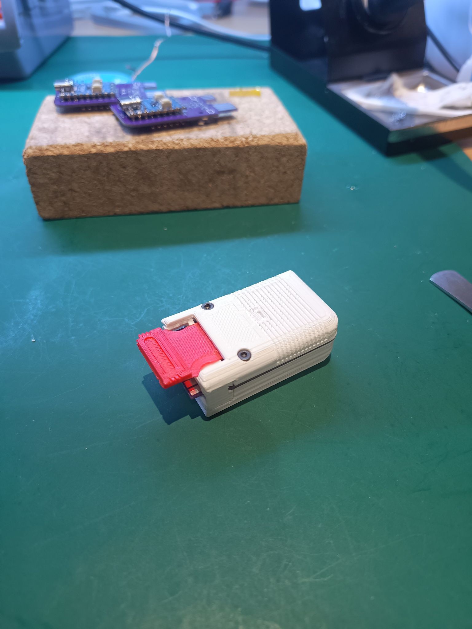
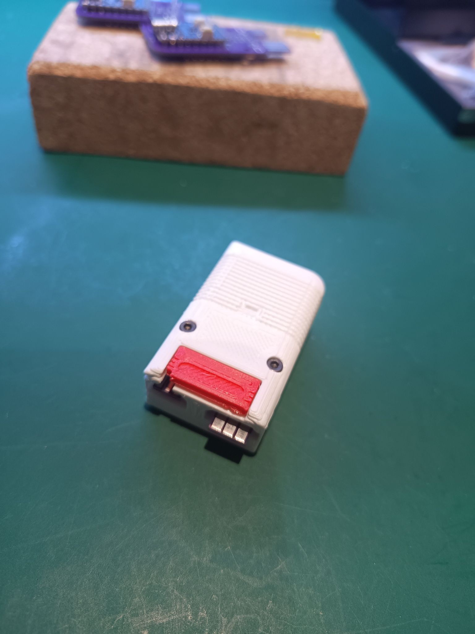
CASE - Link port housing
Insert the Link port housing over the PCB edge connector. Mind the orientation.
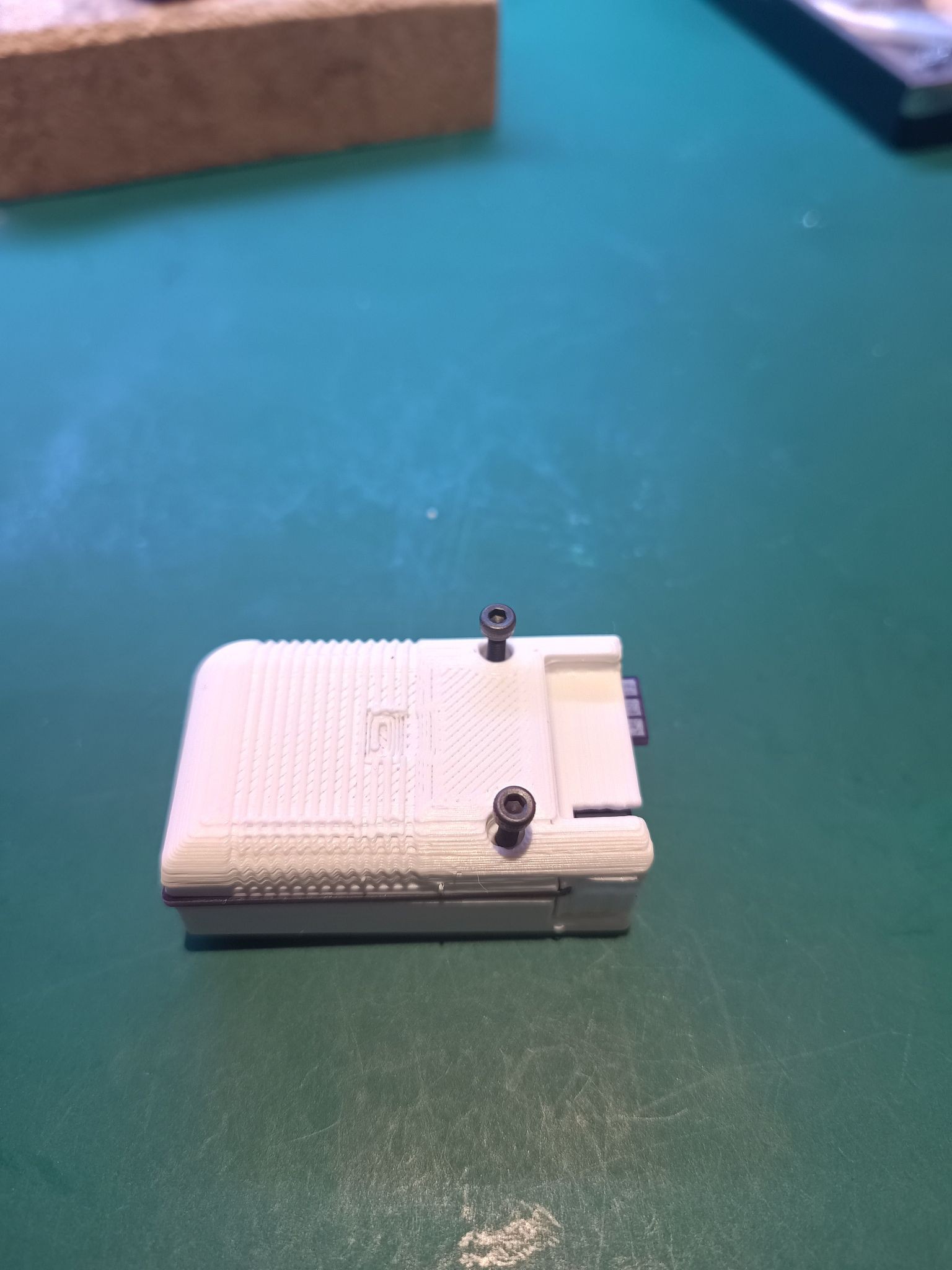
We slide the PCB, USBC port first, in to the Top case. Check if all things line up, like the LCD and Link port housing.
Close the
9
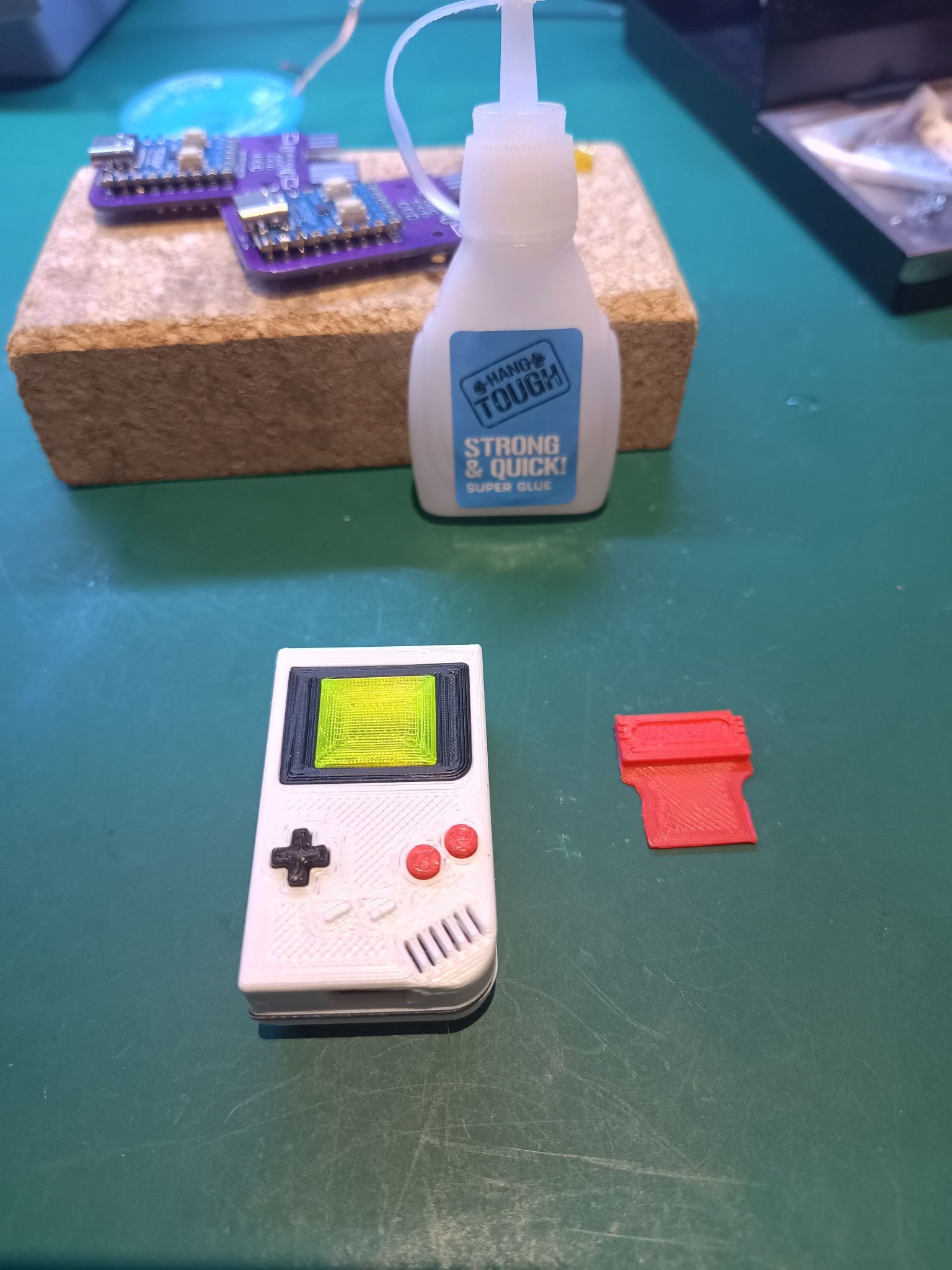
CASE - LCD frame
We can finish the assembly with the LCD frame. A small amount of super glue might be needed to keep it in place.
Discussions
Become a Hackaday.io Member
Create an account to leave a comment. Already have an account? Log In.