Close
0%
0%

Stereo Polarimetric 3D Scanner

Using Lego, a Raspberry PI and Stereo Polarimetric images to create high quality 3D scans.

Public Chat
Similar projects worth following
I've never done a 3d scanner before, never even touched stereo disparity, but I did read a paper once on how they combined a polarimetric camera with a stereo camera to achieve better results, and I think I know a way to retrieve surface normals from a polarimetric stereo pair. So this is me giving that a go...

Surface Normals from Stereo Polarimetric Images

A single polarimetric image gives us information on the polarization angle, per pixel. With the angle of polarization we can calculate the Plane of Incidence. This plane contains the surface normal and the propagation vector of the incoming radiation. We can't calculate the surface normal from just the polarization angle / plane of incidence in a single image.

However, if you use 2 images that look at the surface from different angles, you get 2 Planes of Incidence. The intersection of these 2 planes is a single line. Because this is the only line shared between the 2 planes, and because each of the planes holds the surface normal, the surface normal must equal the intersection of the 2 planes.

It looks something like this. Given 2 cameras, red and green, we show the plane of incidence from both viewpoints. Because of how reflection works, the line between the sensor and the surface also lays in the plane of incidence, which is why this plane shows up as a line for the sensor, corresponding to the angle of polarization.

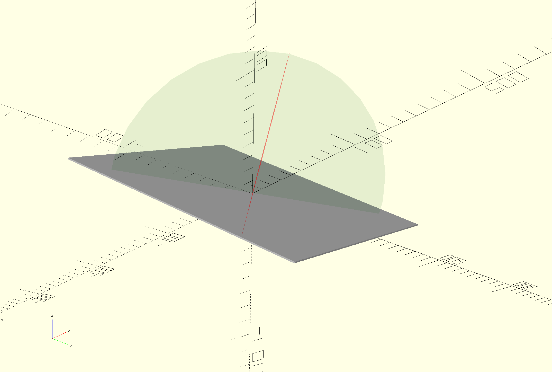
View from the red camera. Ignore the green circle, this is the plane of incidence for the green camera.

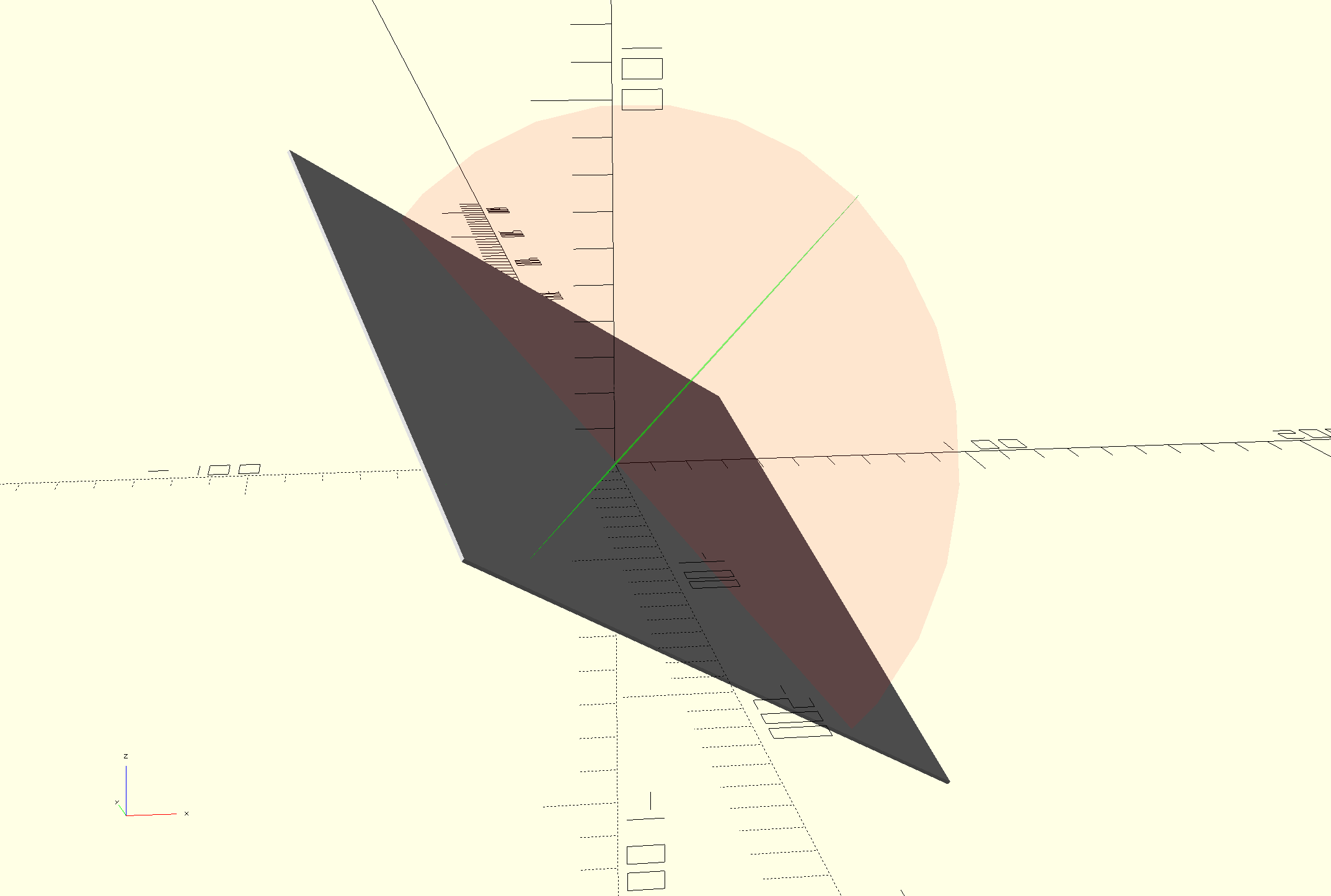
View from the green camera. Ignore the red circle, this is the plane of incidence for the red camera


Now that we have the polarization angles for both cameras, we can use the intrinsic parameters of the camera to project a ray to the pixel and calculate the plane of incidence. For both cameras we get a plane, and for each plane we calculate the normal to the plane (both of which are tangent to the surface). Finally, we take the cross product of these normals (tangents) to retrieve the surface normal.

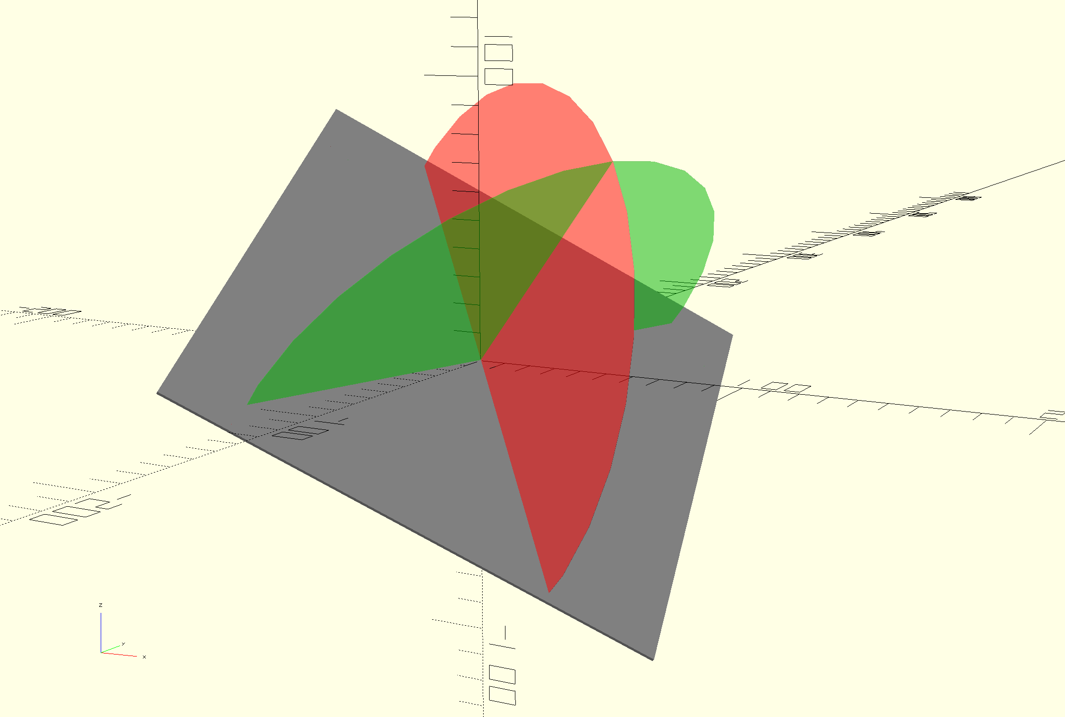
The surface normal is equal to the intersection of the 2 planes of incidence


Now, there is a caveat: when the planes of incidence become closer in terms of angle with respect to each other, opposed to (ideally) orthogonal, any noise in the signal will have a larger effect of the calculated surface normal. We offset this by using the feature of cross products that the absolute value of the vector decreases as the angle between the 2 source vectors decreases. We use this as a measure of "confidence" or "weight".

  • Lego + Hall Sensor

    E/S Pronk06/09/2024 at 09:35 0 comments

    For this project I wanted to use hall sensors instead of a physical switch for sending a trigger at certain angular intervals of the polarization filter. I ordered magnets with a diameter of 5mm and a length of about 8mm, which, after a bit of drilling, fit inside a lego hole (which is D=4.8mm). Now I have a magnet passing a hall sensor 12 times per rotation which feeds into an ESP32, which converts it to a single shot PWM trigger signal for the camera (exposure time = duty cycle to be set with potentiometer).

View project log

Enjoy this project?

Share

Discussions

hoesel wrote 06/03/2024 at 12:08 point

out of curiosity, do you have a link for me that explains how to take a single polarimetric image?

  Are you sure? yes | no

E/S Pronk wrote 06/03/2024 at 20:23 point

Hey, yes. Actually I have a project that does just that: https://hackaday.io/project/177723-lego-raspberry-pi-polarimetric-camera

  Are you sure? yes | no

hoesel wrote 06/03/2024 at 22:46 point

great results already.  The images are taken sequentially, so why not move your single camera 100 cm sideways and take another set. Basically the same as with your stereo plan, but with a larger base. Saves an extra camera.

  Are you sure? yes | no

E/S Pronk wrote 06/04/2024 at 00:12 point

Well, sure that would be a nice proof of concept for the math, but I kind of already did that with an actual polarimetric camera. It was quite a hassle to get the extrinsic parameters right every time I moved the camera. This could perhaps be resolved by using a solution like a realsense T265, I will probably add that anyway come to think of it, as it would allow me to walk around the object scanning it.

As for saving the extra camera, the cameras have already been ordered, global shutter, external trigger, YUV @ 60FPS over USB3, and I think it will make my life easier for now to stick with dual cameras. But your suggestion does give me some inspiration on what I could do for version 3, I'm thinking not so much about moving it 100cm and make 2 pictures, I'm thinking about shooting a video with the T265 attached, and then resolve the 3d shape from all the frames, each having a different view point (given by the T265 in world coordinate system) and a different polarization angle... :+1

  Are you sure? yes | no

Does this project spark your interest?

Become a member to follow this project and never miss any updates