Clyne
Clyne-
Rev 2 design
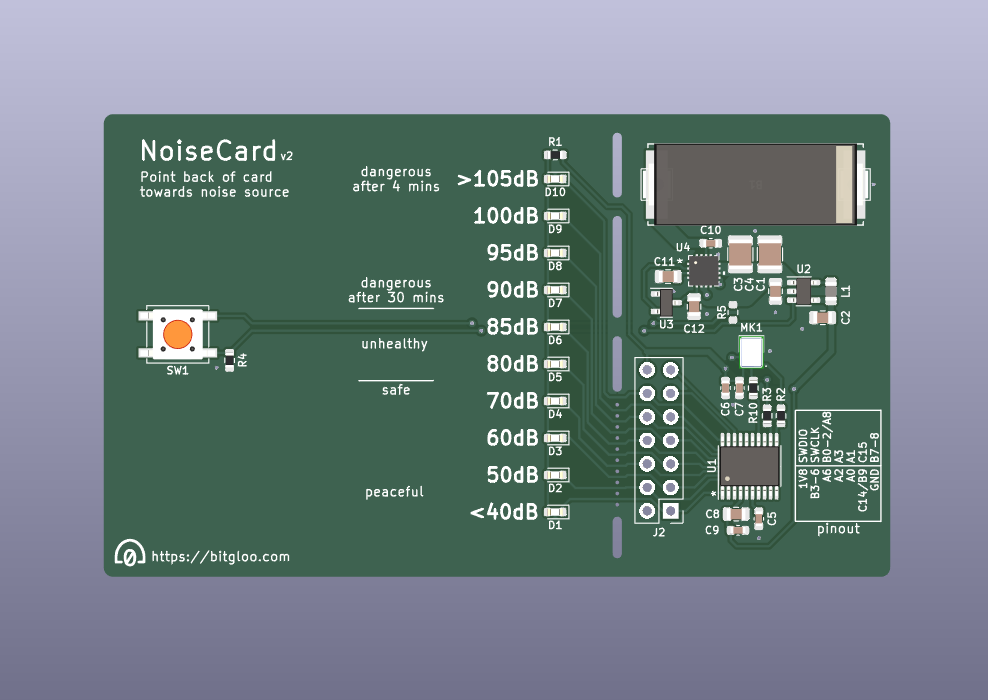
06/29/2024 at 19:47 • 0 commentsI've been working on a revision to the NoiseCard PCB in the pcb-rev2 branch of the project's repository. I'm fairly happy with its current state, so I'd like to share how the board looks and what's been changed:
![]()
Concept for rev2 design Energy Harvesting
An energy harvesting circuit has been added based on the NEH2000BY. This means that an energy store can be built up while the NoiseCard is in any ambient light conditions, as opposed to the previous design which practically required constant direct sunlight.
This chip is optimized for solar cell harvesting and can store energy at a rate of up to 2 milliwatts, almost reaching the power requirements of the NoiseCard while it's powered on. Paired with the new capacitor storage, the NoiseCard should be able to always provide enough energy for general usage even in low sunlight or indoor areas.
Larger capacity capacitors
After a thorough search, I came across small surface mount supercapacitors like the CPH3225A. They're much more dense than the current tantaulum capacitors, with a smaller physical size and a larger capacity of 11mF at a rated voltage of 3.3V. This should lead to a 12x improvement in possible run-time over the previous setup! The cost increase for this is less than a dollar per capacitor, very acceptable.
0.1" IO header and breakaway section
To make the NoiseCard repurposable, I routed all microcontroller pins through a 0.1" header and added a breakaway strip. This lets you remove the "business card" part of the PCB, including the on-off button and LEDs, leaving you with a solar-powered microcontroller with 10 GPIO pins. All you need from here is an SWD programmer (present on nearly all STM32 development boards) and a quick solder (shorting R5 to keep the system "on", or add some other on-off control) and you're free to start tinkering!
Pushbutton on-off control
The previous design used a slide switch... I don't like it. I just found it to be very bulky and rough on my finger. With a thin tactile button, all you'll need to do is lightly press down and the NoiseCard will power up.
Want one?
If low power and solar harvesting interests you, then maybe you'd like to have a NoiseCard for yourself :)
I may sell a batch on Tindie if there's enough interest, let me know if you are. I'll at least order a small run of this design sometime soon and see how the card's performance improves.
-
NoiseCard testing
06/18/2024 at 00:11 • 0 commentsI finally got around to uploading some videos on Youtube of the NoiseCard doing its thing. I'm pretty satisfied with its performance overall, but long-term a second iteration of the board is certainly needed.
Here's video no. 1 below! In the sun, the card works great. The LEDs are more noticable in person too, I promise.
As I continued with testing, it became apparent that the solar cell needs pretty direct sunlight to produce adequate power for the microcontroller. This comes down to two reasons: the cell feeds directly to a 1.8V switching regulator, so a voltage greater than 1.8V must be continuously present; second, the large capacitors are still only 660uF total, meaning maybe a couple of seconds of runtime once the sun goes away -- if they're fully charged.
It's sunny this time of year though, so more testing:
Measuring at least 80dB on a popular city street (Street No. 2, near Bloor/Yonge in Toronto) is concerning. The microphone's accuracy has checked out too -- during development I made sure performance was consistent with my other noise-monitoring project; both of these were built off of ESP32-I2S-SLM's reliable algorithms.
Even louder than that street though is the city's subway. For this test, I substituted a small coin cell battery in place of the solar cell: a CR1225. Taped to the card, it doesn't protrude much further than the cell. The wires that contacted the cell were a bit loose however, so the LED indication is a bit sporadic:
Overall, the NoiseCard has a lot of potential. To remedy its power supply issues, I'm looking into better energy storage (in the form of SMD supercapacitors) and an energy harvesting circuit to get as much power out of the solar cell as possible. The circuit would boost the cell's voltage over 1.8V so the system can run and charge in lower light conditions. Stay tuned for an update on that...
-
Firmware overview
06/11/2024 at 22:00 • 0 commentsThe NoiseCard's firmware is entirely available from the project's repository. It's fairly compact with the main source file containing less than 200 lines, but those lines are fairly busy in what they do. Rather than walk through it line-by-line, I'll just talk about each component of the firmware and what it contributes:
ChibiOS
ChibiOS is an awesome project that provides an open-source real-time operating system (RTOS) and hardware abstraction layer (HAL). This system has amazing STM32 support and easy to use APIs, so it's often my first choice for projects like this. Here's an example of how the microphone (I2S) driver is used:void i2sCallback(I2SDriver *i2s); std::array<uint32_t, I2S_BUFFER_SIZE> i2sBuffer; I2SConfig i2sConfig = { /* TX buffer */ nullptr, /* RX buffer */ i2sBuffer.data(), /* Size */ i2sBuffer.size(), /* Callback */ i2sCallback, /* Settings for the STM32's I2SCFGR and I2SPR registers... */ 0, 0 }; // Then, just two lines to start the microphone: i2sStart(&I2SD1, &i2sConfig); i2sStartExchange(&I2SD1); // The callback will now continuously fire as data comes in. This occurs as each // half of the buffer is filled, so data can be processed in one half while the // other half receives new data.The RTOS comes in a lightweight version called "NIL" that I used initially given the little space available on my microcontroller (32kB flash, 8kB RAM). Only two threads were used: a worker thread that managed decibel calculation and LED indication, and an idle thread that could enter the MCU's sleep mode while it waited for more samples to come in. The interrupt handler for the microphone would filter and equalize the incoming data, using a semaphore to wake up the worker thread once enough data was processed.
This system worked well, but as I optimized for lower power usage I ended up scrapping the threads and RTOS component. The code is simple enough to be a little "superloop": sleep until new data is ready, process the new data, display the result, repeat:
for (;;) {
    // The "Wait For Interrupt" (WFI) instruction puts the processor to sleep until
    // an interrupt fires. With SLEEPONEXIT, the processor will return to sleep
    // after the interrupt completes.
    // So, the code below __WFI() will not excecute until the SLEEPONEXIT bit is
    // cleared, which is done by the microphone's interrupt once enough samples
    // have been processed.
    SCB->SCR |= SCB_SCR_SLEEPONEXIT_Msk;
    __WFI();

    // Since microphone data collection is ongoing, use std::exchange() to retrieve
    // the calculated sum_sqr and count values and simultaneously reset them to 0.
    // sos_t is a type for the software floating-point implementation.
    const auto sum_sqr = std::exchange(Leq_sum_sqr, sos_t(0.f));
    const auto count = std::exchange(Leq_samples, 0);

    // Calculate the final decibel (dBA) measurement.
    const sos_t Leq_RMS = qfp_fsqrt(sum_sqr / qfp_uint2float(count));
    const sos_t Leq_dB = MIC_OFFSET_DB + MIC_REF_DB + sos_t(20.f) *
        qfp_flog10(Leq_RMS / MIC_REF_AMPL);

    // Finally, round the measurement to an integer and display it.
    const auto n = std::clamp(qfp_float2int(Leq_dB), 0, 999);
    blinkDb(n);
}
This ended up reducing power draw by 12% or so, most likely due to the removal of the RTOS's periodic tick and other overhead.
ESP32-I2S-SLM
ESP32-I2S-SLM provides code to accurately measure decibels with the SPH0645 microphone. For this project, I re-implemented parts of it in modern C++ and adapted it to run on the STM32 microcontroller. The code can be found in sos-iir-filter.h.
This library works by implementing second-order sections (SOS) infinite impulse response (IIR) filters. Apart from the filtering algorithm, structures are defined with coefficients for the microphone's frequency response (to flatten the response for more accurate readings) and to apply either A- or C-weighting for calculating dBA or dBC values.
These calculations result in two values: a sum of squares of all of the processed samples (sum_sqr) and a count of how many samples are included in that sum. The microphone interrupt increments these values over time, then the main loop can simply use these two values to produce the final reading.
Qfplib
The biggest drawback from using the chosen microcontroller is its lack of a hardware floating-point unit. Since all of these calculations depend on decimal-point accuracy, floating-point (or fixed-point) processing is a necessity. The GCC compiler provides a software floating-point implementation, but it's dreadfully slow. This led me to Qfplib, which implements floating-point operations that are optimized to specific architectures like the STM32G0's ARM Cortex-M0+ core.
The functions are written in assembly, with a C header for interfacing. For ease of use, I wrapped these functions in a C++ class called sos_t that had operator overloads for addition, division, etc.
With this library, processing time was significantly reduced. I put that towards more time to sleep the processor, but it also could have gone towards processing more microphone samples: since this operation is still so slow, the firmware only takes part of the microphone samples it collects to calculate decibel readings. At the moment, this is actually just 16 samples per 512 sample block -- 512 samples at our 48kHz sampling rate gives us enough time to process 16 samples and return to sleep mode for a useful amount of time.
A faster option would be a fixed-point math library, which uses integer representations of decimal numbers. I just haven't found a workable solution yet; I believe part of the issue is the wide spread of values that this code requires, from 18-bit microphone readings to many-decimal values in the filters' coefficients.
STM32 provides fast, low-power microcontrollers that include hardware floating-point units, but those are at least twice as expensive as the STM32G0.
Low-power configuration
The final piece to this firmware is how it achieves its low power operation, which I last measured at 1.75mA @ 1.8V. This is what it came down to:
Lowering clock speeds
The microphone needs at least 3MHz to run at the desired 48kHz sampling rate. I went with a processor clock of 16MHz to balance low clocks and fast execution of the code. I did experiment multiple times with running fast and sleeping more often (the MCU runs at up to 64MHz), but I could never get lower than what I achieved with 16MHz.
ChibiOS's mcuconf.h header made configuring clock speeds easy and quick.Reducing processor power draw
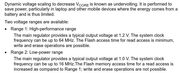
First, I chose to run the entire NoiseCard at 1.8V since the microcontroller and microphone both supported it. Next, the MCU can internally run at two different "ranges":
![]()
The 16MHz processor speed I chose gives the best performance possible in Range 2. Remaining in Range 2 vs. Range 1 typically saves around 20% of processor power (see the datasheet).
An additional chunk of power can be saved by running code from SRAM rather than Flash. Since the microphone interrupt handler was running most often, I marked its functions to be placed in SRAM. This also included taking pieces of the Qfplib math library and placing them in C functions so they could also be placed in RAM. This saved at least 0.1mA of average consumption.
Sleep modes
Of course, entering sleep modes whenever possible made a huge difference in power draw. This is done in the firmware through the Wait For Interrupt instruction which corresponds to the "regular" sleep mode.
The STM32G0 can do even better with its "low-power run" and "low-power sleep" modes, but they require a system clock speed of 2MHz. Again, the microphone needs at least 3MHz to continuously collect data. If the system were redesigned, perhaps the mic could be run at 2MHz for a 32kHz sampling rate, though the filtering would need recalculations and new testing for accuracy. The processor couldn't calculate much at 2MHz either, so some dynamic frequency scaling (or hardware floating-point support) would also be needed.
When I first started working on the NoiseCard, its breadboard prototype was running at something near 7mA @ 3.3V or 23 milliwatts. With all of the above, the current NoiseCard is down to 1.75mA @ 1.8V or 3.15mW -- an 86% reduction! I'll bet that this could be pushed even lower, but for now it's more than enough to produce an accurate, low-power NoiseCard.
-
PCB Bringup
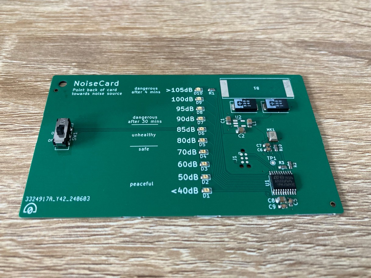
06/09/2024 at 20:29 • 0 commentsHere it is! The boards came out great:
![]()
Only one issue with this batch: L1, the inductor for the switching regulator, got a capacitor placed on its footprint (see it above near the unplaced U2). I apparently overlooked this when JLCPCB generated a BOM for me. Fortunately, I was able to pull a substitute off of some other boards.
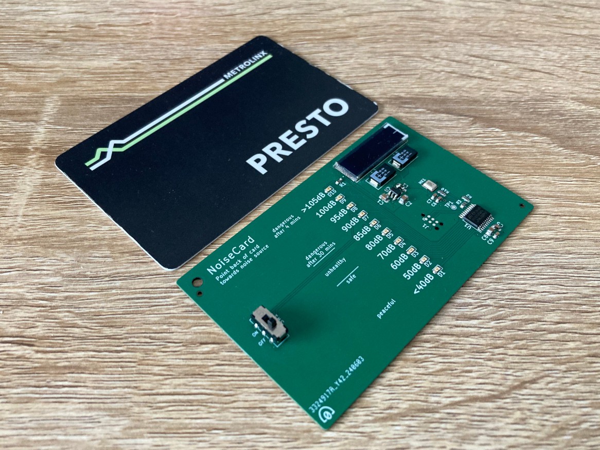
Here's a fully assembled board below with a regular card for comparison. The solar cell was a pain to solder on, with barely any room to heat solder between its underside pads and the PCB footprint. I tried a heat gun, but that started to melt the cell's coating before heating the solder below. For now, I just loaded solder onto the pads so I could heat it with my iron while squishing the cell down. In the future, I'd consider using through-hole pads that I can just fill up with solder.
![]()
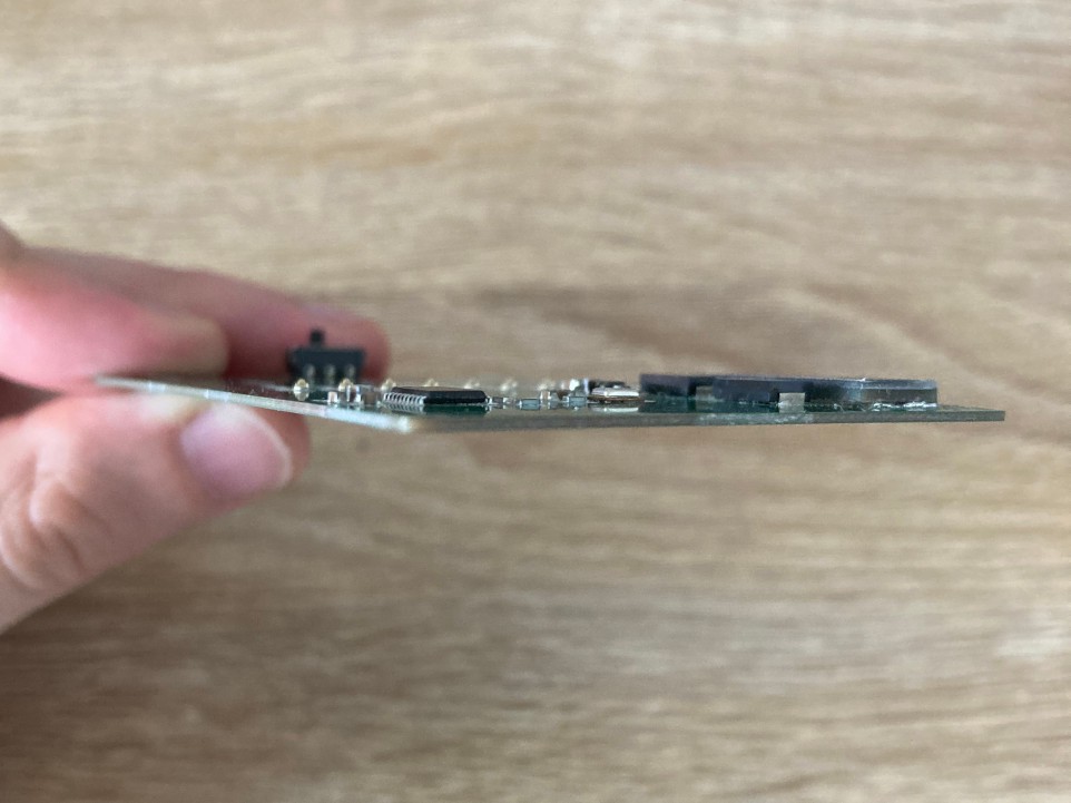
With the 0.8mm thick PCB, the card is overall very thin. It's 3mm thick including the solar cell, and a bit beyond that with the on-off switch. Another change to consider would be swapping the switch for a thinner tactile button.
![]()
For testing, I powered the microcontroller with an external power supply; either 1.8V on VCC or 2.5V at the solar cell. My programmer (an Olimex ARM-USB-OCD-H) connected to the MCU just fine, and I was able to flash firmware and get started on software bringup. I'll cover that and have notes on testing in the next post.
-
Layout and manufacture
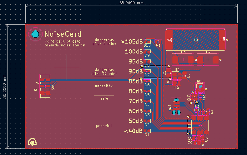
06/09/2024 at 14:26 • 0 commentsHere's the finished layout of the first NoiseCard:
![]()
First NoiseCard layout The design is fairly straight-forward, no minimum trace widths or impedances to worry about. The digital microphone means little worry about analog noise too. Some notes:
- Dimensions: 85mm x 50mm is slightly less than a "standard" business card, but this really doesn't need that much space. This is more of a production specification, but I also opted for a 0.8mm board thickness. The thinner board was no extra cost, and it helps make the PCB more of a card.
- On-off switch on the left lets you hold the card with your hand away from microphone port.
- Decibel scale: larger spread below 80dB since (I believe) most people would find those levels to be tolerable. If we're measuring over 80dB, we're more interested in precision to know how loud (and damaging) the noise is.
- Healthy/dangerous notes: I wanted to provide info on the card so users can understand more about noise levels and their potential harms. With half of the card empty, I would have loved to fill it up with info, studies, facts, etc, but coming up with all of that would have delayed sending this PCB to production. I just left these "safe", "unhealthy", and "dangerous" remarks to start; in the future, I might print a sticker with more info that could go over the PCB.
- Top-left hole: Maybe you can throw this on a keychain?
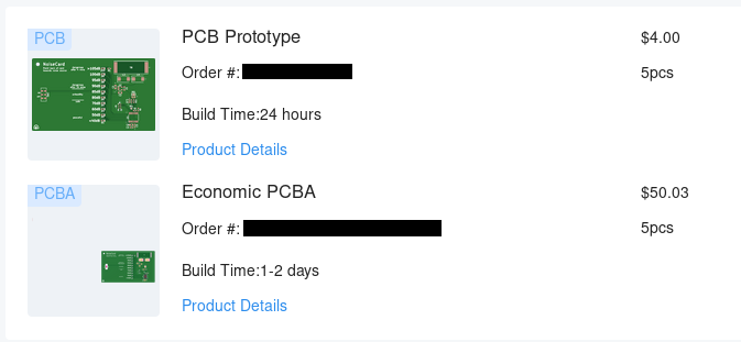
Production
I ordered PCBs and assembly through JLCPCB. I had previously ordered personal stock of the microphone, so it made sense to use that up. For five boards, it cost $4 for the PCBs plus $50 for the assembly (minus the solar panel and 1.8V regulator which were unavailable); about $11 per card.
![]()
Order through JLCPCB Next, we'll see how well these cards perform, and if the on-board solar power is enough to make them useful.
-
Schematic Design
06/09/2024 at 12:38 • 0 commentsI used KiCAD to design the PCB; it's awesome and open-source. There are only a few circuits needed for this PCB, I'll walk through them in sections:
The microcontroller (+ programming port)
I chose to stick with the STM32G031 microcontroller (MCU) since it gave the best balance of physical size, performance, and efficiency that I could find. Faster Cortex-M4 MCUs were larger and required more design effort, while other MCUs of the same physical size either lacked the I2S peripheral that the microphone required or consumed more power while idle or sleeping.
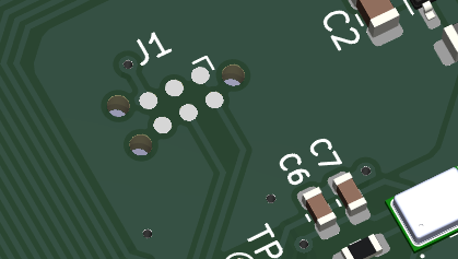
For a programming connection, I went the popular Tag-Connect header. It helps keep the design flat since it doesn't require any components, and it's easy for me to use since I'm familiar with it.
![]()
The Tag-Connect header (J1) is comparable in size to a few 0603's. Microphone
I'm using the SPH0645LM4H-B. The decibel measuring code I have is optimized for this specific part, so this choice is fixed.
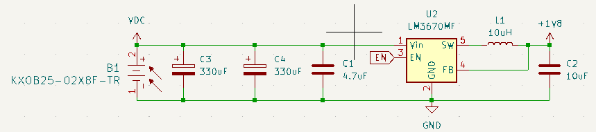
Solar and power regulation
I searched Digikey for small solar cells, and came across the manufacturer ANYSOLAR Ltd that has a wide variety of options. Given that the prototype can run on just 3-4mW of power, I thought the KXOB25-02X8F-TR would be a good choice. It provides up to 26.3mW with a size of just 23mm x 8mm.
Rather than using a bulky battery, I opted for a couple of large capacitors to provide some energy storage. The super-capacitors I could find were large and cylindrical, so I instead went with some 330uF tantalum polymer capacitors. They're SMD size, and two in parallel would provide a couple of seconds of run-time when fully charged -- enough time to take a decibel measurement, though I'd later learn that this was a bit short on desirable "battery" life.
Finally, I selected a fixed 1.8V switching regulator to power the MCU and mic. The LM3670 only needs three external components and runs at >90% efficiency while consuming just 15uA for itself.
![]()
The power circuit To control the system's power, I attached an on-off switch to the regulator's enable (EN) pin.
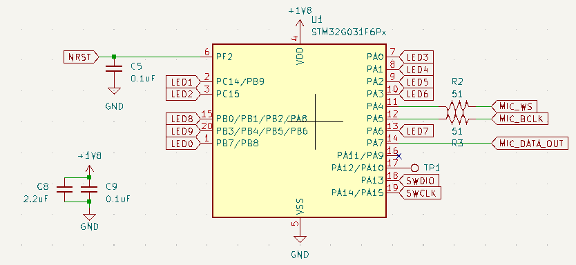
Decibel indication
This choice was probably the most difficult, with many trade-offs between complexity, user friendliness, and power consumption.
Option 1 was a shift register to control LEDs where each LED indicated a certain decibel threshold. This would have been used with the 8-pin MCU from the prototype. I tossed this idea since I would want more than 8 LEDs, and the added cost of shift registers vs. just an MCU with more IO pins wasn't worth it.
Option 2 was a monochrome LCD from Display Visions, a German company that makes low-power and easy-to-use displays. They have options that can run a a fraction of a milliamp, and having graphics on the business card would be awesome. I ended up turning this down though: their displays are expensive (i.e. I wanted this PCB to be inexpensive), they only come in through-hole packages, and they would add to both hardware and software design complexity.
So, I went with option three: 10 LEDs and an increase to a 20-pin MCU package. I found a bright and low-power LED option, the APTD1608LSURCK. It's an 0603 package that can achieve maximum brightness at just 2mA. Blinking these for a fraction of a second would reduce their power consumption even further without compromising on brightness.
With a forward voltage of 1.75V, I can also run them at a solid 1mA using a 51 Ohm resistor -- keeping the BOM short by reusing a value from the microphone circuit.
![]()
10 LEDs and the microphone use up nearly all of the MCU's pins -
Introduction
06/06/2024 at 00:12 • 0 commentsThe initial idea for this project spawned off of another that is using an ESP32 for continuous decibel monitoring. While the beefier ESP32 allows for wireless reporting of measurements, there's a price to pay in energy: 20mA or so of current consumption while recording from the I2S microphone, and a whopping 80mA while connecting to WiFi.
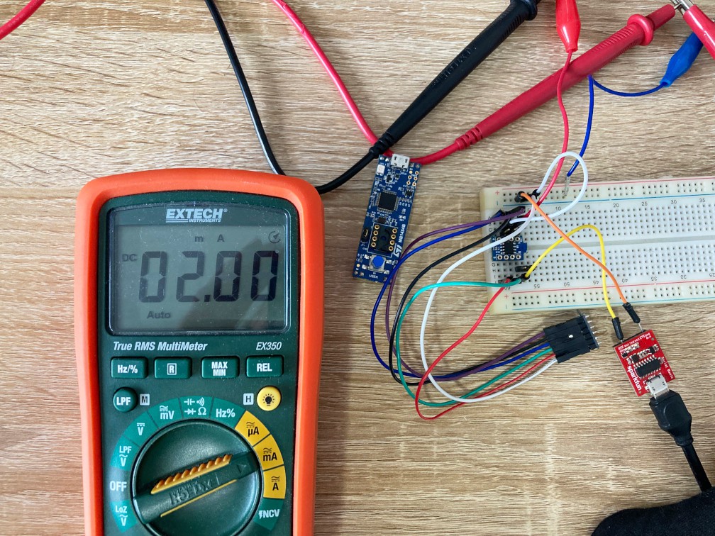
As a lover of ultra-low-power systems, I knew that microphone monitoring and decibel calculation could be done for a fraction of that energy budget. Searching for a viable low-power, low-pin-count microcontroller, I came up with the STM32G031J6: a tiny 8-pin SON package with a Cortex-M0+, I2S connectivity, and promising low power characteristics. I ordered its development board, the STM32G0316-DISCO, and began testing it with the microphone breakout board I had on hand.

The MCU, mic breakout, and a serial monitor After getting the system running with some code, it was clear that this could be very low power: down to 2mA at 1.8V -- less than 4mW! This was achieved through low clock speeds, optimizing calculations, and using an RTOS with sleep modes and interrupts.
![]()
Measuring current for the MCU + microphone Now with the rise of Hackaday's business card challenge, I knew it would be no problem to stick these two ICs onto a PCB. With such little power required though, I wanted to push the limits and run the circuit entirely off of solar power; no bulky battery, just a thin, light card that could be used anywhere (where there's light).
So, the next step is to design a PCB...