Close
0%
0%

Low-Cost Programmable Power Supply

Chinese "LM2596 DC/DC buck converter with voltmeter" + "some wires" + "Forth" = "programmable power supply"

Similar projects worth following
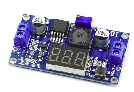
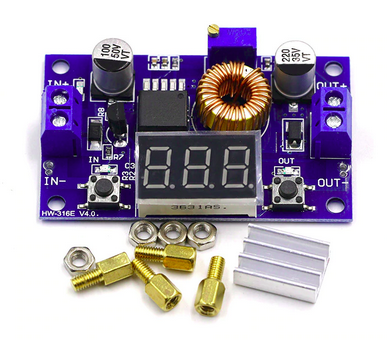
Programmable power supplies are important for test automation. This project turns a $1.60 Chinese DC/DC converter with µC-based voltmeter into hobby lab equipment. The price per unit is less than $2, and the conversion can be done in about 15 minutes!

So far, the following features have been implemented:
* modification instructions for a cheap DC/DC converter
* programmable output voltage and ON/OFF
* input and output voltage measurement (e.g. for display, safety, or closed loop control)
* Full programmability in an embedded scripting language
* U=f(t) time sequencing,
* character I/O with 2 keys and 3 digit 7S-LED display for user interface
* remote control, and interactive scripting through RS232

Code from the Hackaday "eForth for cheap STM8S Value Line gadgets" project is used, mastering of which will give you bragging rights. It's also possible to use this hack for simple automation, battery charging, or lighting.

Hackable DC/DC Converters

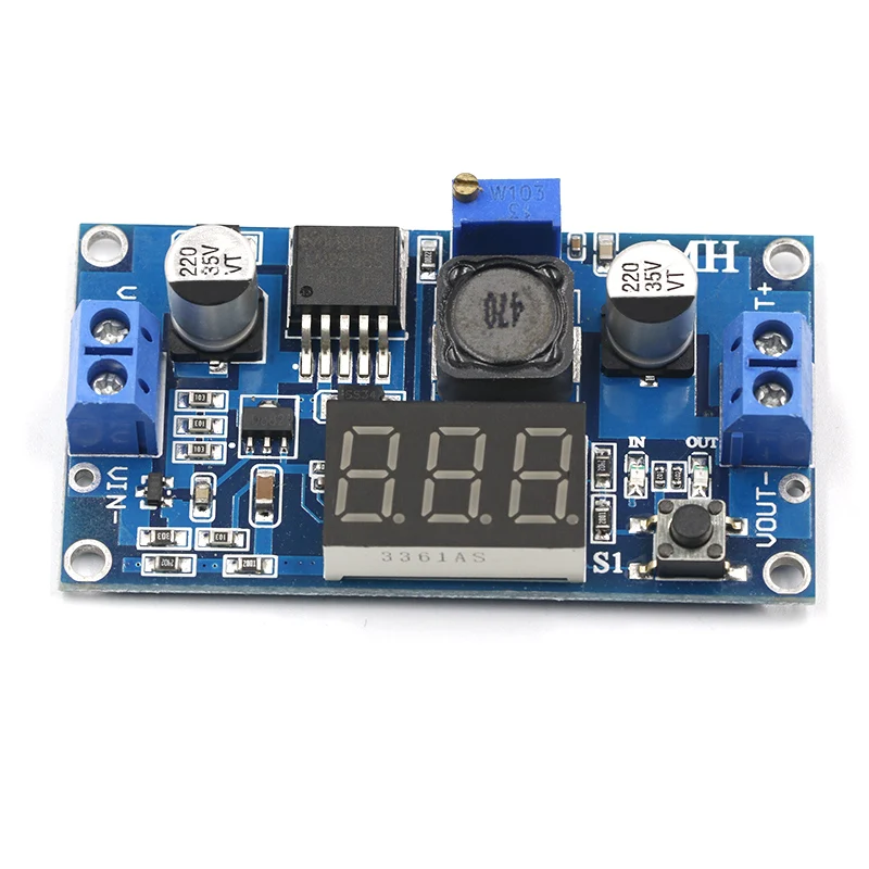
A quick search for "LM2596 DC 4.0-40 to 1.3-37V Adjustable Step-Down" on AliExpress presents a range of cheap DC/DC converters with voltmeter from $1.50. I discovered that the voltmeter uses a STM8S003F3P6, the low-cost µC that's the target of my first Hackaday project. The first specimen I hacked didn't have the most promising hardware design: it was necessary to solder patch wires to pins of a 0.65mm TSSOP package *).

The second one I ordered looked like this:
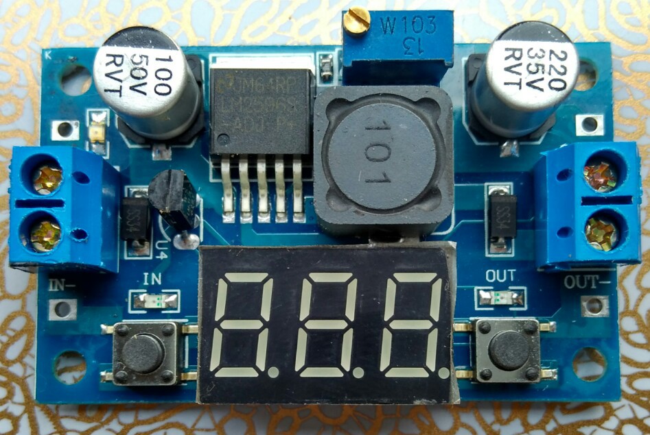
The first obvious thing, already visible on the vendor's pictures, is that the 7S-LED display nicely covers the voltmeter part including all the passive components.

*) Of course, it's still possible to remove the 7S-LED display, and use the pin as a breakout for no less than 11 GPIOs!

Under the Hood

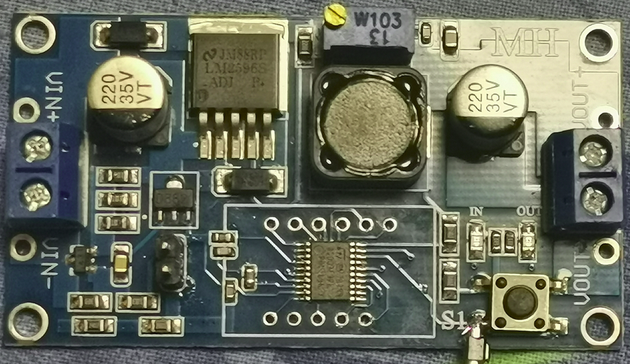
Underneath the LED display we find this nice arrangement:
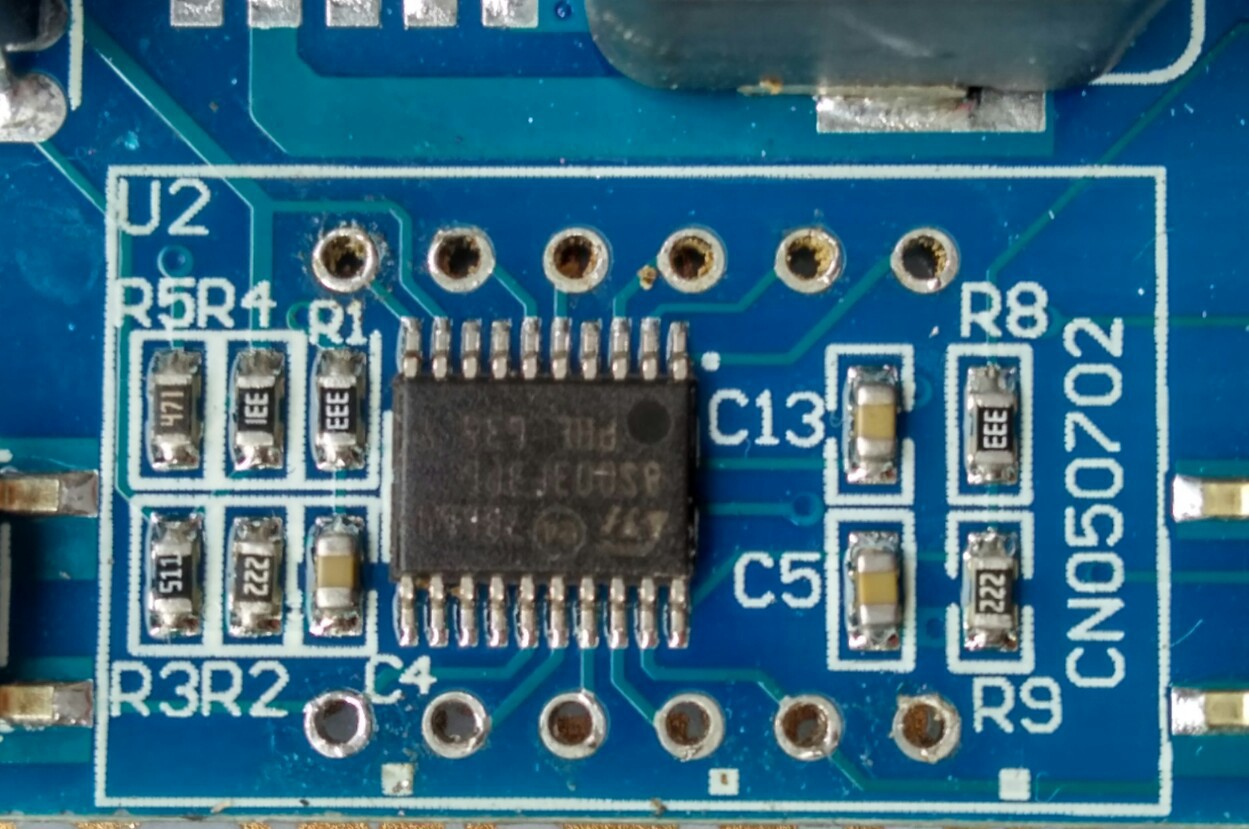
The LM317 in TO92 package is directly connected to the voltage divider R4/R3 (the LM317 lacks the recommended capacitor Cout, Cin is shared with the LM2596). C13 is connected to Vcap (STM8 1.8V core supply circuit). R1/R2-C4 and R8/R9-C5 are the "voltmeter inputs" (PC4 Vin, and PD3 Vout). R5 is connected to the green power LED.

PC3 is connected to LED "in", and PB4 to LED "out" without current limiting resistor (the same as the 7S-LED display). Like in the first variant, the "design" relies on the limited current driving capability, and on the surprising robustness of the STM8S outputs. The LED power dissipation is limited by a 4% duty cycle (there is a small risk of accelerated aging).

Isn't there anything else missing? Yes, a bypass capacitor for the STM8S003F3P6! A 100nF capacitor should be added to prevent communication errors (see instructions). Any doubts about the robustness of the STM8S are unfounded: it will tolerate circuit bending practices on a mass production scale ;-)

I first assumed that the GPIOs used for the 7S-LED display are the same as in the first variant, but they're not (the STM8S003F3P6 is rotated by 90º).

The LEDs "in" and "out" are now connected to dedicated GPIOs (which is good for us), but the keys still share a GPIO with LED segments like in a 70s pocket calculator (PC5/SegE and PD2/SegG). It would have been really easy to use PB5 for reading the keys but well ...

As mentioned in one of my previous posts there is a thing I learned about the STM8 ICP interface: connecting the NRST pin isn't needed unless SWIM has been disabled in the device configuration, and if the port pin is in input mode at least sometimes. Since PD1/SWIM is connected to pin4 of the display, iIt's possible to get a new firmware onto the µC without removing the 7S-LED display! Programing usually fails on the first attempt but that's OK for our needs: once there is a Forth console we can use IAP (in application programming).

Which variant to buy

I only plan to provide full board support for the variant in the pictures above. Other variants are either more expensive, or they don't have GPIOs on the LED pads that can be re-used easily. If you want to buy a unit, on AliExpress search for "LM2596 DC 4.0-40 to 1.3-37V Adjustable Step-Down" or simply post a comment here. I've seen a green and a blue variant, and both are easy to identify ("CN2596-2" is written on the back, LM317 is in TO92 package, it has only few passive components near the 7S-LED display). The green variant is better, since the ICP pins (NRST & SWIM) are broken out to pads.

Modding Options

The board has some quirks, but we can work around them:

  • for reading ADC values, the display should be dark (the anode, and the cathode outputs should be off - due to the required low duty cycle that's no problem
  • ADC Vin ADC is easily accessible on the backside of the PCB (after cutting the copper trace it can be used for measuring something else)
  • ADC Vout can be used for an output voltage control loop (or, after modification, for measuring the output current)
  • PC3 can be exposed by removing LED "in"...
Read more »

DCDC-MH.zip

KiCad project files with DCDC-MH schematics

Zip Archive - 17.07 kB - 10/03/2023 at 07:59

Download

DCDC.ihx

Try-It snapshot (the latest version is on https://github.com/TG9541/stm8ef/releases )

ihx - 16.33 kB - 01/31/2017 at 19:35

Download

  • 1 × 100nF ceramics capacitor 0603 or 0805 (47nF to 10µF should work, too)
  • 1 × 10µF ceramics capacitor 0603 or 0805 (4.7µF*47R should work, too)
  • 1 × 47R 0805, replaces LED "IN" (33R*10µF should work, too)
  • 1 × 1K8 0805, replaces LED "OUT" (any value from 220R to 4k7 should work)
  • 1 × some wire

View all 6 components

  • New boards have arrived

    Thomas02/01/2020 at 13:36 1 comment

    I ordered some more boards from this shop: they look the same as the one I described in my previous log entries. Spare "D882" transistors and TL431 chips are also at hand.

    Now I need to figure out how to decouple the feedback path from ground in a way that's easy to do and that doesn't look to kludgy. I ordered small diamond cutting discs which might be the right tool for this job. Let's see what works best.


    Edit: as of October 2020 boards are still available from the same shop above. If you're looking for alternative sources look for a blue board with a single push button, not two.

  • DCDC-MH circuit diagram

    Thomas12/28/2019 at 12:25 2 comments

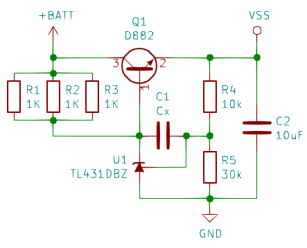
    Modding a module is easier with a circuit diagram. I made one (instead of knitting):

    I'm going to refer to to this diagram when discussing modding options.
  • This linear regulator circuit doesn't look quite right

    Thomas12/25/2019 at 10:55 7 comments

    See Edits below!

    If a product claims have an input voltage range of 4.5V to 40V the internal power supply should be somewhat robust. The DC/DC converter discussed in the previous log entry uses the following as a linear regulator circuit for the 3.6V that I measured with my Fluke voltmeter:

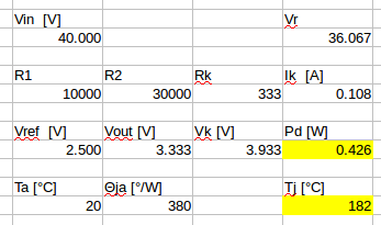
    I used hints from this write-up to do some simple calculations:

    At 40V and a (hypothetical) ambient temperature of 20°C, the TL431 power dissipation is 30% above Absolute Maximum Ratings!
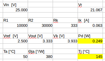
    Since the temperature around the TL431 is bound to be closer to 50°C, an upper limit of 25V would be safer of the TL431 is to stay below the damaging junction temperature of 150°C.
    On the other hand, if I calculate with 25mA operating current of the µC (including LED display) then the LM317 in a TO92 package used in other "DCDC converters w/ voltmeter" impose even lower limits to the supply voltage (19V×0,025A×160°/W + 50°C = 121°C, datasheet).

    This means that the "DCDC-MH" module is a bit more sturdy than the other breeds.

    Of course, this still doesn't explain why I measured 3.6V instead of the 3.33V that the application note makes me expect (maybe the "generic TL431" is rather "D" instead of "B" grade ;-)  ).

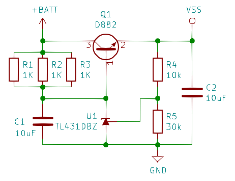
    The other thing that strikes me is the role of Cx. Doesn't amplify noise transmission from +BATT to +VSS?

    The circuit discussed in the write-up mentioned above would be more like this:


    Unfortunately I currently don't know how to simulate the transient response of the linear regulator. Maybe someone has a suggestion?

    Edit 1:

    1. After @Ken Yap pointed out a mistake in my circuit-reading, I corrected calculations and findings. Due to reciprocity of error and effect the results didn't change ;-)

    2. Ken proposed that operation without LED current might be outside the operating range of the linear regulator circuit on the DCDC-MH board, and that it hence reaches 3.6V instead of the expected 3.33V. I tested that hypothesis and didn't find any load dependency:

    • 3.64V without LED
    • 3.64V with LED
    • 3.64V LED + 10mA load
    • 3.63V LED + 30mA load
    • 3.63V LED + 40mA load

    Also I killed the D882 (and had to replace it with an 40 year old BC238 from the used parts box but the voltage didn't change).

    Note to self: there is a reason why the TL431 and 78L05 style linear regulators have protection circuits!

    Edit 2:

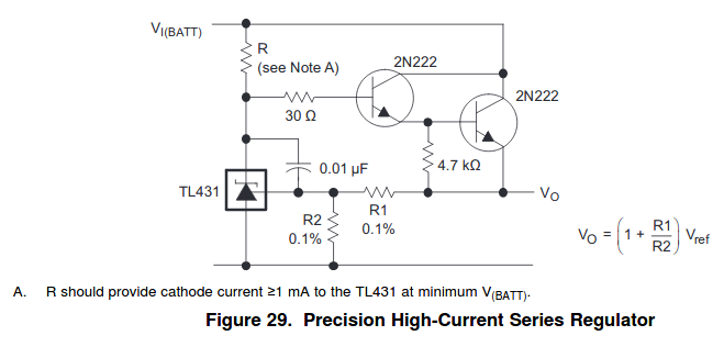
    @rubypanther thinks that the purpose of the cap in the DCDC-MH circuit is soft-start or reduced transient responses. He might have a point, and it might not be unusual at all: the TI TL431 datasheet proposes a very similar circuit:

    Stability and phase reserve of the TL431 seems to be an"interesting" problem for design engineers.
  • The DCDC-MH works (a hack while waiting for Santa)

    Thomas12/24/2019 at 17:29 4 comments

    I tried out my new hot-air rework tool - replacing the µC works great!

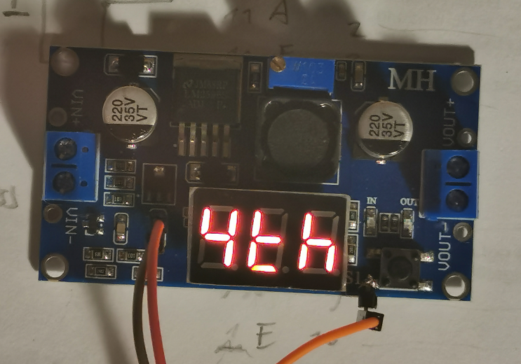
    I then traced a few signals (a first gist is here: https://gist.github.com/TG9541/666e421f80dfbc6cca5957238175bf08) and used the trusty W1209 binary as a starting point.7S-display, LEDs and key "S1" all work, and PD1/SWIM is used for half duplex console.

    Here is the result:


    Edit: gist updated (now including code).
    In case someone wants to order a board: this seller seems to have the lowest price.

  • That's what you'll get today

    Thomas12/24/2019 at 13:08 0 comments

    It's been a while since I ordered two cheap DC/DC converters - today I removed the LED displays to see if it's hackable.

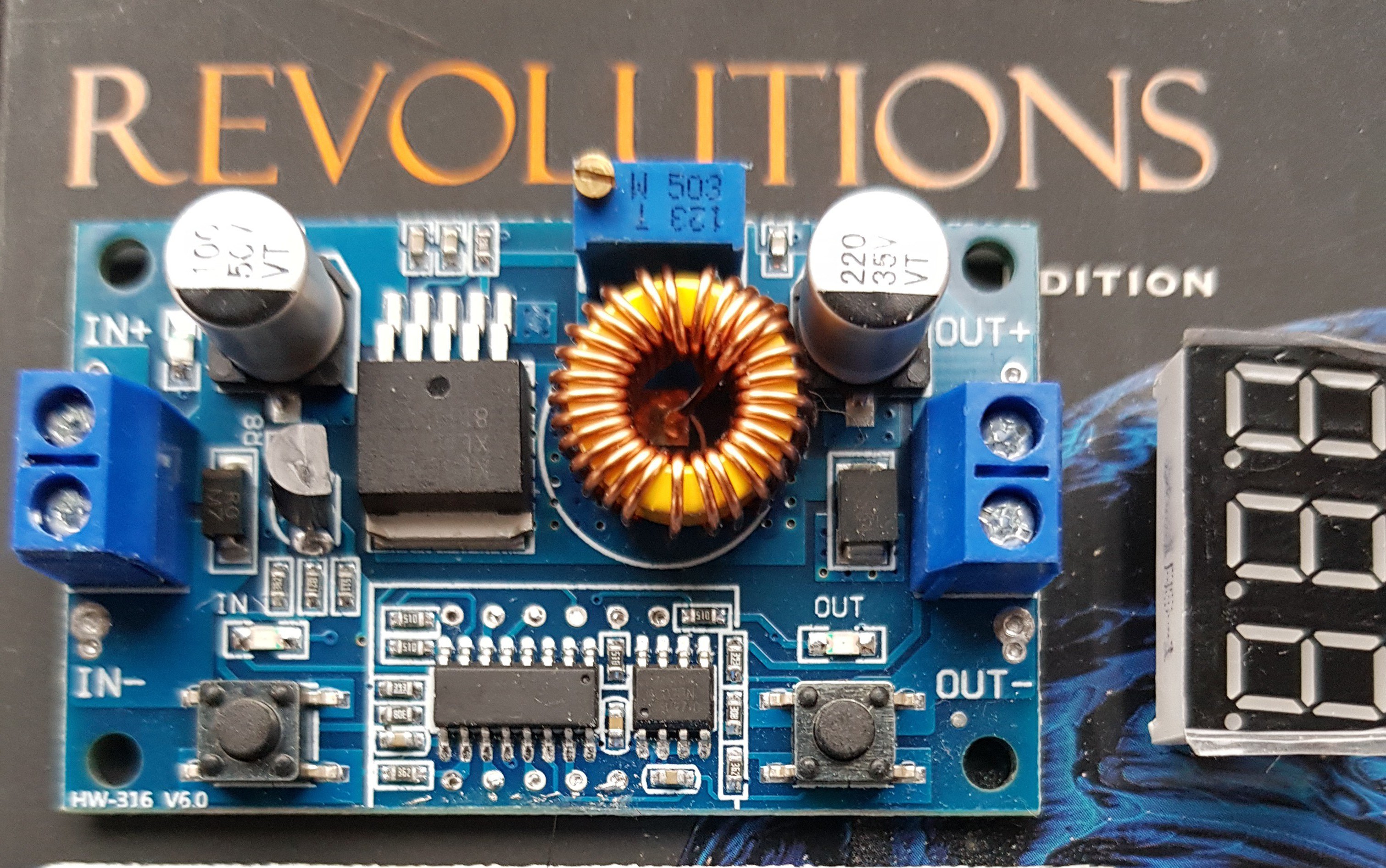
    The second one, the one that looked most promising since the seller's pictures showed ICP pads, turns out to be disappointing:

    First, there are no ICP pads. Second, the voltmeter is controlled by a combination of two chips. The SOIC-8 chip is a 24C02 EEPROM.  I've got no idea why they removed the label from SOIC-16 part, but it's not worth bothering since it's unlikely that a µC without EEPROM would be worth hacking.

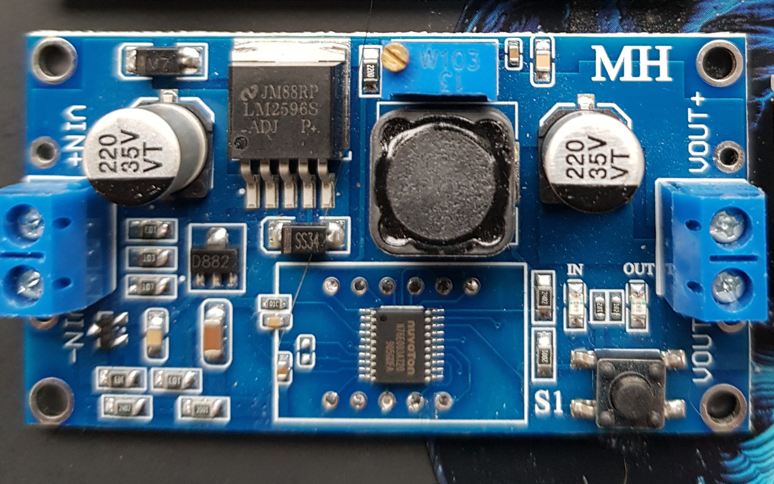
    The second one looks much better: compared to the first specimen the Nuvoton replacement for our trusty hackable STM8S almost looks like a long-lost friend. The guy who made the PCB even was nice enough to keep the option of using an STM8S003F3P6: the unpopulated pads to the left of the µC are for the Vcap capacitor!

    There is more good news: S1 is connected to pin18 - PD1/SWIM. I didn't test it but ut s likey that there is nothing besides the key connected to it. Of course, there is more to figure out before I it's clear that there is still life in hackable DC/DC converters (e.g. a free-ish GPIO with PWM). If someone wants to try it, here is a recent offer for €1.25 / $1.38 (free shipping!)

  • Going Shopping

    Thomas07/27/2019 at 08:48 0 comments

    It's a fact that in the small world of super cheap electronics gadgets the STM8S003F3P6 has been largely superseded by the (more or less) electrically compatible Nuvoton N76E003AT20, an MCS51-style µC.

    Chinese manufacturers are moving on. New designs appear, which are maybe easy to hack, maybe not. Replacing an TSSOP20 µC on a PCB isn't difficult, though, and I decided to give two new very cheap boards a try:

    This one is available for $1.27 (incl. shipping); it clearly has a different circuit design than the ones explored so far in the HaD project. Since mo one west of China knows what's under the LED, I ordered one to figure that out. Maybe it's hackable.

    Another one uses a more modern DC/DC converter silicon, the XL4015, but otherwise it looks very similar to the old design:

    What's promising is the ISP pads on the backside of the board that show a pattern typical for boards with STM8 µC. I don't really expect one there, but who knows. I've seen it for $1.65 (incl. shipping), and maybe I can hack it to run STM8 eForth.

  • Where to go from here?

    Thomas10/22/2018 at 19:06 0 comments

    This project has been very quiet - to be honest about it I don't even know if the $1.50 modules available today still has a trusty STM8S003F3P6 or rather an incompatible (but a couple of cents cheaper) Nuvoton N76E003AT20 under the LED display. It's true, the STM8S003F3P6 chips are getting cheaper again, but as a buyer of "cheap gadgets" you should now be prepared to do some soldering.

    However, STM8 eForth is alive and kicking, and with the code in this project, a $0.85 STM8S103F3P6 breakout board,  and a $0.50 LM2596 module a programmable power supply can be built for ver,y little money. In fact, it's possible to control several LM2596 modules with one Forth module - which should be interesting for robustness tests use cases, like the one described here.

  • STM8 eForth 2.2.22-pre2: Improved Robustness of Serial Interface

    Thomas04/15/2018 at 20:42 0 comments

    Among many other things (e.g. EVALUATE and IDLE Operation) the upcoming STM8 eForth 2.2.22 improves the communication robustness of devices that share the GPIO used for communication with the 7S-LED display.

    The Wiki has also been improved. Check it out!

  • STM8 eForth 2.2.20 tested with the Low-Cost Programmable Power Supply

    Thomas12/23/2017 at 22:51 0 comments

    I just tested one of my green boards with the latest STM8 eForth 2.2.20:

    • the improved e4thcom support works great, even though the communication uses the DP segment
    • #require loads aliases for unlinked words from the folder out/DCDC/target
    • even loading Manfred Mahlow's STM8 eForth VOC extension, which patches the core, works without problems

    The packaging method with automated builds (Travis-CI) used in the W1209 data logging thermostat project works well, and I plan to use it for providing pre-build "programmable power supply" binaries.

  • STM8EF v2.2.15: e4thcom 2-wire mode improves DC/DC usabiliy

    Thomas09/17/2017 at 18:29 0 comments

    The latest STM8EF release v2.2.15 contains a CN2596 DC/DC board binary that works great with the latest e4thcom STM8EF plug-in.

    Here is a demo (asciinema garbled the console key input a bit):

    Please note that the coding examples can now use the e4thcom Forth code #include & #require features. It's also possible to create binaries from the same code using the STM8S simulation feature of uCsim.

View all 30 project logs

  • 1
    Step 1

    Note: the picture in this log entry shows a fully modified board.

    Prepare the board:

    1. remove LED "IN"
    2. remove LED "OUT"
    3. interrupt the connection between LM2596 pin 5 (!ON/OFF) and GND (i.e. cut the pin in the middle, and de-solder the lower half)
    4. carefully cut the copper trace between the LM2596 heat sink GND and the 330R next to the trimmer.
    5. cut the copper trace between LM317 pin2 and anode pad of LED "IN". Expose some of the copper of the trace near said pad.
  • 2
    Step 2

    Add new components:

    1. solder a C 100nF between LM317 pin 2 and GND on the backside of the PCB
    2. solder a 10µF ceramics capacitor 0603 or 0805 over the now cut copper trace between the LM2596 heat sink GND and the adjacent pad of the 330R next to the trimmer
    3. solder a 47R 0805 resistor to the pads of LED "IN"
    4. solder a 1k8 0805 resistor to the pads of LED "OUT"
  • 3
    Step 3

    Make new connections for controlling the LM2596:

    1. add a wire between the cathode pad of LED "OUT" (PB4) and LM2596 pin 5
    2. add a wire between the copper trace near the anode pad of LED "IN" (PC3) to the 330R pad, where also the 10µF capacitor is connected
    3. connect (pin 2 || pin 3) of the trimmer to pin 1 of the voltage adjust trimmer on the board

View all 6 instructions

Enjoy this project?

Share

Discussions

Ken Yap wrote 12/30/2019 at 22:06 point

If you regard the TL431 as an amplifier then the capacitor reduces the gain as the frequency increases so I think you're right in your guess that it's to dampen higher frequency response.

  Are you sure? yes | no

rubypanther wrote 12/25/2019 at 19:10 point

Is it possible that Cx is for soft start?

  Are you sure? yes | no

Thomas wrote 12/25/2019 at 19:22 point

That's quite possible but it would also limit the transient response, wouldn't it? It's not always easy to get an idea of the dynamic behaviour of black-boxes like the TL431, but it looks like Cx makes accidentally creating a short-wave transmitter less likely. Maybe I should unsolder it and test its capacitance value. 

  Are you sure? yes | no

rubypanther wrote 12/25/2019 at 19:44 point

The datasheet has a similar capacitor in a flasher circuit in the applications, so I think it would definitely reduce the transient response.

  Are you sure? yes | no

Thomas wrote 12/25/2019 at 19:52 point

Are you're referring to the flasher circuit in the TI LM317L-N datasheet? Isn't the point of the caps there to make the circuit oscillate (flash)?
You may be right anyhow: there is an example with a "middle cap" in the TI TL431 / TL432 datasheet.

See Fig29 in https://www.ti.com/lit/ds/symlink/tl431.pdf

  Are you sure? yes | no

rubypanther wrote 12/30/2019 at 20:10 point

Yeah, sorry for the slow reply, I figured oscillation is the extreme case of reducing the response, or rather if you reduce multiple times with different values you might go in a circle.

I'm sure there are cleaner ways of thinking about circuits! LOL I have a software background, so I usually think algorithmically. In this case I was mostly just looking at the pictures, and I thought something like, 1/3rd of an oscillation is a DC pulse.

  Are you sure? yes | no

Thomas wrote 12/30/2019 at 21:46 point

@rubypanther  that's no problem - if things involve feedback and phase shift figuring out what's likely to happen is tricky. Such a thing once "won" me a trip to Sweden (as in "we demand that a representative comes here on the **next** plane!") - it was a TL431 stability issue, and the electronics design engineer was a very experienced guy ;-). By the way, it should be possible to model the circuit with some lines of Python or C++. Maybe I'll give it a try.

  Are you sure? yes | no

hobby16 wrote 03/16/2018 at 16:11 point

Great  hack, thank you!

I've ordered a couple of this board and begun modding the hardware.

But I stopped short at that sentence : "connect (pin 2 || pin 3) of the trimmer to pin 1 of the voltage adjust trimmer on the board"

I wrapped around my head trying to understand but I can not make any sense out of it. If I connect the trimmer's pin 2 or pin 3  to pin 1, it means shorting the trimmer so the board's output is directly connected to the LM2596 feedback input! It can NOT work.

Can you please clarify the sentence or rephrase it? If it means as what I understood,  I don't see how can anyone has possibly managed to make the board work. Note that I don't doubt one second that injecting an offset to the fbk pin is the way to have a micro-controller controlled switch mode power supply, it's what's is done in any Chinese modules I've seen.

Thank you in advance.

  Are you sure? yes | no

Thomas wrote 03/16/2018 at 21:02 point

Hi, you're right, that's obviously gibberish, most likely a rest of an earlier text I forgot to remove  :-)

The trimmer remains unchanged, and as you rightly guessed, an offset is injected at the former GND side of the feedback voltage divider.

  Are you sure? yes | no

hobby16 wrote 03/16/2018 at 23:11 point

Thank you for confirming, Thomas!

I have removed the trimmer anyway and replaced it with a 4.7k  SMD 0805 resistor soldered between trimmer's pin 2 & 3 to avoid any change to my calibrations. On the other module, I'll keep the trimmer, set it at mid-position and block its screw with glue.

  Are you sure? yes | no

Thomas wrote 03/17/2018 at 10:24 point

Success with hacking the DC/DC converters! Feedback, and hints for improvements, are highly appreciated! It would also be great if you shared pictures of you modified boards!

  Are you sure? yes | no

richard wrote 09/18/2017 at 04:01 point

I've ordered a couple of these to play with. I'll be using a nominal 24 volt supply so If I set the output voltage to 20V when PWM=0 I'm hoping this gives me a 0-20V adjustable supply.

  Are you sure? yes | no

Thomas wrote 09/18/2017 at 05:05 point

This will most likely work. Expect, however, reduced control performance, especially from the lower 25% on. Performance will most likely leave a lot to wish for below 1V (but you can disable the converter, and for static loads you can create an "outer control loop" using the ADC). The LM2596 datasheet recommends selecting the inductor depending on the design power, and the required voltage transformation (-> discontinuous mode -> higher noise). Noise can be reduced by adding a inductor/capacitor network at the output.
https://www.onsemi.com/pub/Collateral/LM2596-D.PDF

  Are you sure? yes | no

richard wrote 09/18/2017 at 06:58 point

I don't have lab quality expectations. After all, there is only so much you're terrific Forth implementation can do to overcome the dodgy $2 hardware.

I was weighing up using the W1209 and an external DAC driving a linear regulator. But I had so many choices in the junk box that I was spinning my wheels. I still might explore that option but I think the LM2596 will suffice.

  Are you sure? yes | no

Thomas wrote 09/18/2017 at 19:02 point

OK, for automated robustness tests (e.g. automotive, machine control, etc) even a dodgy hardware is good (one might argue "if the circuit still works with that much noise it already passes the first test").
Considering the price, the LM2596 is OK. Efficiency-wise the XL4005 is maybe a better choice (but the control offset is just 0.8V, which requires a lower PWM duty cycle than what's needed for the 1.2V of the LM2596). If no 7S-LED display is needed a single STM8S003F3 can control up to 6 DC/DC converters.

  Are you sure? yes | no

Elliot Williams wrote 04/10/2017 at 19:10 point

I love the idea of a simple/cheap programmable power supply as a demo project for your Fortheries, so I ordered two of these things a few weeks ago.  As luck would have it, I got the "first variant" versions of the boards (or maybe something else, who knows?).  

To anyone following along: the big difference in board appearance is that the "first variant" board has more discrete components visible -- three resistors next to the TO92 package and two on either side of the display.  Don't get that board if you want to retain the display.

So I popped the display off and soldered some wires on.  Of the SWIM and UART lines, the only one that's not broken out into a through-hole is the NRST, which you may not need.  I gently lifted the pin and fly-wired it anyway. 

On my board, the chip needed unlocking, so I ran stm8flash with the -u flag first, and then uploaded a version of Thomas' stm8ef that didn't need to use the half-duplex hack, because without the LED you have clear access to both the TX and RX lines.  

So far, so easy.  Next I'm going to hack on Thomas' control routines for the  LM25596.  I'm half tempted to see if some minor code changes can turn this into a solar-cell MPPT device.  We'll see.

  Are you sure? yes | no

Thomas wrote 04/11/2017 at 05:36 point

Hi Elliot, the MPPT idea sounds great!

If you want to continue with the "first DC/DC PCB type", most of what I know about it is described in the log entries below. I also have half-baked code to control the LED display. If necessary I can refactor it to meet the improved "board framework" conventions but as you live in Germany I can also send you one of my a "green" DC/DC boards by mail.

If no LED display is required, an MPPT might also be feasible using plain DC/DC boards, and a STM8S breakout board. So far I didn't find out whether measuring the current is necessary for an optimal MPPT.

Here are log entries on the first DC/DC board variants:
https://hackaday.io/project/16097-eforth-for-cheap-stm8s-gadgets/log/51072-a-dcdc-converter-with-a-voltmeter

https://hackaday.io/project/16097-eforth-for-cheap-stm8s-gadgets/log/51120-more-details-on-lm2596-with-voltmeter

Here is a bit on getting a PWM out of TIM1:
https://hackaday.io/project/19647-low-cost-programmable-power-supply/log/52861-some-progress-and-a-refresh-of-a-lesson-learned

  Are you sure? yes | no

Elliot Williams wrote 04/11/2017 at 08:26 point

Thanks!  I was looking through those links late last night.  And no need to send me a green one -- ebay is already on the case. My impatience costs me only 2€.

Summarizing the voltage control routine to see if I've got it right: you inject an offset voltage into the voltage divider between the output and feedback pins by disconnecting a resistor to ground and replacing ground with a filtered-PWM voltage.  

You then look the PWM up in a table?  Why not close the loop on output and vary the PWM until it produces the desired output?  Is it unstable?  Have you tried?  Some combo of the lookup table PWM plus fine-adjustment should get the voltage "accurate" down to the resolution of the ADC.  (Of course, no voltage reference, etc.)

For MPPT: yeah, current is also necessary. But without the LED, I've got a lot of free pins. :)    

  Are you sure? yes | no

Thomas wrote 04/11/2017 at 17:05 point

You're of course right in all points:
* injecting an offset lowers the output voltage, but it also reduces the DC/DC control loop gain by a factor of (1-offset/1.25V)

* the lookup table acts as a open-loop-control component for the DC/DC converter's closed-loop-control set-point, and it greatly improves stability and responsiveness of this hack. However, a feedback component can help to reduce the residual control error. I guess that a PID controller would be a good addition, even though the voltmeter resolution is just about 50mV. Also, the lookup-table can be "self-learning".

* Removing the LED-display from any variant of the DC/DC converter turns the display's solder pads into a STM8S003F3 breakout. Who needs a display if the power supply is networked and automated, and the visualization (if needed) can be done with a central "dashboard"? Really a smart idea!

EDIT: the Wiki page on the CN2596 board now contains some info on STM8S003F3 and LED display connections: https://github.com/TG9541/stm8ef/wiki/Board-CN2596#cn2596-circuit-info

  Are you sure? yes | no

K.C. Lee wrote 02/04/2017 at 12:24 point

>it was necessary to solder patch wires to pins of a 0.5mm TSSOP package.\

It is actually 0.65mm pitch.

  Are you sure? yes | no

Thomas wrote 02/04/2017 at 13:34 point

Thanks! Fixed.

  Are you sure? yes | no

Similar Projects

Does this project spark your interest?

Become a member to follow this project and never miss any updates