Close
0%
0%

Steam Controller Capacitive Bumper Mod

I find the bumpers on the Valve Steam Controller to be difficult to push,
so let's replace them with touch sensors!

Public Chat
Similar projects worth following
119 views
Whether or not you consider Valve's Steam Controller to be the most versatile gamepad available, most agree that the shoulder buttons are one of the weak points in the design. They're loud, they require a much heavier activation force than alternative controllers, and they
rely on a plastic leaf spring which has been known to snap over time. Playing a bumper-mashing game like Dark Souls or Rocket League can risk breakage, and I've been adjusting my usage to relegate the bumpers to secondary, rarely-used functions.

I wanted to modify the steam controller to improve the bumpers while meeting some criteria:

* Improve bumper feel.
* Lower activation force.
* Eliminate risks of breakage.
* Mod should be fully removable.
* No dremeling the case.

Steam Controller Capacitive Bumper Mod

I find the bumpers on the Valve Steam Controller to be difficult to push, so let's replace them with touch sensors!

Whether or not you consider Valve's Steam Controller to be the most versatile gamepad available, most agree that the shoulder buttons are one of the weak points in the design. They're loud, they require a much heavier activation force than alternative controllers, and they rely on a plastic leaf spring which has been known to snap over time. Playing a bumper-mashing game like Dark Souls or Rocket League can risk breakage, and I've been adjusting my usage to relegate the bumpers to secondary, rarely-used functions.

I wanted to modify the steam controller to improve the bumpers while meeting some criteria:

  • Improve bumper feel.
  • Lower activation force.
  • Eliminate risks of breakage.
  • Mod should be fully removable.
  • No dremeling the case.

Some users have modded alternative mechanical keyswitches onto the controller itself, this redditor achieves their goals with dremel and direct wiring [MechKeyboardMod]. While I wouldn't want to make a permanent change to the case, I could instead 3d print parts of the case to allow physical modification without damaging the original parts. Valve provides CAD files for all parts on the controller [ValveCAD]. I was eventually inspired by another hackaday project [TouchButtonMouse] to use capacitive touch sensors instead of mechanical switches. Look at these tiny little `ttp223` sensor boards:
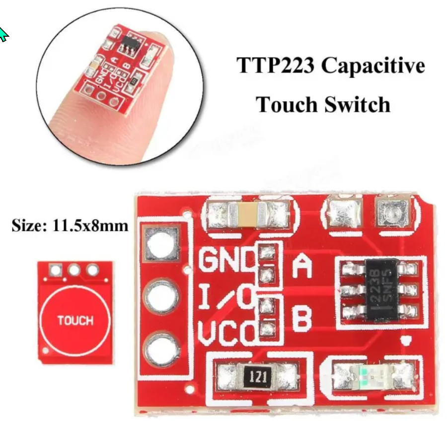

ttp223 imagery. (amazon.com)


  • 1
    Researching the PCB

    In order to mod the PCB, I'll need to figure out:

    • How the bumper's switches are attached to the board.
    • The voltage on the board.
    • Easy places to locate ground and input voltage, since the capacitive sensor will need power.
    • Find a place to physically fit these cute little sensor boards.

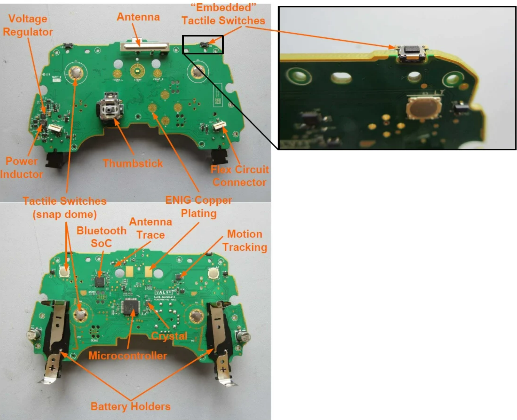
    Since opening up the controller means I wouldn't be able to use it while playing games, I instead sought out the obligatory [iFixit] article on the Steam Controller. It has the high-resolution photography necessary to follow traces and see how the controls are wired up. Combined with another teardown [teardownTuesday], I had quality images and identification of the microcontroller and major components (including the troublesome shoulder bumper microswitches):

    Steam controller PCB overview. (allaboutcircuits.com)

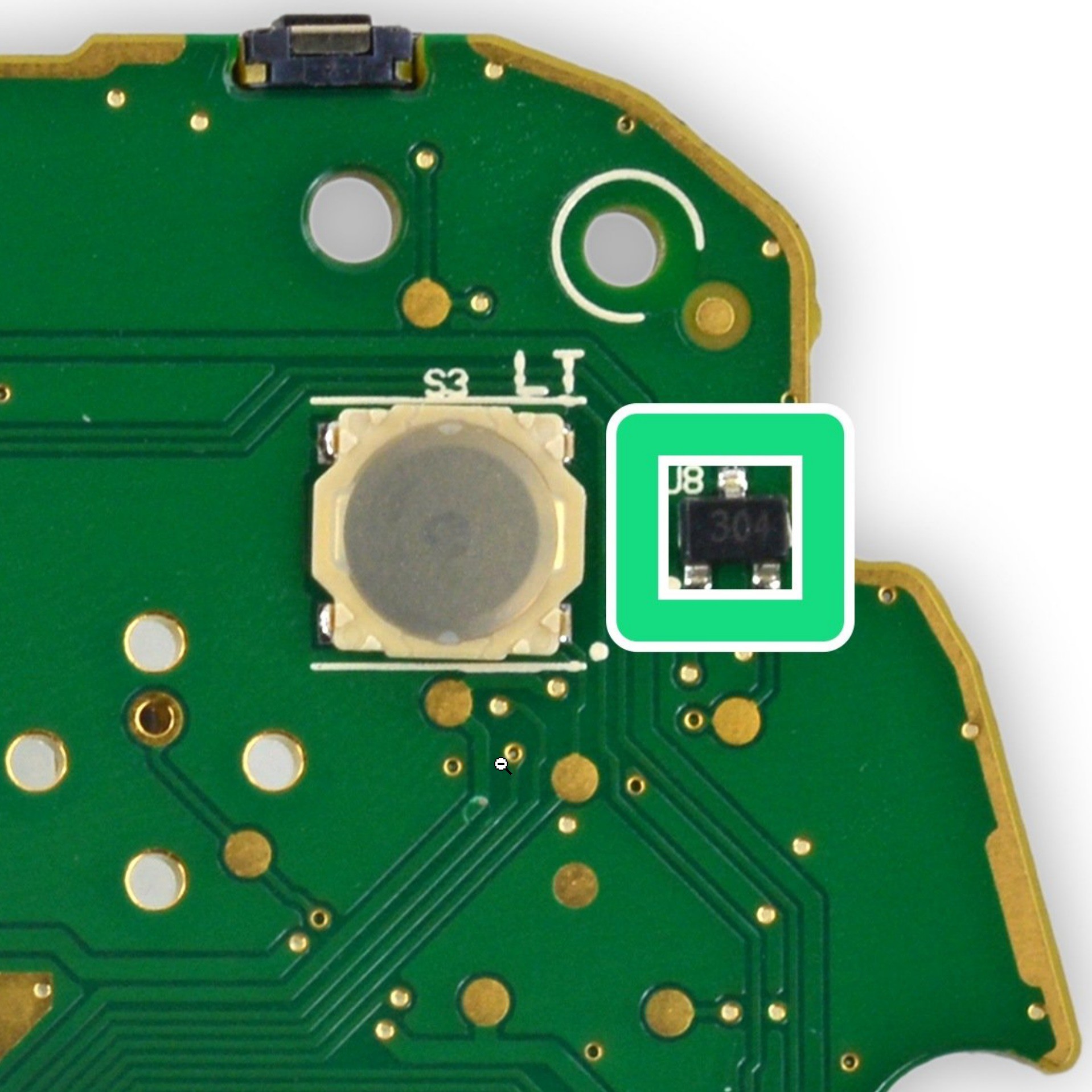
    At this point, I'm pretty confident that the steam controller runs at 3.3v, since it operates on AA batteries. The main PCB has convenient testing points on every major trace, many of the pins for the different components and every physical switch as well. I shouldn't need to scrape away any of the silkscreen to solder onto them:

    Look at all those convenient pads. (ifixit.com)

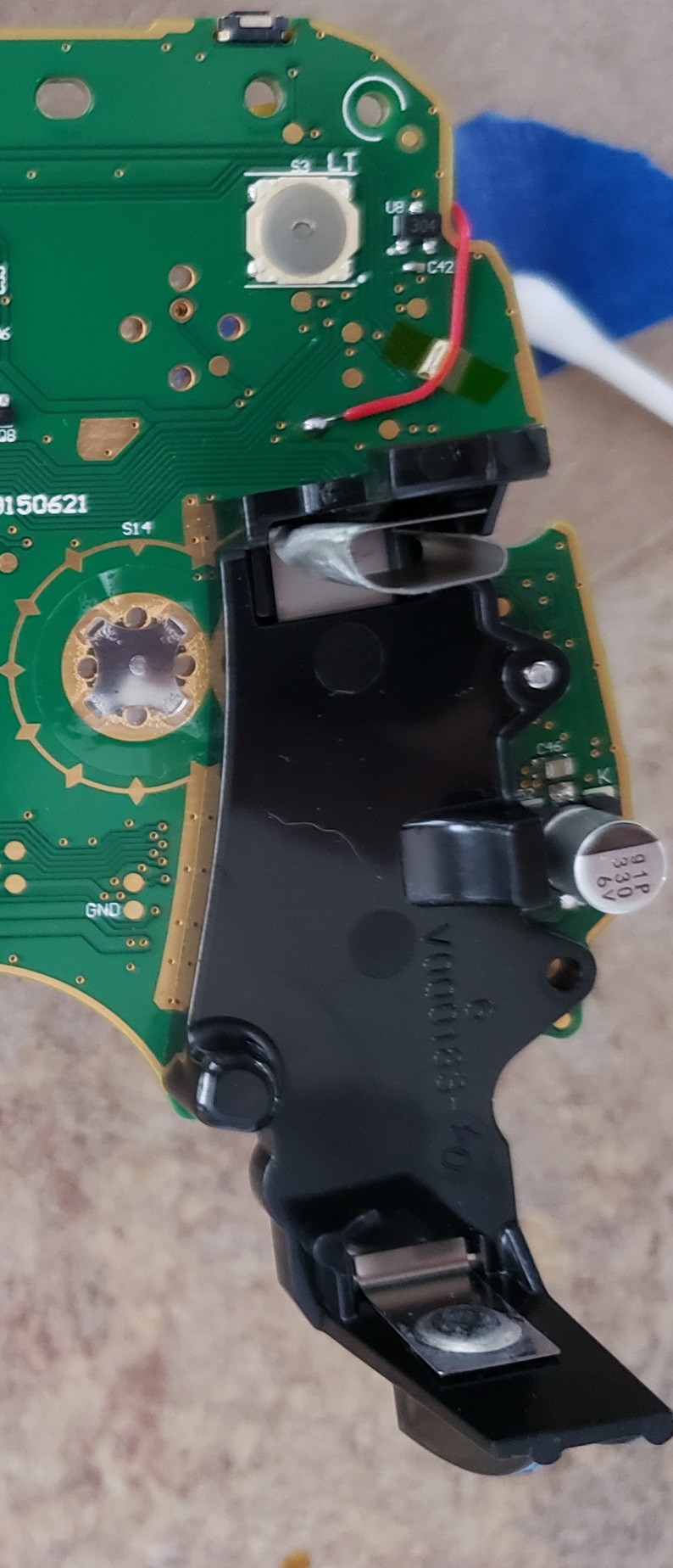
    It took some time to figure out an easy spot to get at input voltage. In particular, I didn't want to get it directly from the batteries since I'd rather not have the touch sensors pulling power when the controller was "off". I'm a member of the Steam Controller Discord Community, and a Valve developer pointed out that there are unpopulated components and most of them are on the power trace. I also used the datasheet of the Arm Microcontroller: NXP LPC11U37F, to determine the power pins. I visually traced back and found the power pins all connected to this extra-wide trace. This trace passes very near the left side trigger and bumper.

    Here's the test point I soldered onto for power.

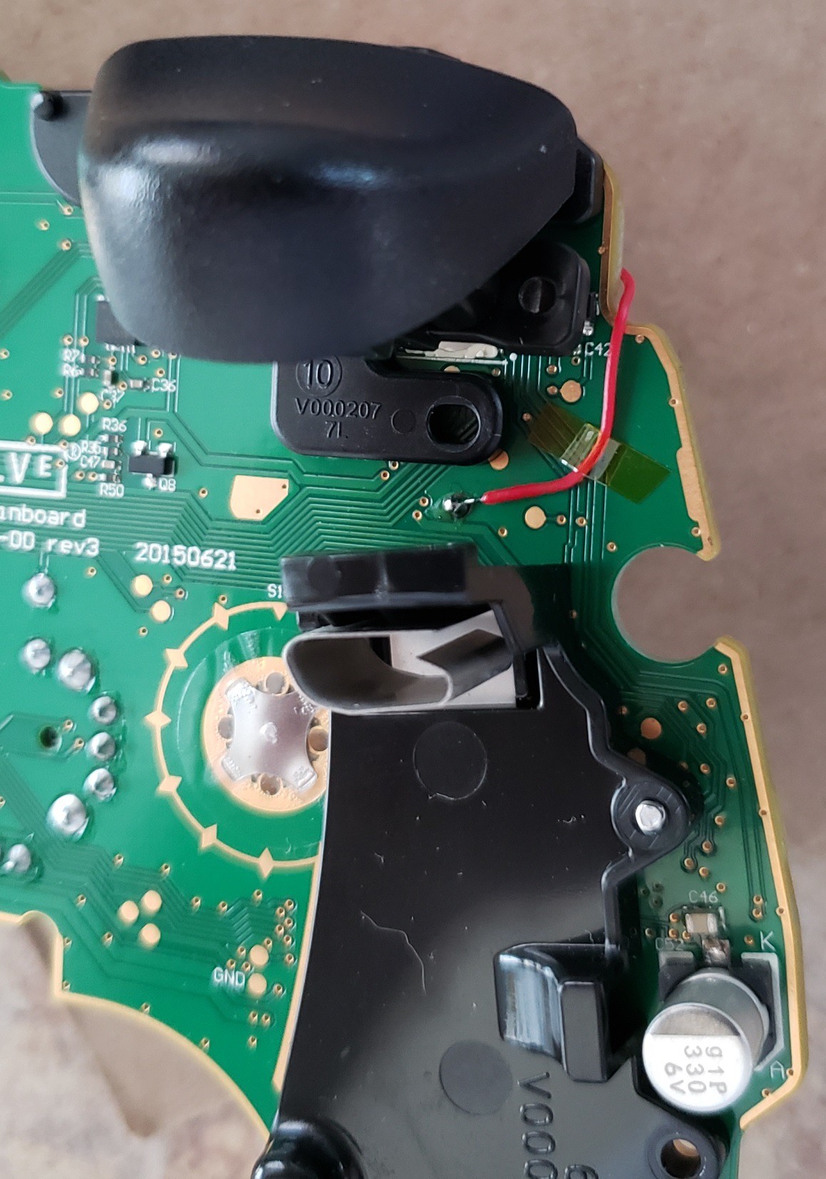
    The big complication in using the test points on the PCB is that some of them sit underneath plastic parts which are screwed tight to the  board. The bumper input traces are both underneath the trigger  assembly's plastic mechanism. Luckily the bumper switches themselves are soldered onto a trace which is free of plastic. I also determined at this point that all the buttons are connected to ground, and I'll have to configure the touch sensor in active-low mode.

    Notice how the plastic is covering up the bumper's test pad.

  • 2
    Breadboard Prototype

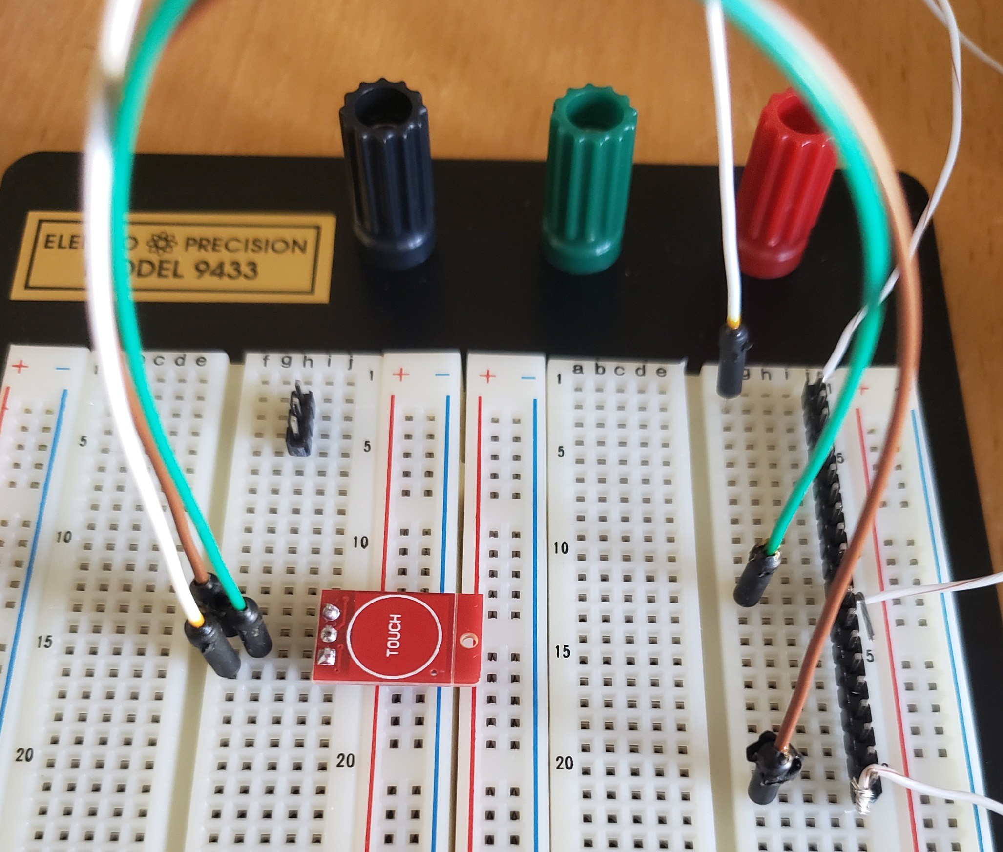
    Now to put something together on the breadboard. I connected jumper A, which changes the `ttp223` to active-low instead of active-high. This means the LED will be on by default, and will turn off when the touch sensor is triggered. Then soldered on some pins so that I could set the `ttp223` on the breadboard.

    Minimum viable product.

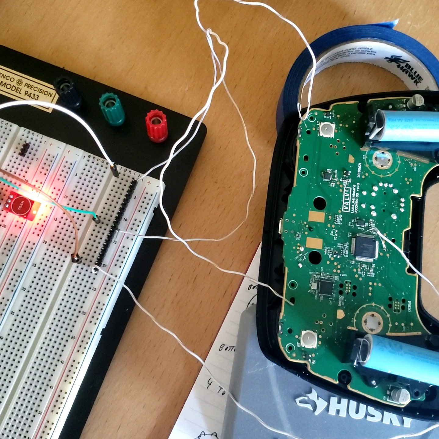
    I attached some scrap wire to each of the 3 pins on the `ttp223` and connected those by hand to the bumper input testing pad, ground, and one of the input voltage pins on the microcontroller. Then I added batteries to the controller and confirmed:

    • The `ttp223` module led turns on and off with the controller.
    • The `ttp223` module, when touched, causes the controller software to register that the desired bumper button is pressed properly.

    It's alive!

    An unfortunate discovery: Even though the datasheet states otherwise, these `ttp223` modules cannot maintain an active touch for more than 15 seconds. I purchased similar modules from another supplier and the timing was even worse; only maintaining 5 seconds of active touch before the circuit reset. I wonder if these are counterfeits which don't meet specification, or maybe the extra components are affecting the touch sensor. I'll have to put up with the shortcoming. Perhaps in a future iteration, I can purchase some modules which perform to spec.

  • 3
    Version 1

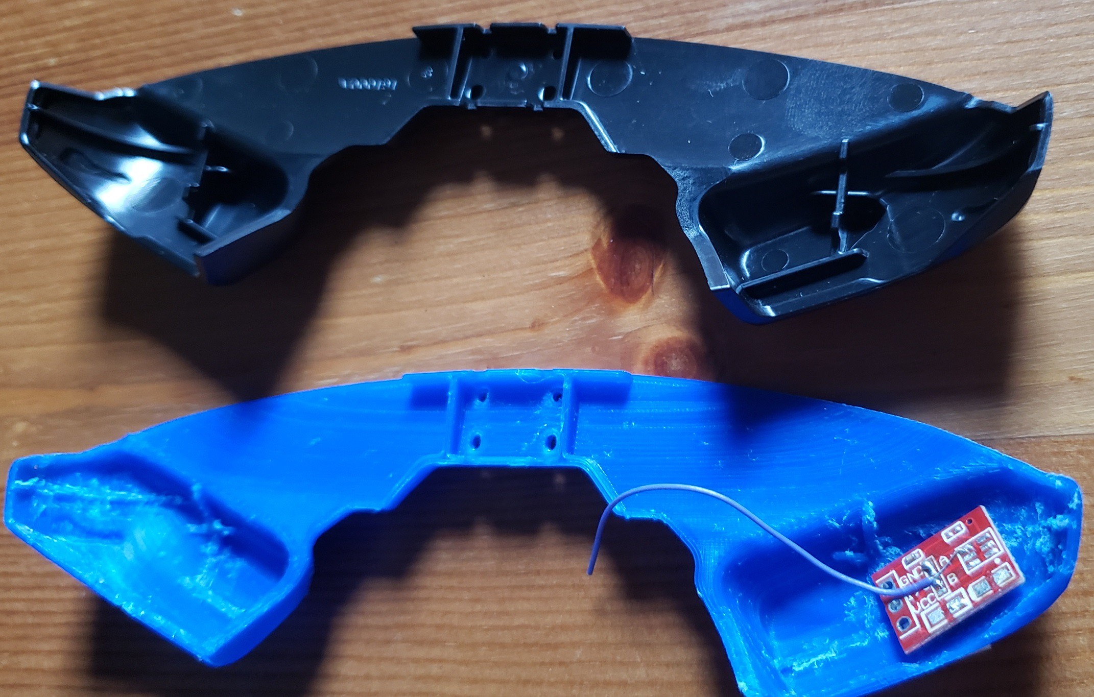
    At this point, I'm confident that the `ttp223` module itself can fit entirely inside of the original plastic button for the Steam Controller's bumpers with ample room to spare. However, there's some framing inside the original bumper plastic which will get in the way. To avoid damaging the original plastic parts, I will 3d-print a new bumper. Someone's already done most of the legwork necessary by converting the full CAD files into a more printer-friendly set of `stl` files [steamControllerSTL]. The original parts are meant for injection-molding, they're very thin and curved. It took some trial-and-error to select an orientation that didn't waste too much material on supports while also not warping. I recommend you print the part with the buttons facing downwards. You'll end up having to do a fair bit of sanding to the button surfaces this way, but it's much easier than cleaning the supports out of the button cavity itself.

    Speaking of the button cavity, I took a dremel to the plastic framing inside the button cavity itself. The framing functions to strengthen the thin plastic, and to focus the force of the button press onto the microswitch. I don't want that microswitch to be touched, and don't intend to actually press these buttons at all, so I removed all of it with a dremel. Note: I'm printing in basic PLA because I'm a total novice at 3D-prints, and my library allows me to submit jobs inexpensively.


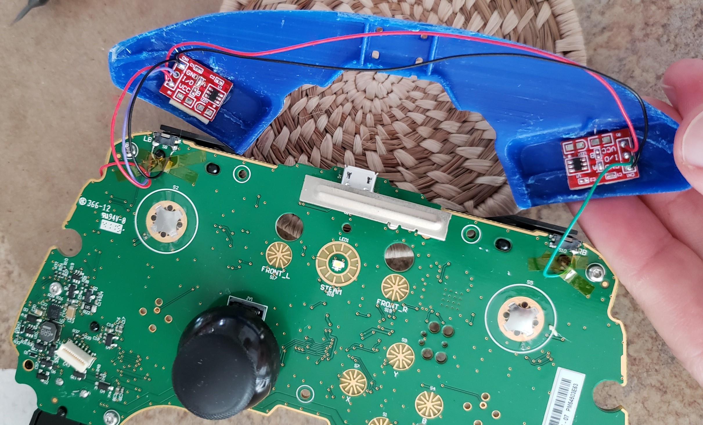
    Bumper replacement in blue, all sanded and dremeled.

    At this point, I've also tried attaching the `ttp223` boards to the PLA print with a couple methods, determing that hotglue holds best. Now I discover that the touch surface is so sensitive that it can read my finger through the 3D-printed plastic. This is a bonus as it means I can just glue the boards to the backside of the bumper buttons and not have to resort to using metal lugs or screws to carry capacitance from my finger to the `ttp223` input pin.

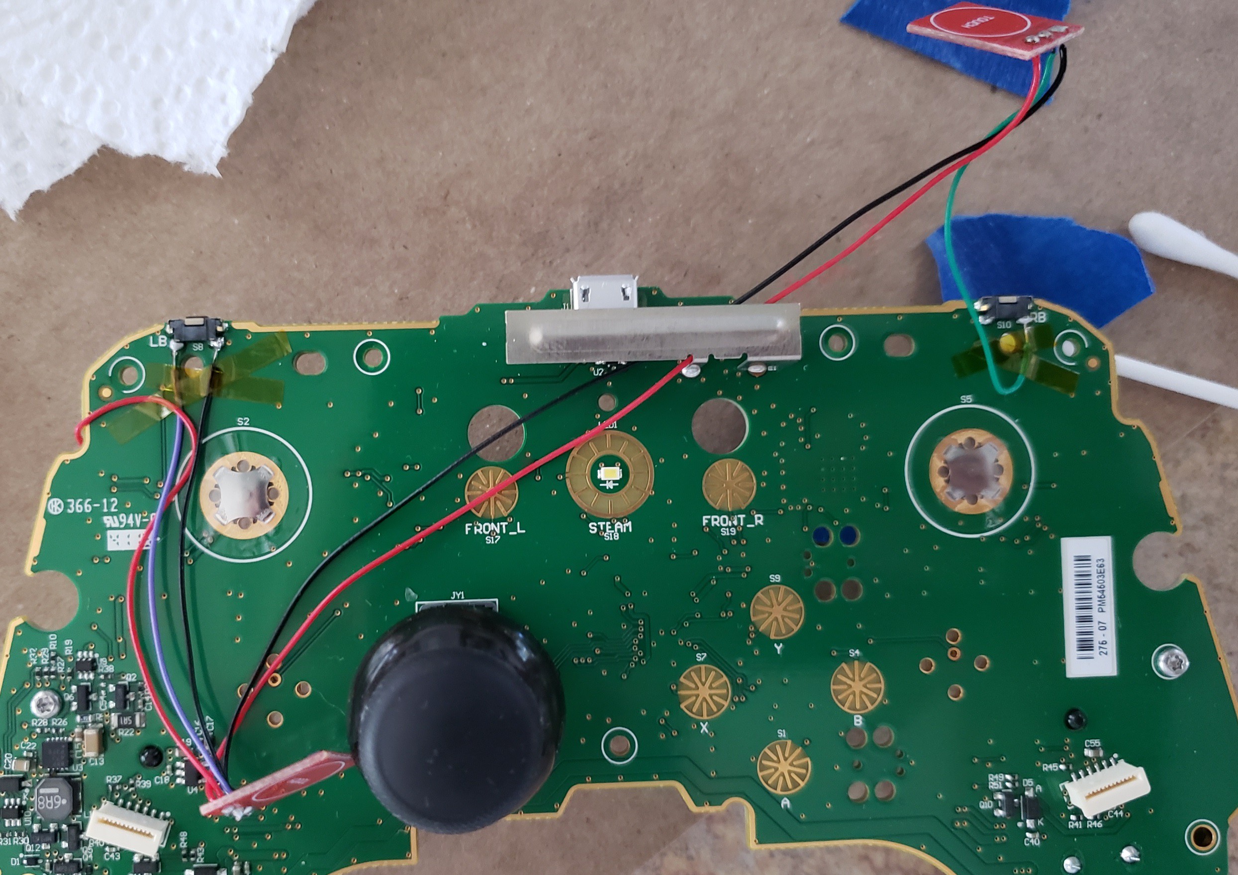
    Time to prepare some of the `ttp223` modules for use inside the controller. I desoldered the LEDs since I won't see it and perhaps reduce the power draw on the batteries. I also soldered jumper A on both modules. Then I started soldering to the steam controller PCB:

    1. I connected to input voltage from the test point noted in the earlier section (red wire; there's a few pictures up the page a bit). That wire had to wrap around to the backside of the PCB.
    2. I connected to ground using one of the pads meant for the microswitch (black wire).
    3. I connected each module's input to the active pin on each of the microswitches (green and purple).
    4. I'm chaining ground and input voltage between the two modules to bridge the gap between the two bumper buttons.


    Yes it's entirely too much solder.

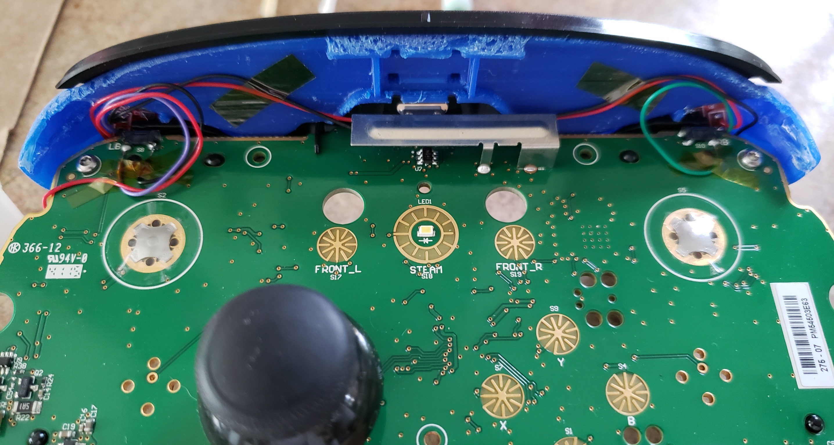
    Next, I glued the touch sensors into place inside the 3D-printed bumper. I powered on the controller to confirm everything was wired up properly, and finally time to reassemble.


    Sensor modules glued into place


    Reassembling the controller.

View all 6 instructions

Enjoy this project?

Share

Discussions

Similar Projects

Does this project spark your interest?

Become a member to follow this project and never miss any updates