 goathens
-
1Researching the PCB
In order to mod the PCB, I'll need to figure out:
- How the bumper's switches are attached to the board.
- The voltage on the board.
- Easy places to locate ground and input voltage, since the capacitive sensor will need power.
- Find a place to physically fit these cute little sensor boards.
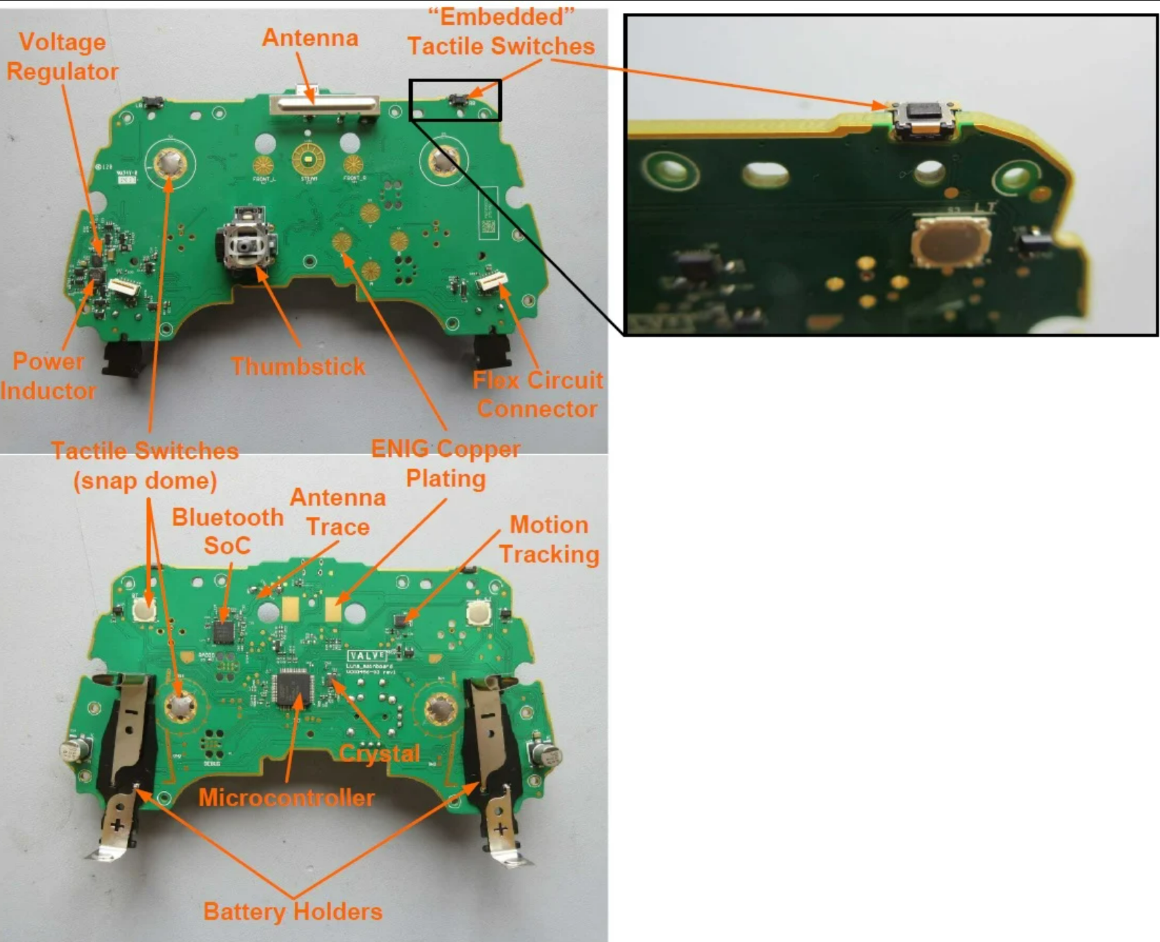
Since opening up the controller means I wouldn't be able to use it while playing games, I instead sought out the obligatory [iFixit] article on the Steam Controller. It has the high-resolution photography necessary to follow traces and see how the controls are wired up. Combined with another teardown [teardownTuesday], I had quality images and identification of the microcontroller and major components (including the troublesome shoulder bumper microswitches):
![]()
Steam controller PCB overview. (allaboutcircuits.com)
At this point, I'm pretty confident that the steam controller runs at 3.3v, since it operates on AA batteries. The main PCB has convenient testing points on every major trace, many of the pins for the different components and every physical switch as well. I shouldn't need to scrape away any of the silkscreen to solder onto them:
![]()
Look at all those convenient pads. (ifixit.com)
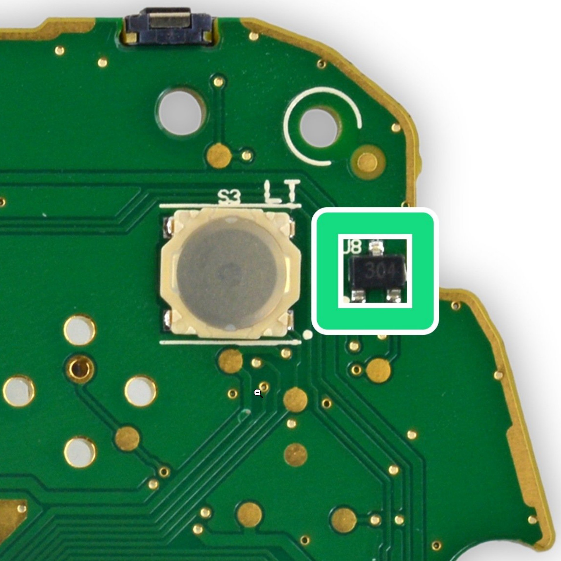
It took some time to figure out an easy spot to get at input voltage. In particular, I didn't want to get it directly from the batteries since I'd rather not have the touch sensors pulling power when the controller was "off". I'm a member of the Steam Controller Discord Community, and a Valve developer pointed out that there are unpopulated components and most of them are on the power trace. I also used the datasheet of the Arm Microcontroller: NXP LPC11U37F, to determine the power pins. I visually traced back and found the power pins all connected to this extra-wide trace. This trace passes very near the left side trigger and bumper.
![]()
Here's the test point I soldered onto for power.
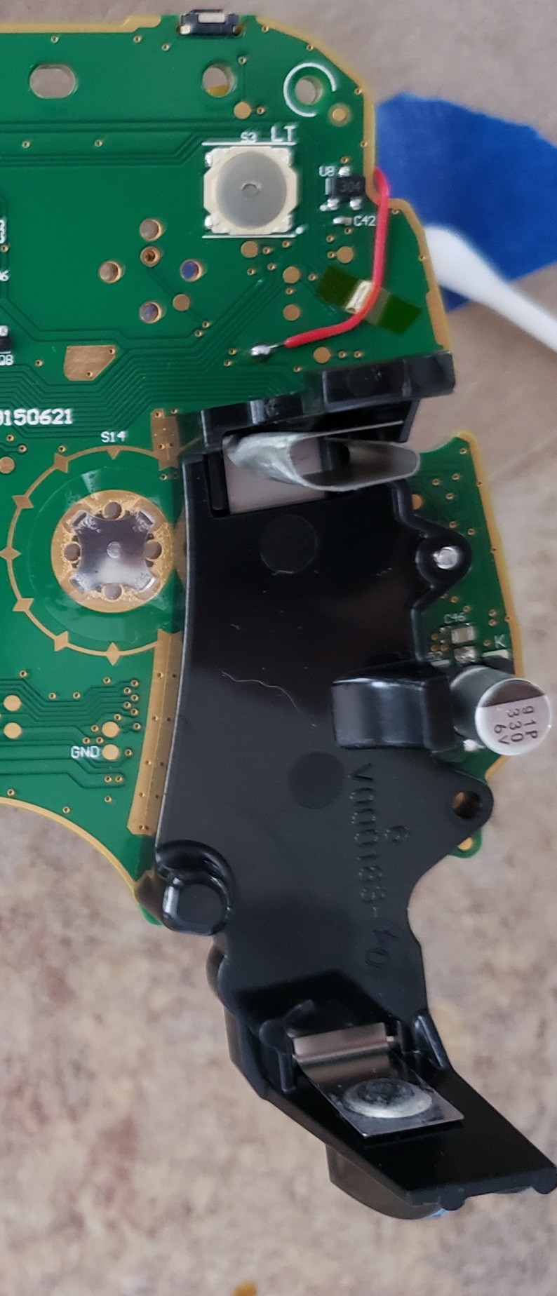
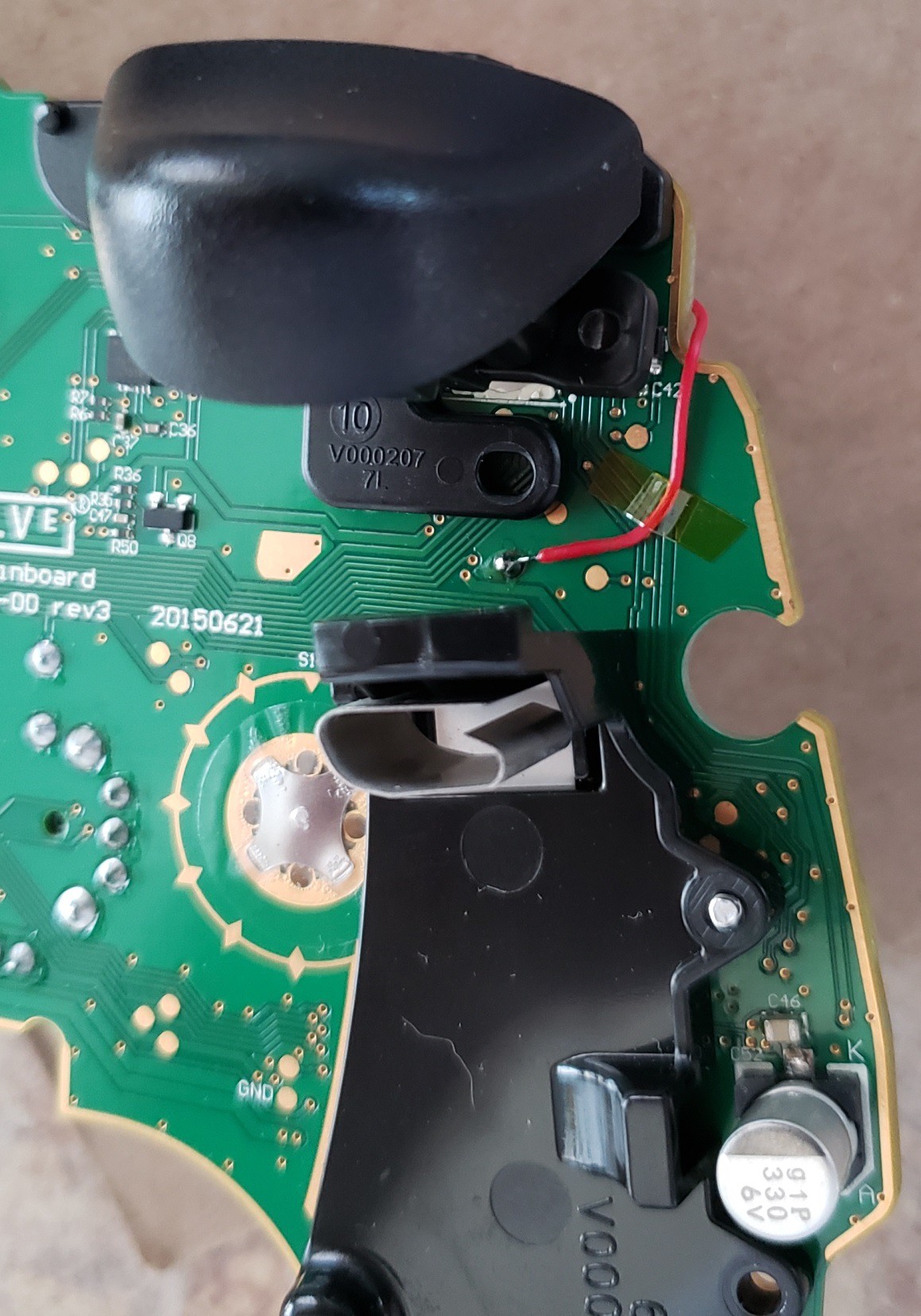
The big complication in using the test points on the PCB is that some of them sit underneath plastic parts which are screwed tight to the board. The bumper input traces are both underneath the trigger assembly's plastic mechanism. Luckily the bumper switches themselves are soldered onto a trace which is free of plastic. I also determined at this point that all the buttons are connected to ground, and I'll have to configure the touch sensor in active-low mode.
![]()
Notice how the plastic is covering up the bumper's test pad.
-
2Breadboard Prototype
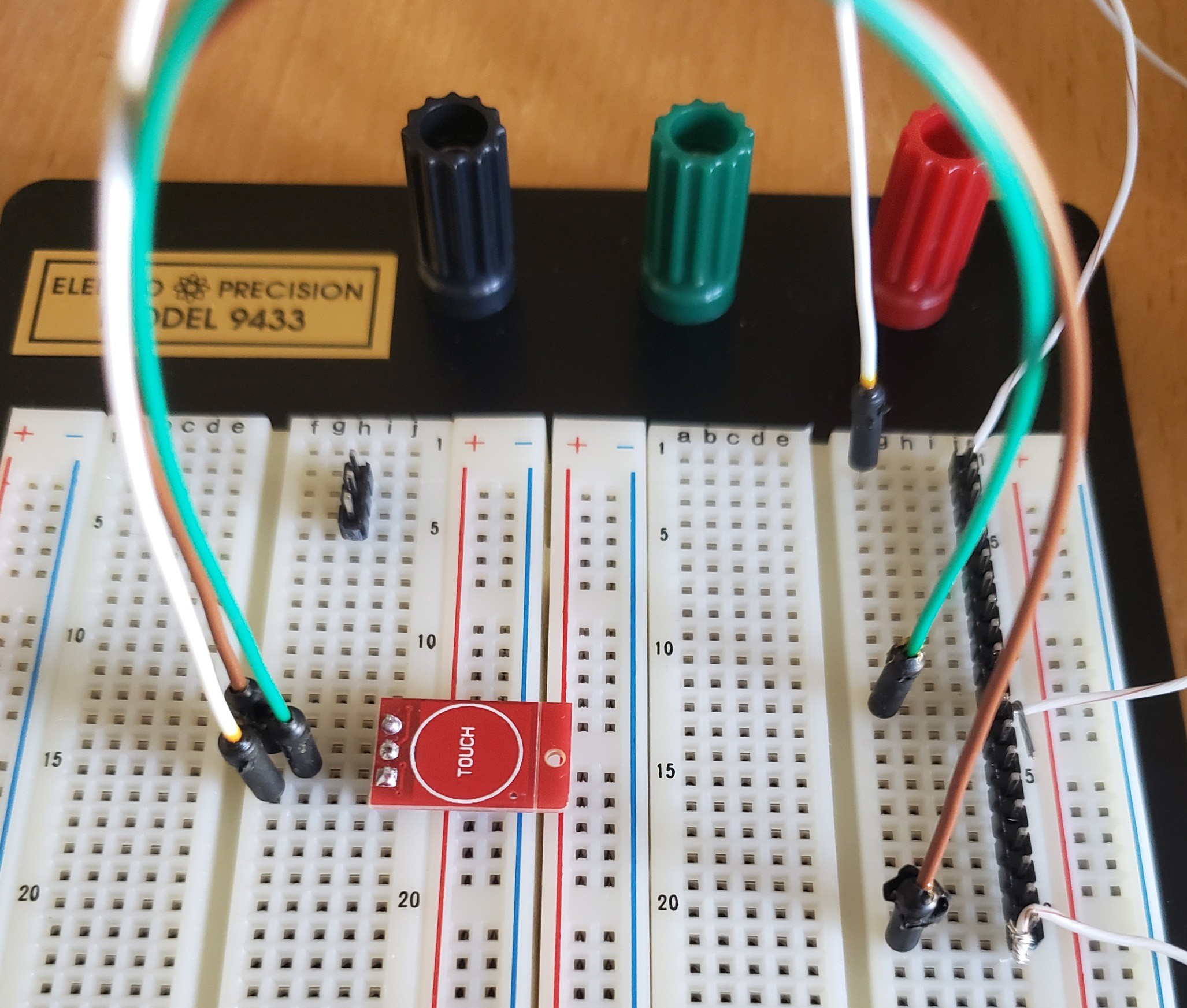
Now to put something together on the breadboard. I connected jumper A, which changes the `ttp223` to active-low instead of active-high. This means the LED will be on by default, and will turn off when the touch sensor is triggered. Then soldered on some pins so that I could set the `ttp223` on the breadboard.
![]()
Minimum viable product.
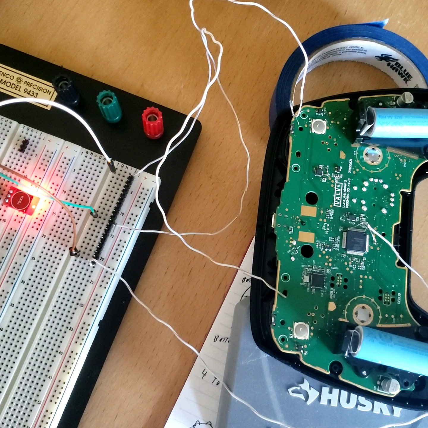
I attached some scrap wire to each of the 3 pins on the `ttp223` and connected those by hand to the bumper input testing pad, ground, and one of the input voltage pins on the microcontroller. Then I added batteries to the controller and confirmed:
- The `ttp223` module led turns on and off with the controller.
- The `ttp223` module, when touched, causes the controller software to register that the desired bumper button is pressed properly.
![]()
It's alive!
An unfortunate discovery: Even though the datasheet states otherwise, these `ttp223` modules cannot maintain an active touch for more than 15 seconds. I purchased similar modules from another supplier and the timing was even worse; only maintaining 5 seconds of active touch before the circuit reset. I wonder if these are counterfeits which don't meet specification, or maybe the extra components are affecting the touch sensor. I'll have to put up with the shortcoming. Perhaps in a future iteration, I can purchase some modules which perform to spec.
-
3Version 1
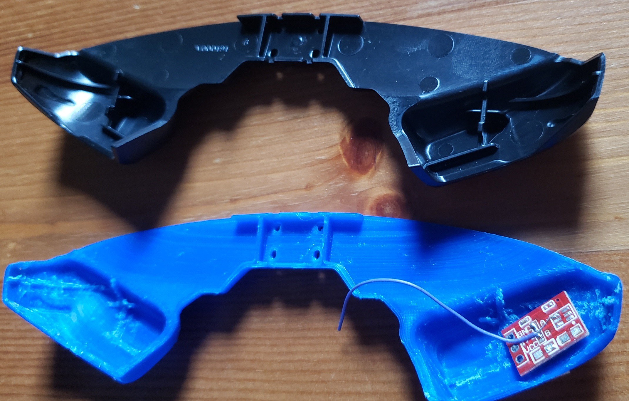
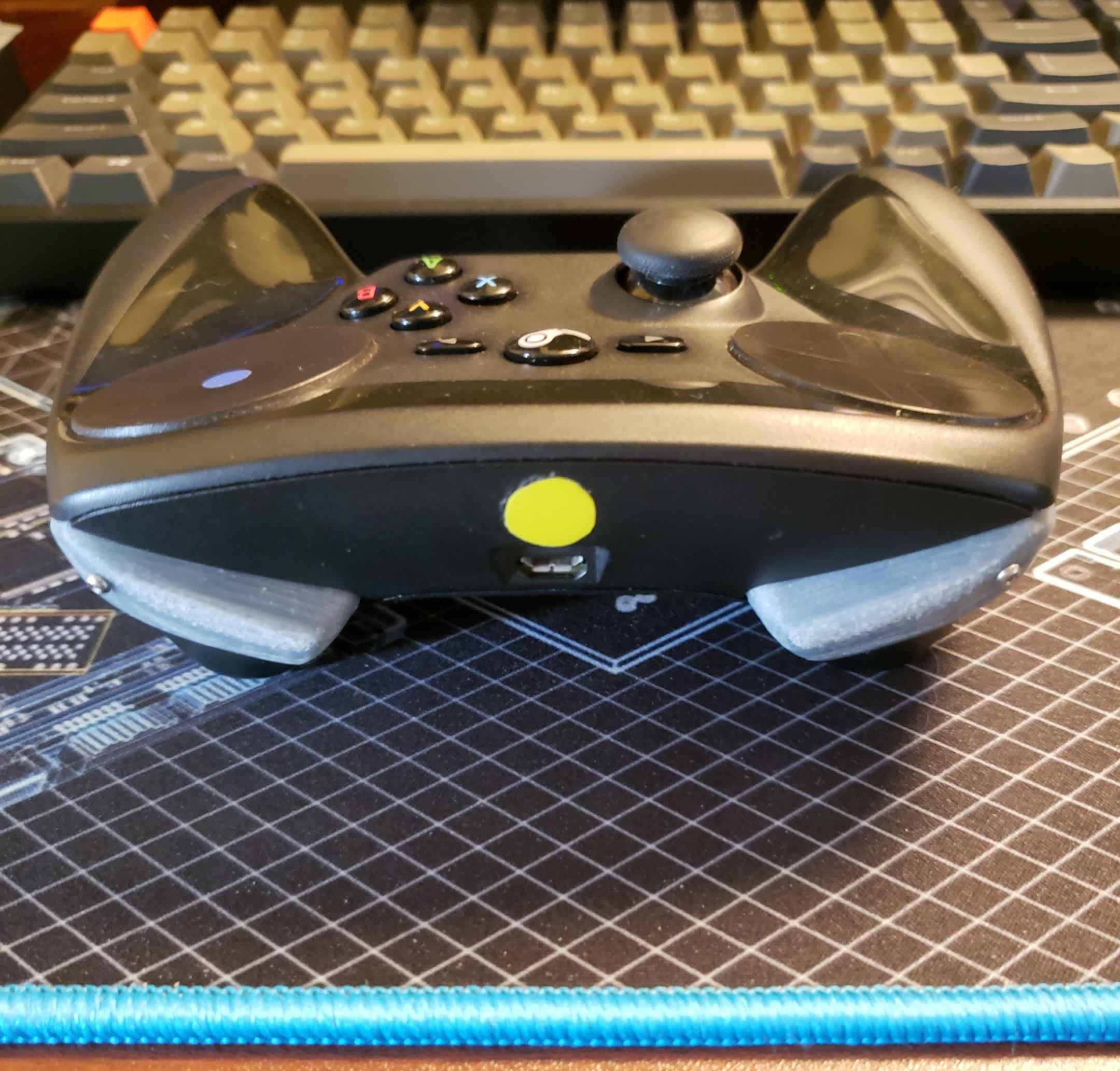
At this point, I'm confident that the `ttp223` module itself can fit entirely inside of the original plastic button for the Steam Controller's bumpers with ample room to spare. However, there's some framing inside the original bumper plastic which will get in the way. To avoid damaging the original plastic parts, I will 3d-print a new bumper. Someone's already done most of the legwork necessary by converting the full CAD files into a more printer-friendly set of `stl` files [steamControllerSTL]. The original parts are meant for injection-molding, they're very thin and curved. It took some trial-and-error to select an orientation that didn't waste too much material on supports while also not warping. I recommend you print the part with the buttons facing downwards. You'll end up having to do a fair bit of sanding to the button surfaces this way, but it's much easier than cleaning the supports out of the button cavity itself.
Speaking of the button cavity, I took a dremel to the plastic framing inside the button cavity itself. The framing functions to strengthen the thin plastic, and to focus the force of the button press onto the microswitch. I don't want that microswitch to be touched, and don't intend to actually press these buttons at all, so I removed all of it with a dremel. Note: I'm printing in basic PLA because I'm a total novice at 3D-prints, and my library allows me to submit jobs inexpensively.
![]()
Bumper replacement in blue, all sanded and dremeled.At this point, I've also tried attaching the `ttp223` boards to the PLA print with a couple methods, determing that hotglue holds best. Now I discover that the touch surface is so sensitive that it can read my finger through the 3D-printed plastic. This is a bonus as it means I can just glue the boards to the backside of the bumper buttons and not have to resort to using metal lugs or screws to carry capacitance from my finger to the `ttp223` input pin.
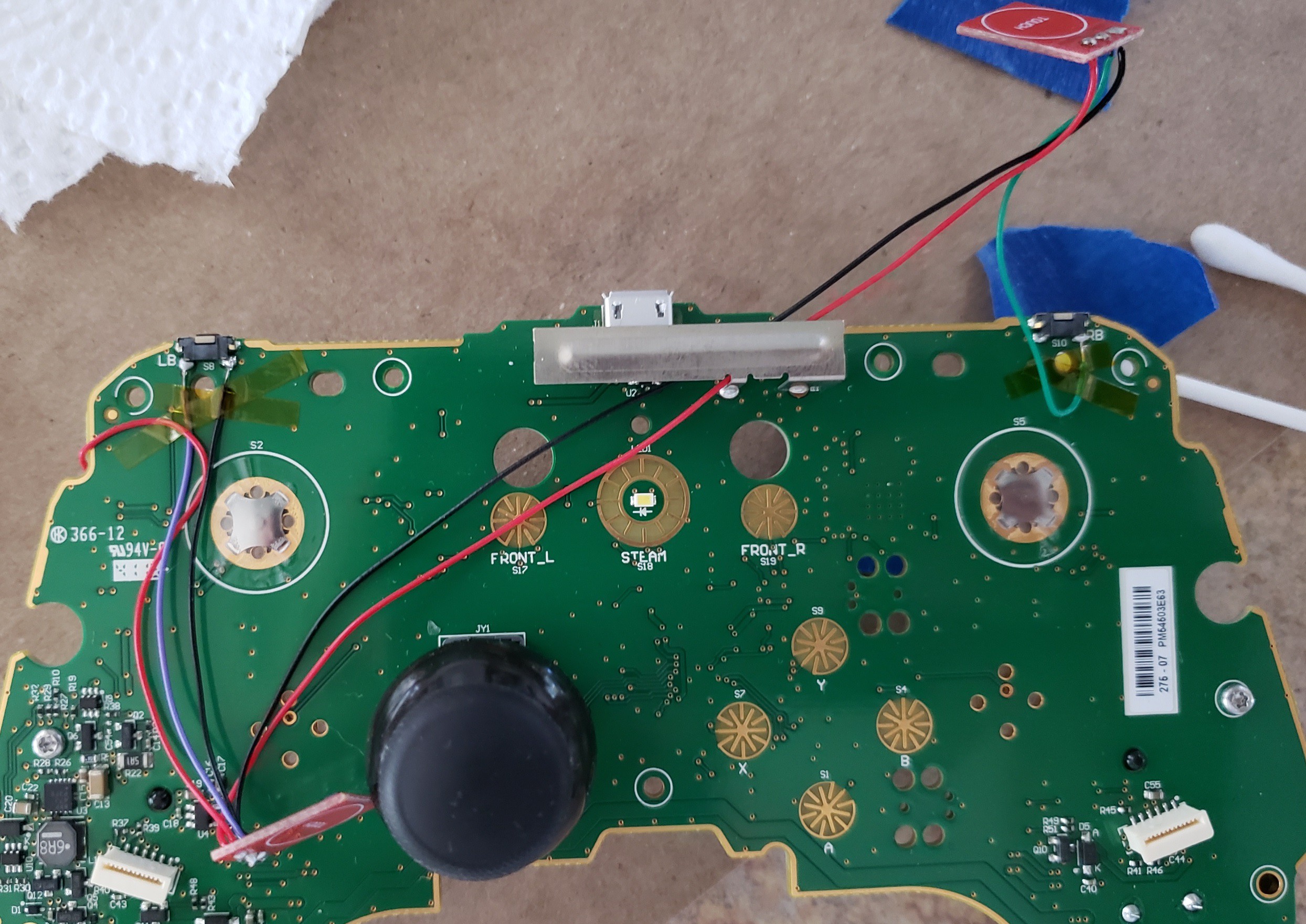
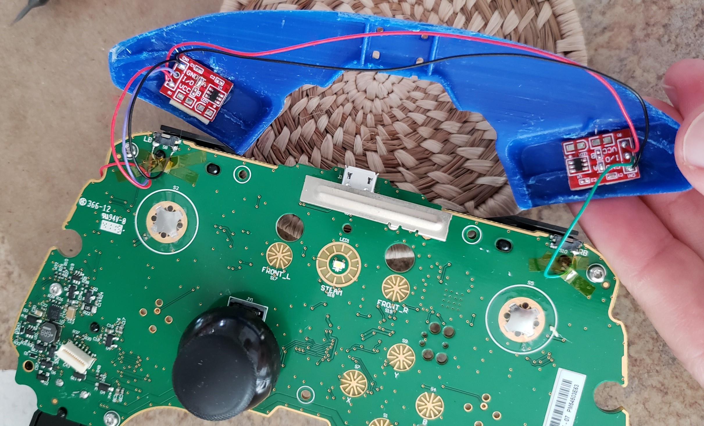
Time to prepare some of the `ttp223` modules for use inside the controller. I desoldered the LEDs since I won't see it and perhaps reduce the power draw on the batteries. I also soldered jumper A on both modules. Then I started soldering to the steam controller PCB:
- I connected to input voltage from the test point noted in the earlier section (red wire; there's a few pictures up the page a bit). That wire had to wrap around to the backside of the PCB.
- I connected to ground using one of the pads meant for the microswitch (black wire).
- I connected each module's input to the active pin on each of the microswitches (green and purple).
- I'm chaining ground and input voltage between the two modules to bridge the gap between the two bumper buttons.
![]()
Yes it's entirely too much solder.Next, I glued the touch sensors into place inside the 3D-printed bumper. I powered on the controller to confirm everything was wired up properly, and finally time to reassemble.
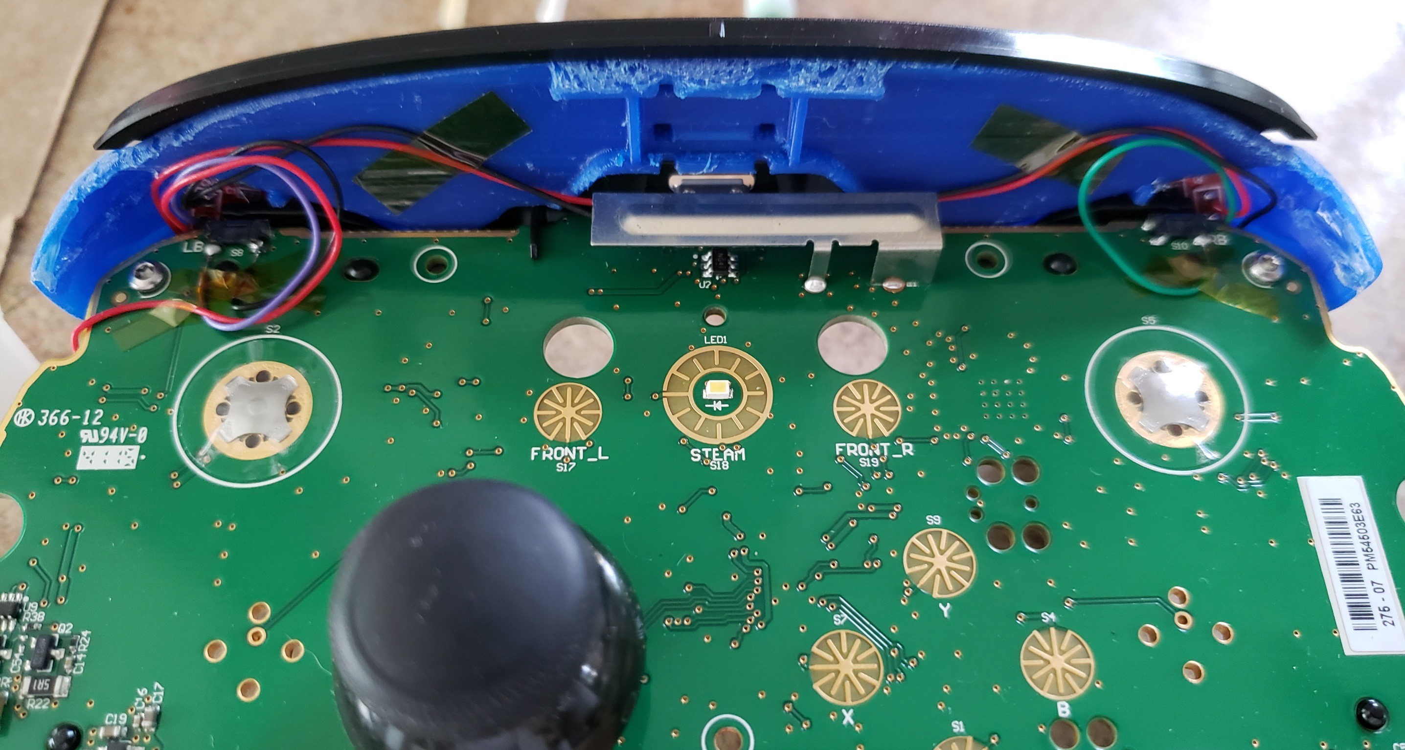
![]()
Sensor modules glued into place![]()
Reassembling the controller. -
4Minor Tweaks and Cautionary Notes
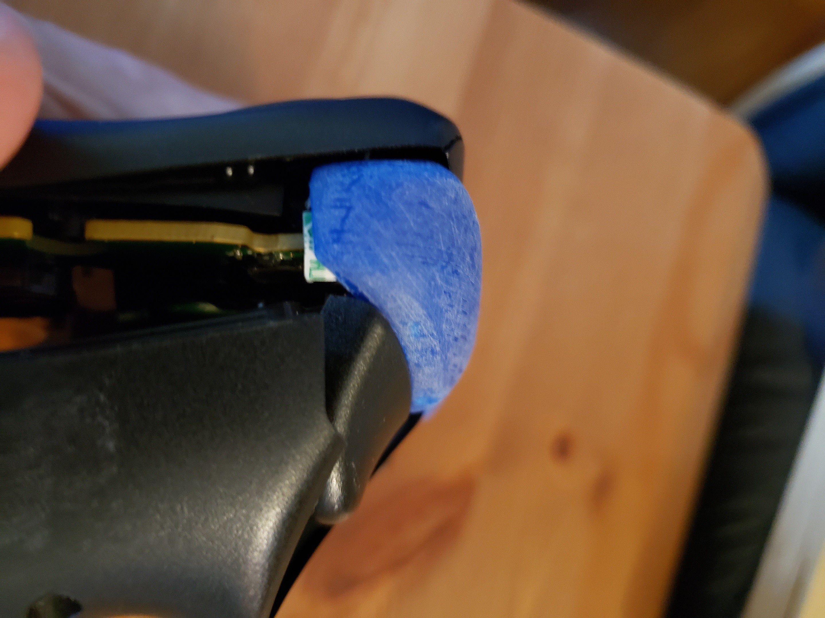
While reassembling, I realized that the bumper wiggles around freely without the tension provided by the plastic framing (the stuff I dremeled out to make room for the touch sensor modules). I don't want to accidentally flex the bumpers and cause the wires or touch module to be crushed, so I added a small piece of double-stick tape between the 3D-printed bumper and the edge of the PCB.
![]()
One tiny piece of double-stick tape under there. It's held for 6 months.
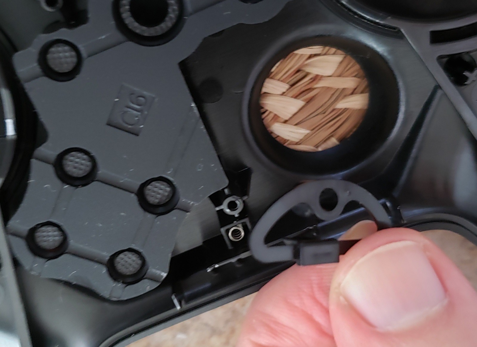
When you're disassembling the steam controller, you must first remove the lower shell of the controller. Then you can unscrew the PCB and lift it away from the upper shell of the controller. At this time, every tear-down warns you to be careful not to stress the ribbon cables which connect the round touchpads to the PCB. The teardowns neglect to mention this thin plastic D-shaped piece between the button membrane and the thumbstick. It's held in with spring tension, and you'll be so focused on the fragile ribbon cables that you won't notice this piece, as well as its impossibly tiny little spring, go flying off across the room. Be careful not to lose this piece.
![]()
I'm a tiny piece of plastic, and a spring which can fall between your floorboards!
Finally, let it be known that gluing the capacitive modules into place is awkward and requires finesse. I completed all soldering before gluing the modules into place, and that was a mistake. I should have soldered wires to the modules (and the modules to each other), then glued the modules and wires into place on the 3D-printed bumper. Only after gluing should I have soldered the wires onto the PCB.
-
5User Review and Improvements for Version 2
I applied this modification over 6 months ago and have been using this controller exclusively ever since. I haven't suffered any failures, so my amateurish soldering has held strong. I'm pretty happy with the results, but there are some issues to fix:
- The 15-second touch limit has only been an issue for one instance in one game: Those darn Strategems in Helldivers 2 can be a pain to type in , especially when you mess up halfway through. Then the touch sensor acting as your left bumper suddenly stops sending any signal and you rage out. If I really wanted to fix this, I could source the 6-pin chip alone from a parts seller rather than a random Amazon page. I can also buy other variants of the same module: the `ttp224` supports 4 touch sensors and exposes all of the option pins. I'm not ready to learn PCB design for this project yet!
- The touch sensor is almost *too* sensitive and placement is important: The touch sensor picks up my finger even hovering 2-3 mm above the plastic surface. The sensor will pick up my finger even if I slide it to the upper part of the trigger (where it pivots). I've accidentally thrown a grenade (via right bumper) into my friend's back a few times! I could fix this by adding a capacitor to the module (as noted in the `ttp223` documentation). That would take some trial-and-error, or a trimming/variable capacitor.
- The auto-sleep function of the Steam Controller no longer functions: The controller should sleep itself after 5 minutes of inactivity. This isn't a big deal to me, as I hated that the controller would turn itself off if I got up for a beer break. If you try this at home, you may unexpectedly eat batteries if you forget to turn off the controller.
-
6Version 2
![]()
A new problem came with the summer heat: one of the touch modules suffered intermittent failures. It would function for several minutes and then would not function for a time afterwards, only to be functional again. Power cycling the device didn't appear to help. Nothing physically wrong with the circuitry; either the `ttp223` module broke or something is interfering with the electrostatic environment regarding heat and humidity. At any rate, time for some iterative improvements:
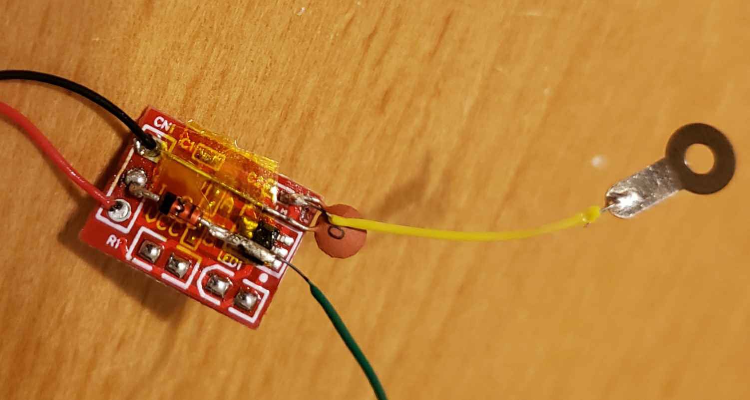
- Correct the over-sensitive touch module by adding a small (10pf) capacitor to the `ttp223` module.
- Make the touch sensor more explicit by attaching the touch sensing pin to a small (2mm metric) bolt screwed into the 3d-printed bumper. You also cut the trace connecting the large copper touch surface on the back of the module.
- Eliminate signal feedback by adding `1N4148` [signal_diode]s between the I/O port on the `ttp223` module and the controller's motherboard.
![]()
Modified ttp223 module.
This new design looks a whole lot more like a prototype with those through-hole parts soldered onto smd pads. Version 3 will require a custom PCB, and possibly mount it outside of the controller shell to address some concerns:
- Working with these wires in such a tight space is frustrating. Next version is going to use longer wires with a lot of slack.
- Re-opening the controller is putting wear and tear on the shell and the plastic screw-posts. Next version will route the wires outside of the case so that all the capacitor-tweaking and module replacements can be achieved without re-opening the controller again.
- Directly soldering the wires to the module results in a more compact build, but maybe adding headers would be a better idea.
Steam Controller Capacitive Bumper Mod
I find the bumpers on the Valve Steam Controller to be difficult to push, so let's replace them with touch sensors!
Discussions
Become a Hackaday.io Member
Create an account to leave a comment. Already have an account? Log In.