-
Porter v5 - a big upgrade!
06/25/2024 at 22:10 • 0 commentsPorter v4 ran directly from a Lithium Polymer (LiPo) battery, which has an output voltage ranging from 4.2V to about 3.0V (depending on the cut-off of the protection module). In addition, the pre-amp had a passband gain of about 4.3. That means a peak voltage of less than 500mV is still enough to cause the pre-amp to clip. A hard bass slap or a hard strum of all 6 guitar strings can easily exceed 1V peak, which means I really want a supply of at least +/-4V, ideally +/-5V to allow some headroom. This would match up well with the typical 9V supply used by effect pedals.
Unfortunately, my pre-amp and headphone amp chips were both design for low-voltage operation, with a 5.5V max supply. That meant I had to select completely new parts. However, this turned out to be a good thing! I found a new headphone amp chip with really fantastic specs - the Analog Devices (formerly Maxim) MAX97220E. This chip had even better THD (total harmonic distortion) specs than the previous two I was using, plus it enabled stereo output with no DC-blocking caps. On top of that, it had a built-in charge pump to produce its own negative supply (saving me selecting and placing another part). And it was still only $1.50!
One downside is that the new chip uses a QFN (quad flat no-lead) package, which isn't as friendly for hand-soldering or repair. The previous parts were available in SOIC (small-outline integrated circuit) packages, which at least had exposed leads. I've personally found it to be a worthwhile trade, though (and yes, I've hand-assembled a bunch of them with a hot air gun).
I also needed to select a new pre-amp chip. I went back to the trusty Texas Instruments TL072, the "H" variant of which offers lower power consumption and wider output swing than the other variants. The per-amplifier current draw is comparable to the OPA1671, though there are now two amplifiers instead of one. The THD performance is 3x better, but the noise performance is 5x worse; the headphone amp had higher THD and noise than either pre-amp chip, so it didn't really matter anyway! And the overall THD and noise performance are still quite good.
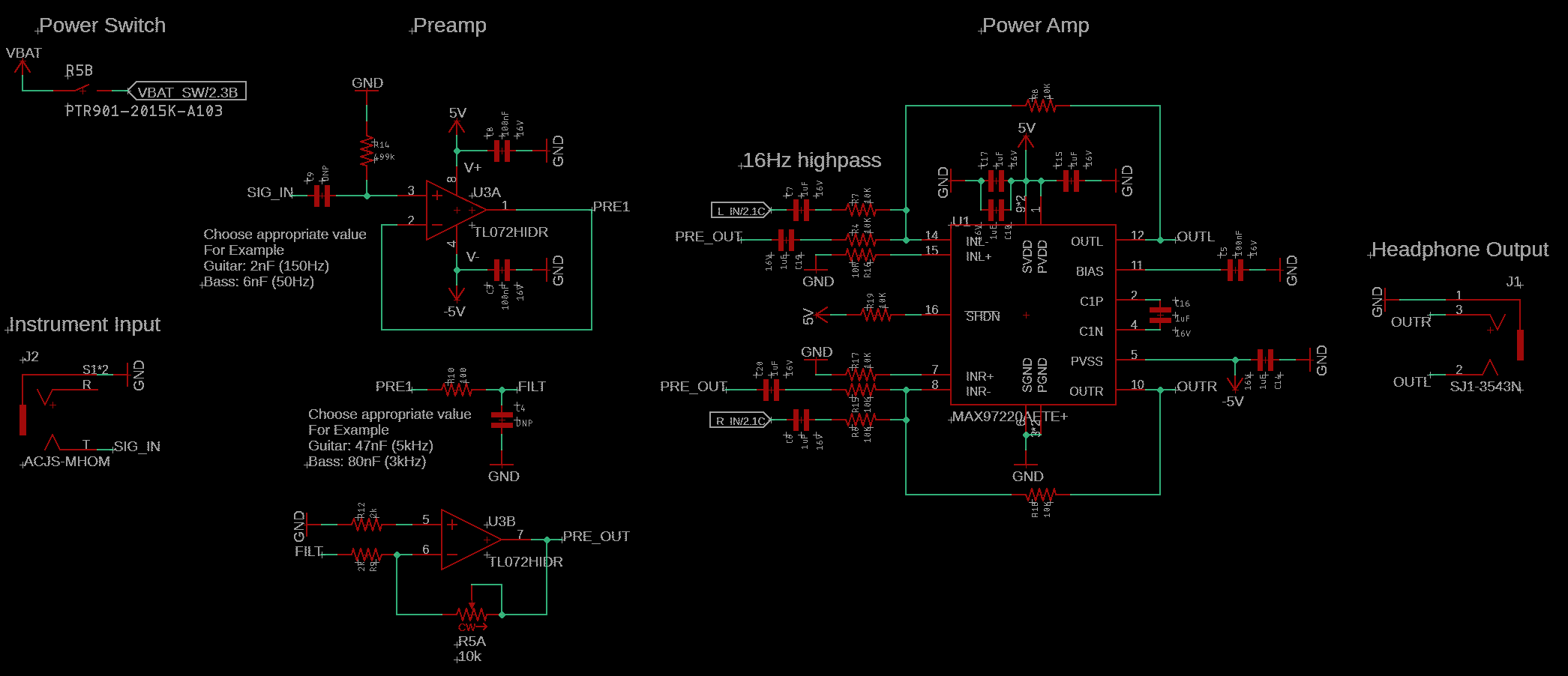
Here's what the audio section of Porter v5 looked like with the new chip selections. Note the -5V supply generated from the headphone amp, which is shared with the pre-amp. Note also that the pre-amp gain is now variable, which helps reduce the likelihood of clipping even further.In order to minimize the possibility of clipping as the battery discharges, I decided to also add a boost converter, which would provide a fixed +5V supply. I chose the Texas Instruments TPS613222A, which uses minimal external components and offers great efficiency (82-94%) over a wide load range. I also added a power indicator LED, to help make it clear when Porter is on and operating.
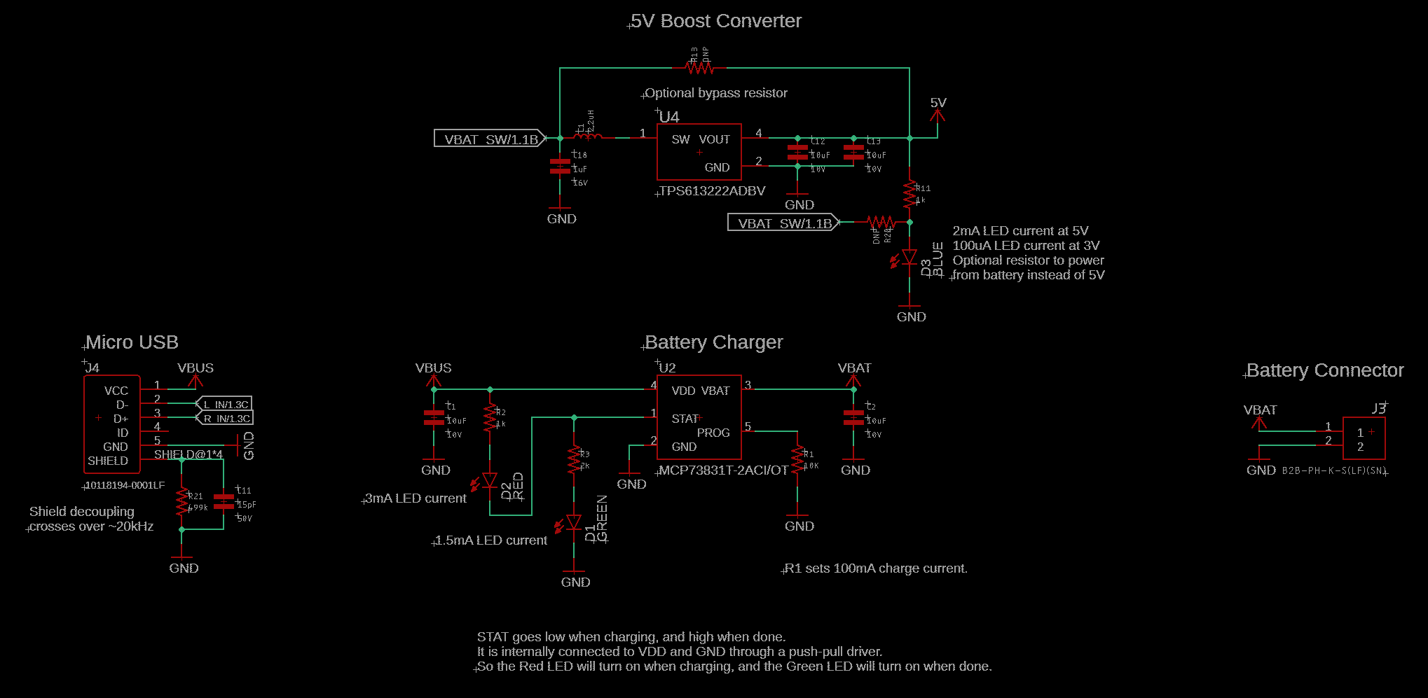
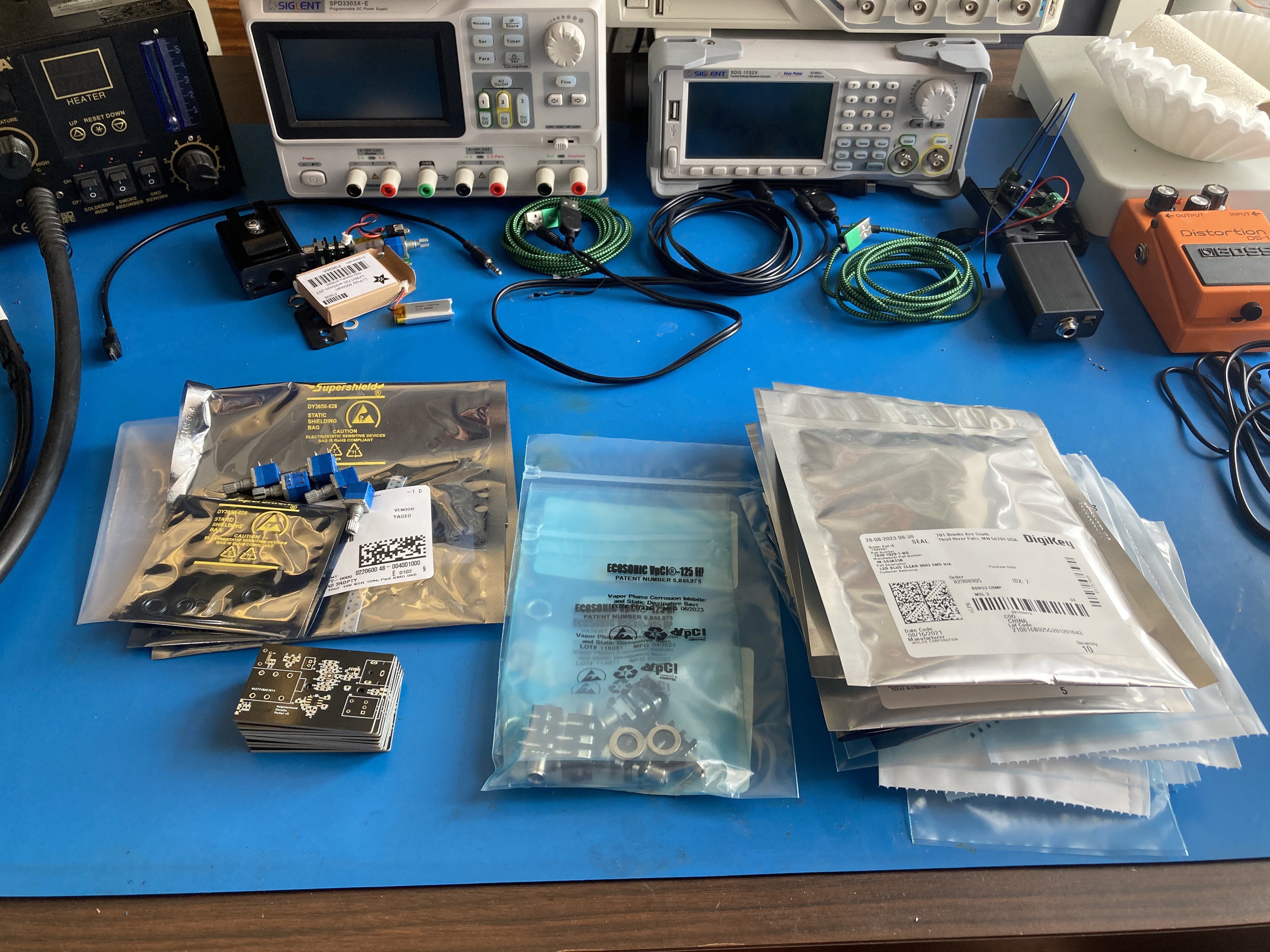
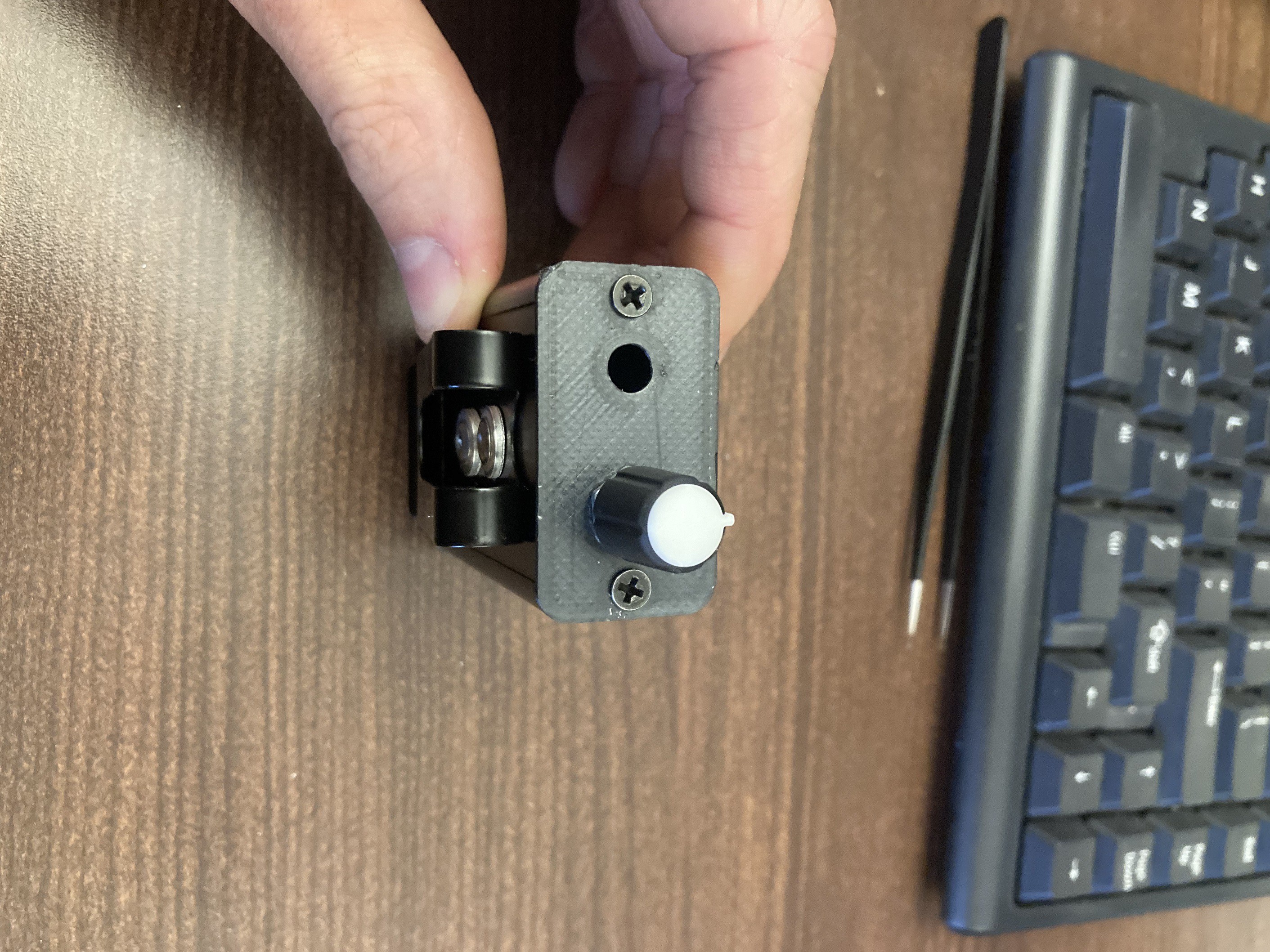
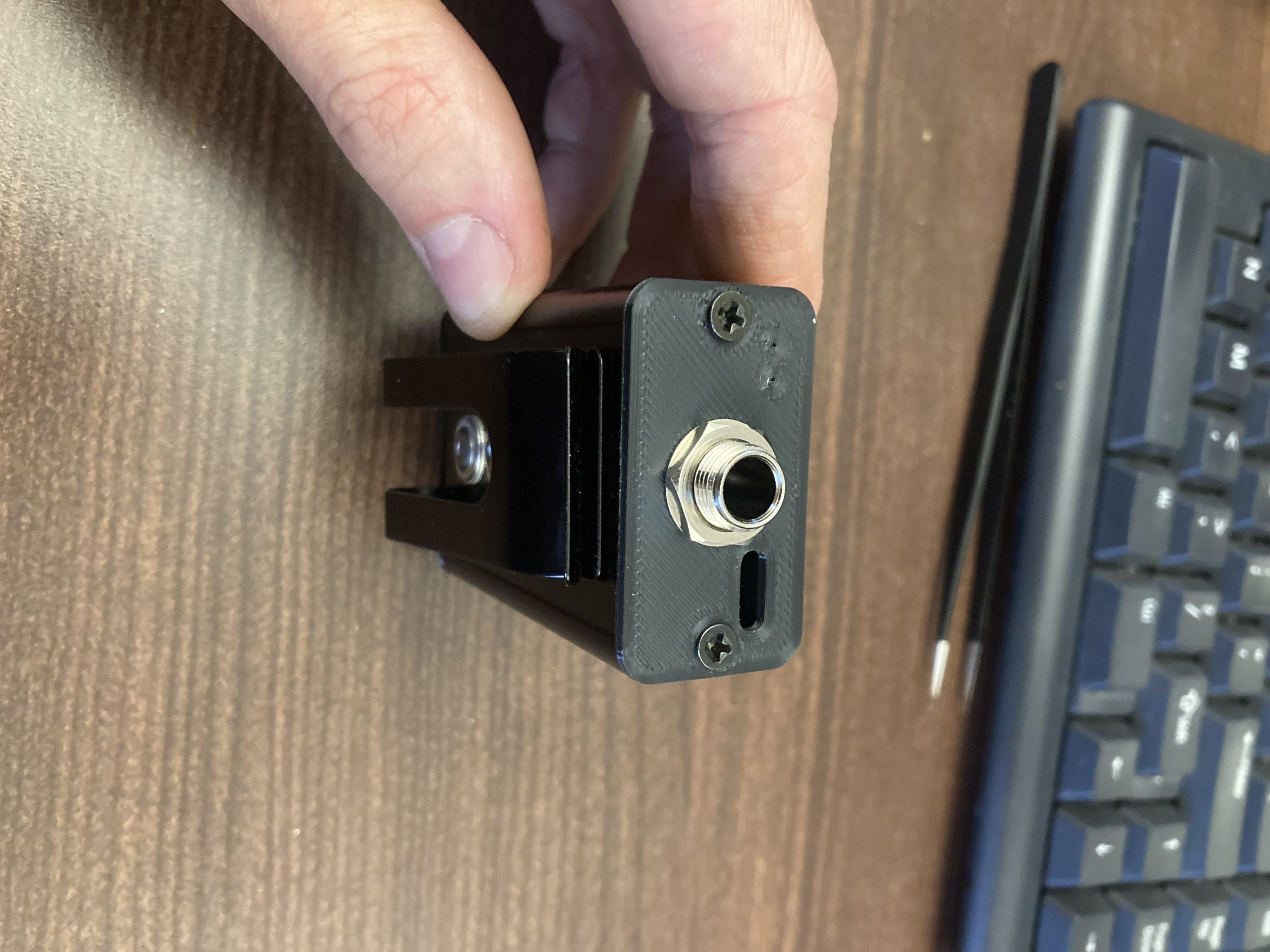
Here's what the power section of Porter v5 looked like with the boost converter added.Photos of v5 test build and a close-up of the PCB itself (now in black!):
![]()
![]()
-
Porter v3 and v4 - preamp and volume control
06/24/2024 at 20:46 • 0 commentsPorter v3 introduced a couple of new features to address feedback from my v1/v2 beta testers and from my own personal experience using it as a practice tool. My number one point of feedback was to please add a volume control. I also personally wanted to be able to play along with songs I'm trying to learn, or a generic backing track when practicing improvisation. Adding volume control was straightforward - just replace the headphone amp's feedback resistor with a pot(entiometer). Adding the capability to play along with music was a little more tricky.
I didn't have space in the enclosure for another input jack, so I started looking into ways I could get the USB port to multitask for me. Having done some work with USB-C in my consulting job, I was aware of an Audio Adapter Accessory Mode that would transmit analog audio over the USB data lines. I only needed half an excuse to move to modern, always-plugs-in-the-right-way USB-C, and that was it.
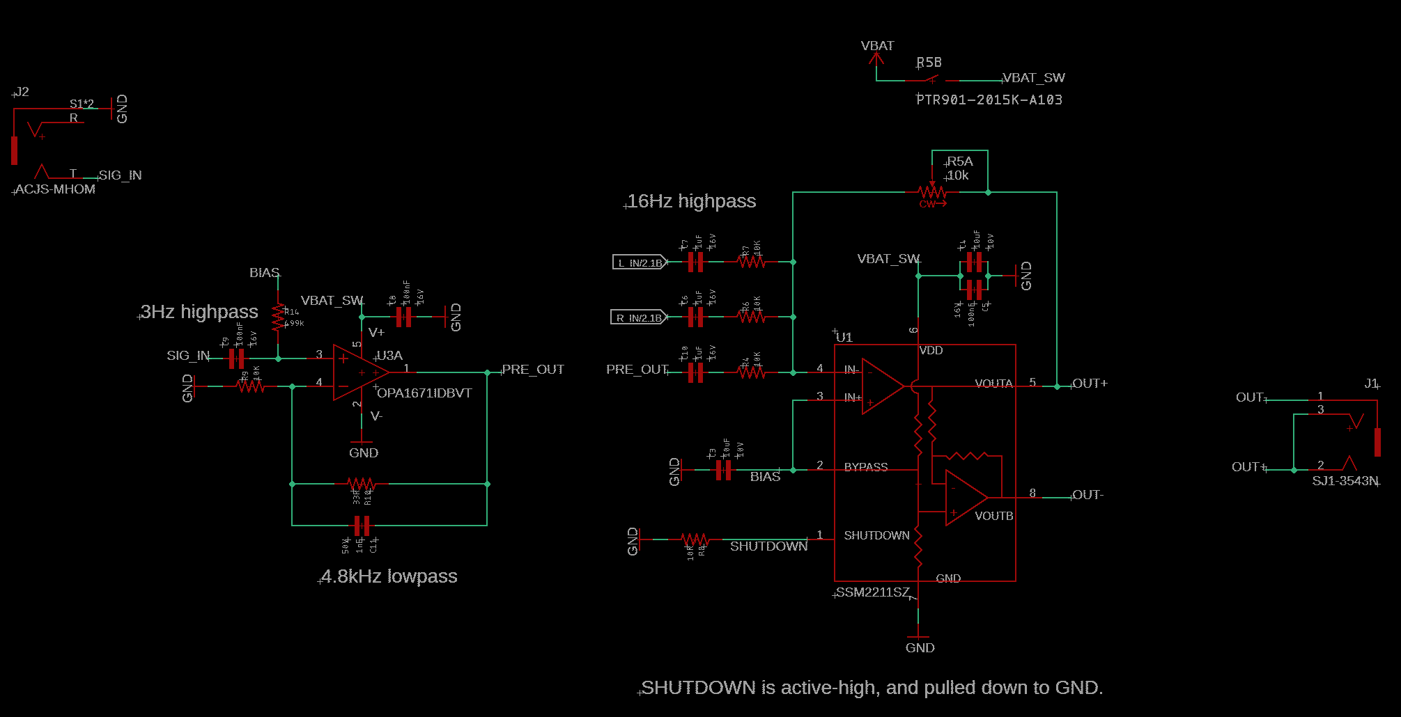
However, this change also required that I add a separate pre-amp to the design, because I didn't want the audio to be filtered in the same way as the instrument signal. So I added a Texas Instruments OPA1671IDBVT, which is a nice low-noise, low-distortion, rail-to-rail, low-ish-power, single-supply audio op amp (and it's only a buck!). The headphone amp generates its own mid-supply bias, which I borrowed to bias the op-amp as well. I also tied the op-amp's negative supply to the same shutdown line I used to control the headphone amp power state. This wasn't strictly necessary, but seemed like a neat trick that could save some power (the line is active-high, which would "shut down" the op amp by making its supplies equal.)
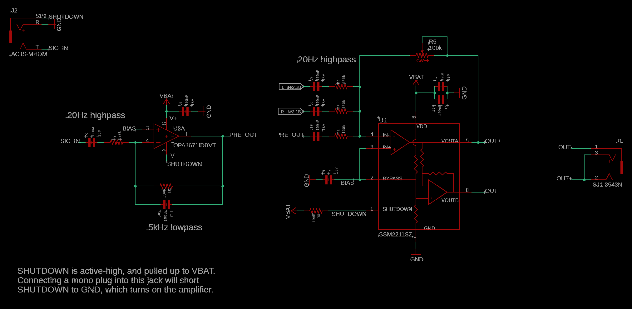
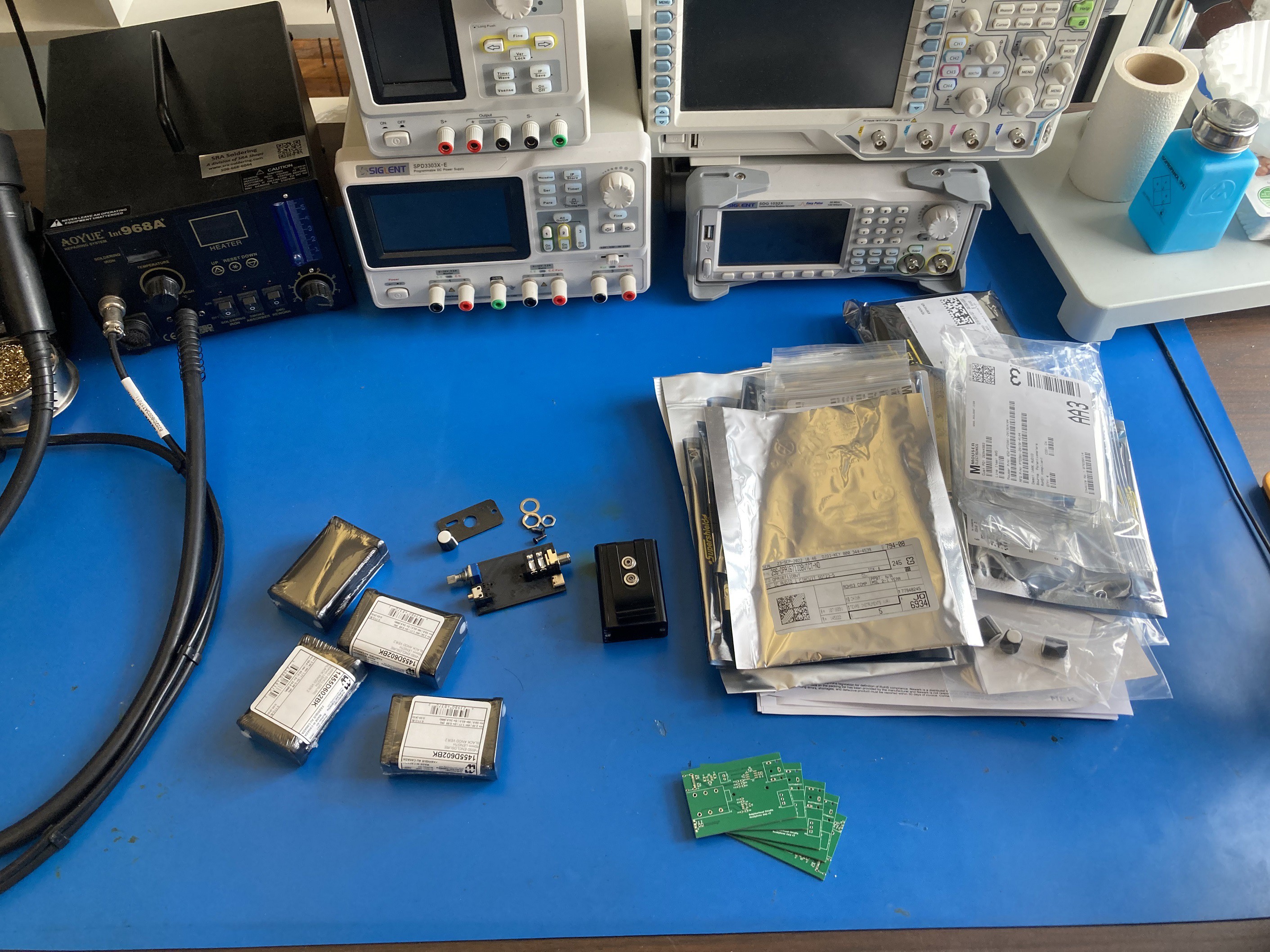
Here's what the v3 schematic looked like:And here's what it looked like as I was getting ready to build up some test units to share with friends (note the 3D printed board in black, next to the Hammond enclosures):
![]()
![]()
At the time, it seemed like Audio Adapter Accessory Mode was well-supported. I found a TI app note demonstrating a reference design for audio adapter support, and figured I was on the right track. Unfortunately, I never got it to work. I later learned that support for this particular feature was kind of a mess, and eventually got deprecated. So it looked like I was moving back to micro USB for v4. There are plenty of micro-USB-to-3.5mm cables available, which use the D+/D- lines as the right and left audio channels, respectively.
I also had been thinking more and more that the input impedance really needed to be higher than 100k to avoid affecting the guitar's tone. I wanted to target at least 499k, based on what I had seen in other pedal and amp designs. The easiest way to do that without introducing unreasonably large resistors (I would have needed 1.5M ohm for a gain of 3) was to move to a non-inverting configuration.
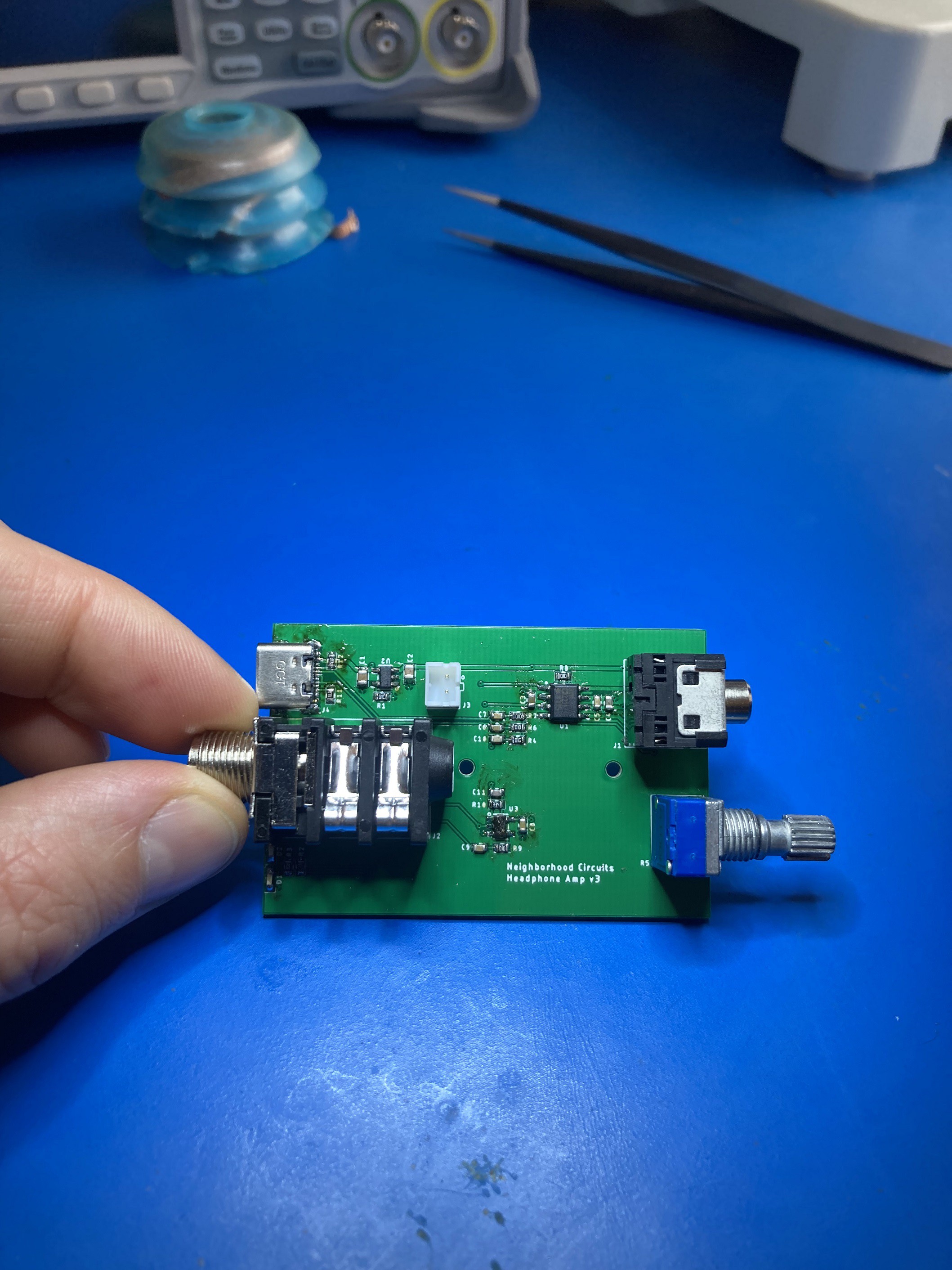
Thinking some more about the user experience, I decided that the automatic power-on/off just might not be intuitive enough. I replaced the 100k volume pot with a 10k pot that had a built-in switch, which would cut the battery power when turned fully counter-clockwise, and apply power (with a tactile "click") when turning up the volume. That seemed natural and familiar enough. There wasn't a 100k version available, but thankfully the presence of a pre-amp allowed greater flexibility in choosing resistor values for the headphone amp. That brought me to the following v4 design:I thought for sure this would be the final revision of Porter... until one of my testers found a problem! It turns out it was possible to make the headphone amp clip when using certain pedals that increased the output level, or with a hard strum of all the strings. I'll share how I solved it in the next post!
(Bonus pic: Porter v4 test build)![]()
-
Choosing an Enclosure
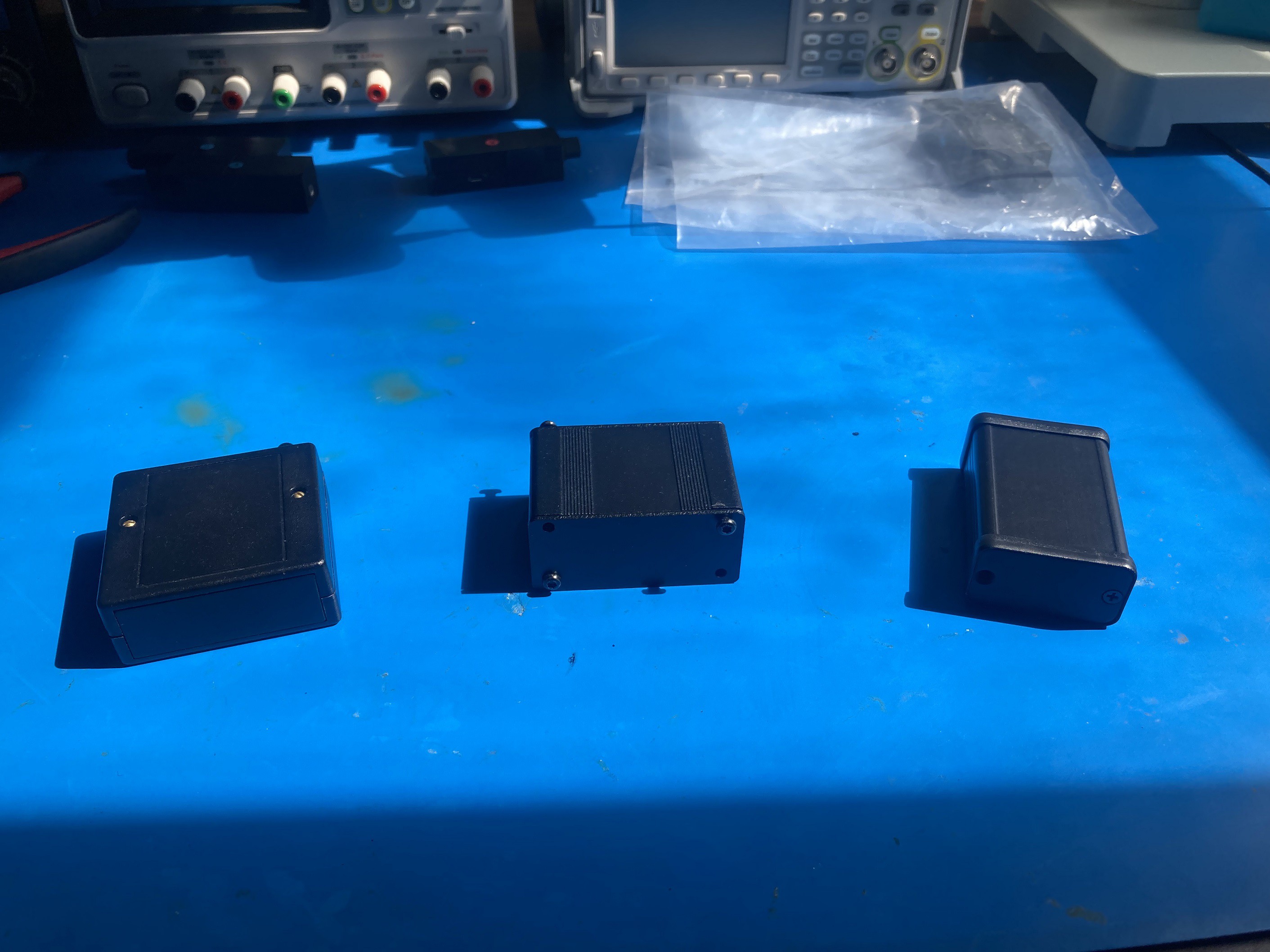
06/24/2024 at 19:39 • 0 commentsBuilding on what I'd learned from testing v1 and v2, I started looking into off-the-shelf cases for the next version of Porter. After digging around a bit, I decided to try out 3 candidates: the PacTec Hand Held, the Box Enclosures BEX SERIES 1, and the Hammond 1455D601BK. Here's what they looked like on my workbench (in the order listed above):
![]()
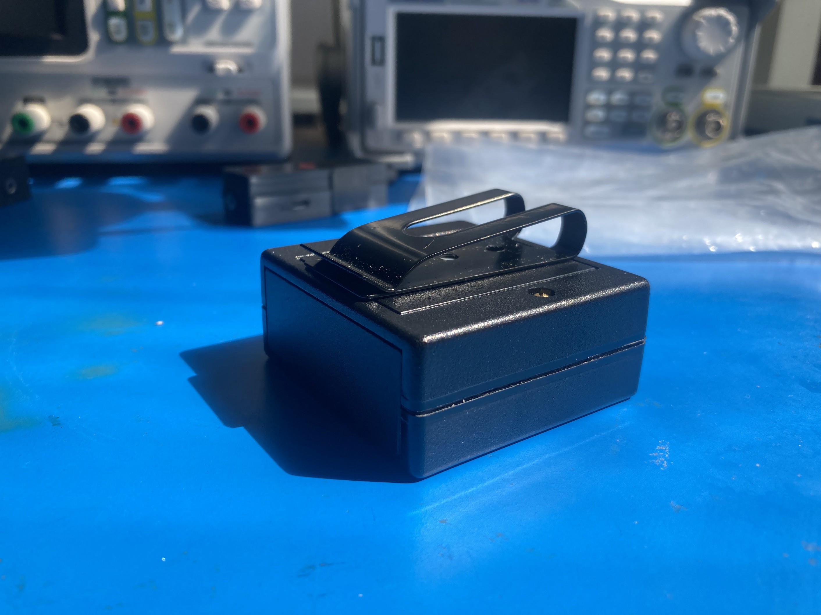
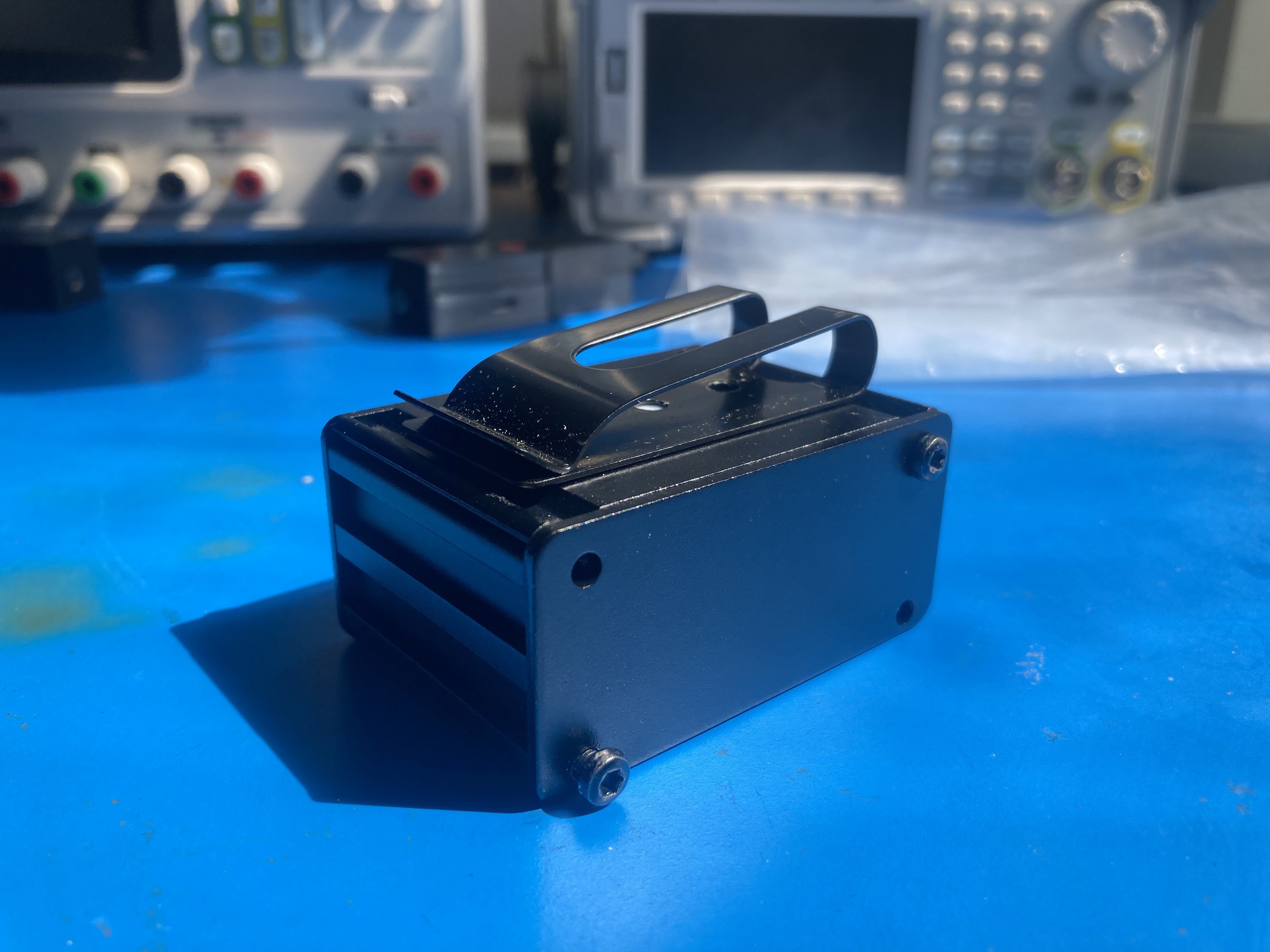
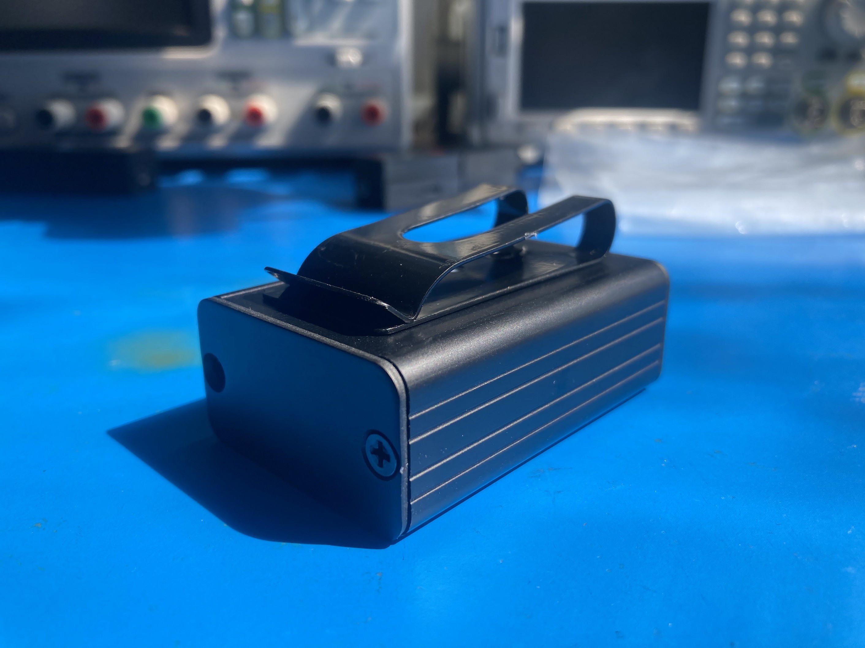
Since I was planning on using a 1/4" jack to allow compatibility with external effects, I didn't have a convenient way to mount the headphone amp to a guitar (existing devices use a permanent plug, which addresses the mounting problem, but introduces the non-compatibility problem; it also is prone to breaking). I figured most guitars have straps, so a belt clip could work to attach it to the guitar strap (or, you know, to a belt). I ordered a candidate belt clip from Alibaba and tried it on each of the candidate enclosures:
![]()
![]()
![]()
The Hammond case was such a standout that I knew instantly it was the way to go. It fit the clip nicely, felt really good in the hand, and had a perfectly understated but distinct visual style. Perhaps not obvious from the pictures is that the PacTec case is plastic, which is reflected in its dramatically lower cost than the other cases (about $4 vs about $12). The end panels can also conveniently be replaced with PCBs for further low-cost customization (as demonstrated by this project). But given how rugged and just darn attractive the Hammond case was, I decided it was worth the extra cost.
My next step was to put my 3D printer to use for the second time: making custom endpanels to help me coordinate component placement with the v3 PCB design. I already had a 1/4" instrument input jack, an 1/8" headphone output jack, and a USB charging input, and I knew I needed to add a volume knob per my beta testers' feedback. As the design matured, I ordered candidate components, 3D printed the PCB, and did some test assemblies to make sure everything lined up before placing the PCB order:![]()
![]()
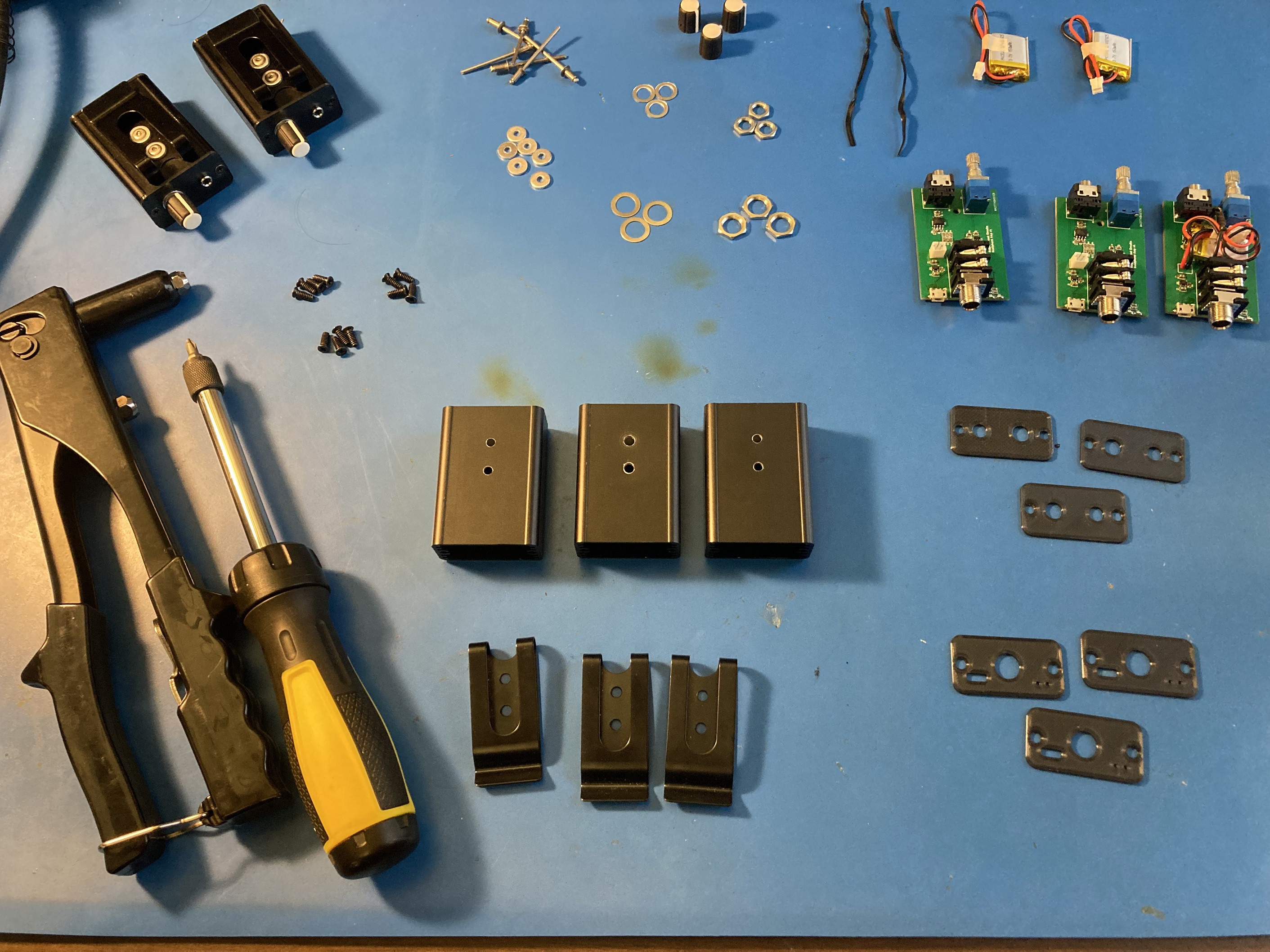
I also did some work on figuring out how to attach the belt clip. After considering several options like tapping threads for tiny screws, using rivet nuts, and using low-profile binding barrels, I went with simple blind rivets in the end. I would have preferred something removable, but between the thin wall of the enclosure and tight clearance to the 1/4" jack and volume pot, the options turned out to be very limited.
![]()
This post is getting pretty long, so I'll cut it here, and talk about the v3 and v4 electrical design in a new post!
-
Porter v1 and v2 - a minimalist headphone amp
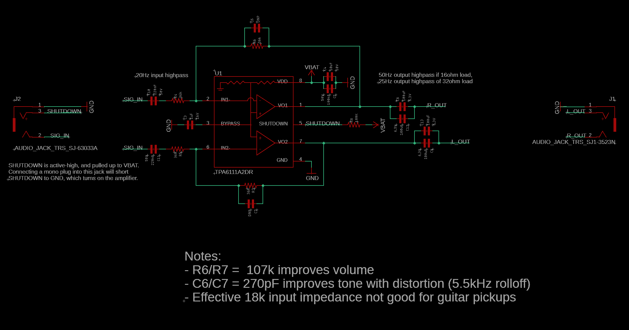
06/21/2024 at 18:49 • 0 commentsMy earliest versions of Porter were extremely minimalist, with no volume control, not even a preamp. It was tiny, and sounded pretty good for playing clean. v1 was based around a Texas Instruments TPA6111A2 headphone amp, which I liked for its low power consumption, shutdown mode, stereo output, and decent fidelity. Schematic snippet below (the rest is just the battery charger, which isn't that interesting).
However, the design of the amp required relatively low input resistor values, resulting in excessive loading of the guitar pickups (which kills your tone). I also wasn't too excited about the large DC-blocking caps it required (mostly from a cost perspective, as I was using ceramics).
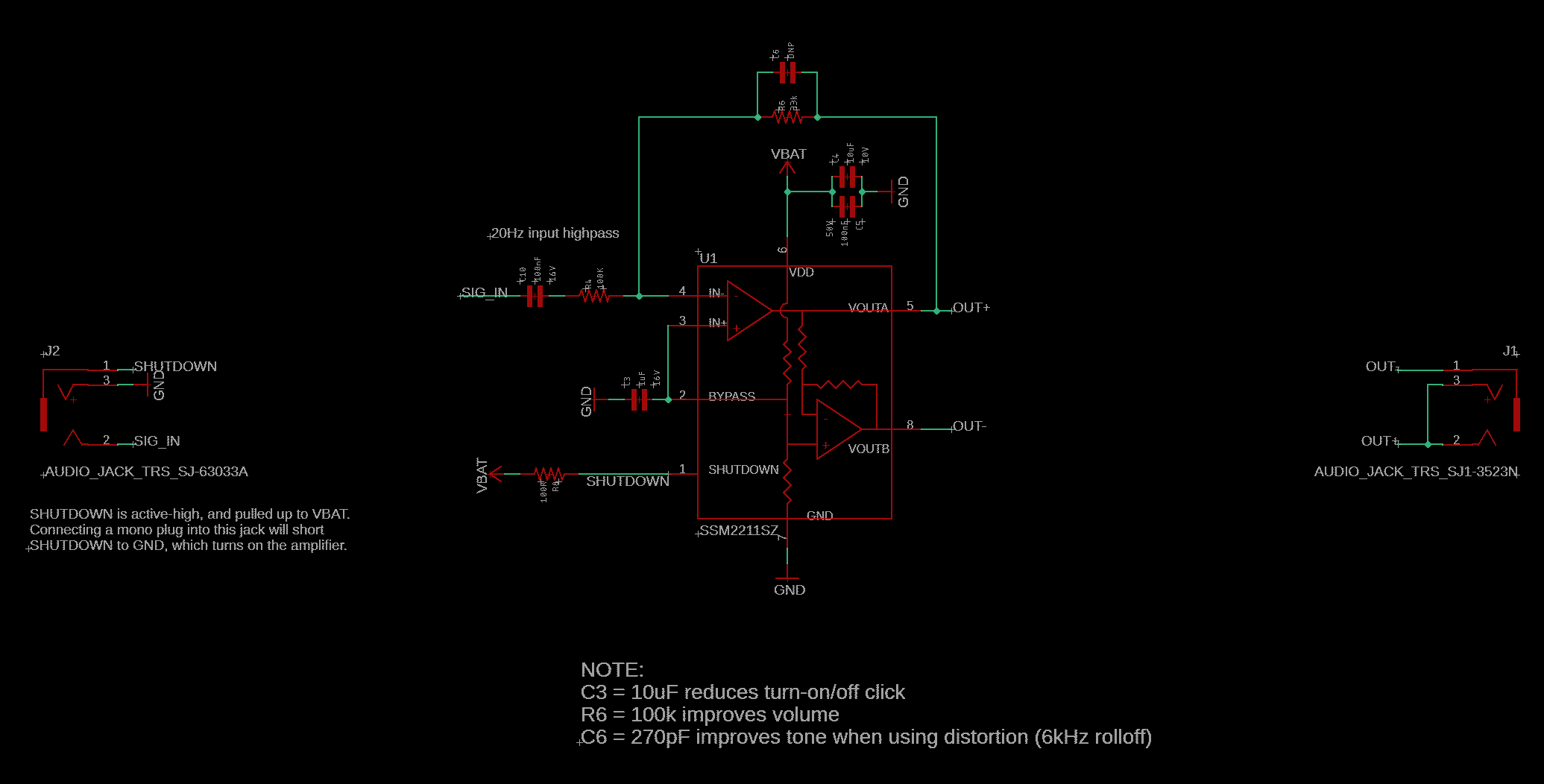
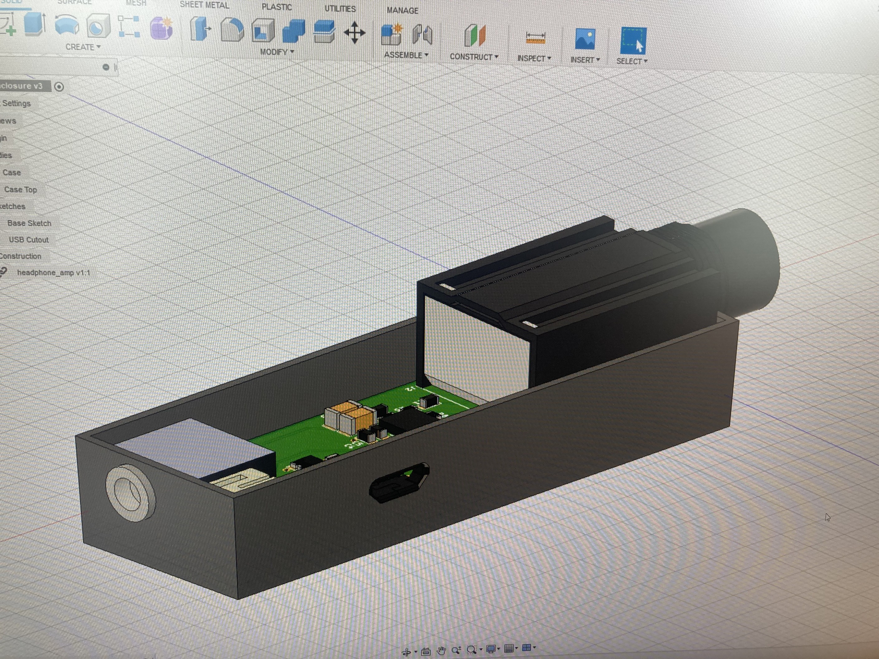
So for v2 I tried the Analog Devices SSM2211, which is a mono headphone amp. The bridged mono output eliminated the need for DC-blocking caps, and the amp allowed for a higher input impedance of 100k ohms. It still had a shutdown mode and decent fidelity. It's a good chip to use for a super minimalist headphone amp, though note that even 100k is still a little low for guitar pickups. Schematic snippet below.I built up a few of these units and wanted to give them to my friends to beta test and tell me which they preferred. But to keep them from getting damaged, I really wanted to put them in a case. I had just gotten my first 3D printer (a Creality Ender 3 v2), so this seemed like a good starter project! Since I designed my boards in EAGLE, I was able to import them into Autodesk Fusion and start designing a case around them.
![]()
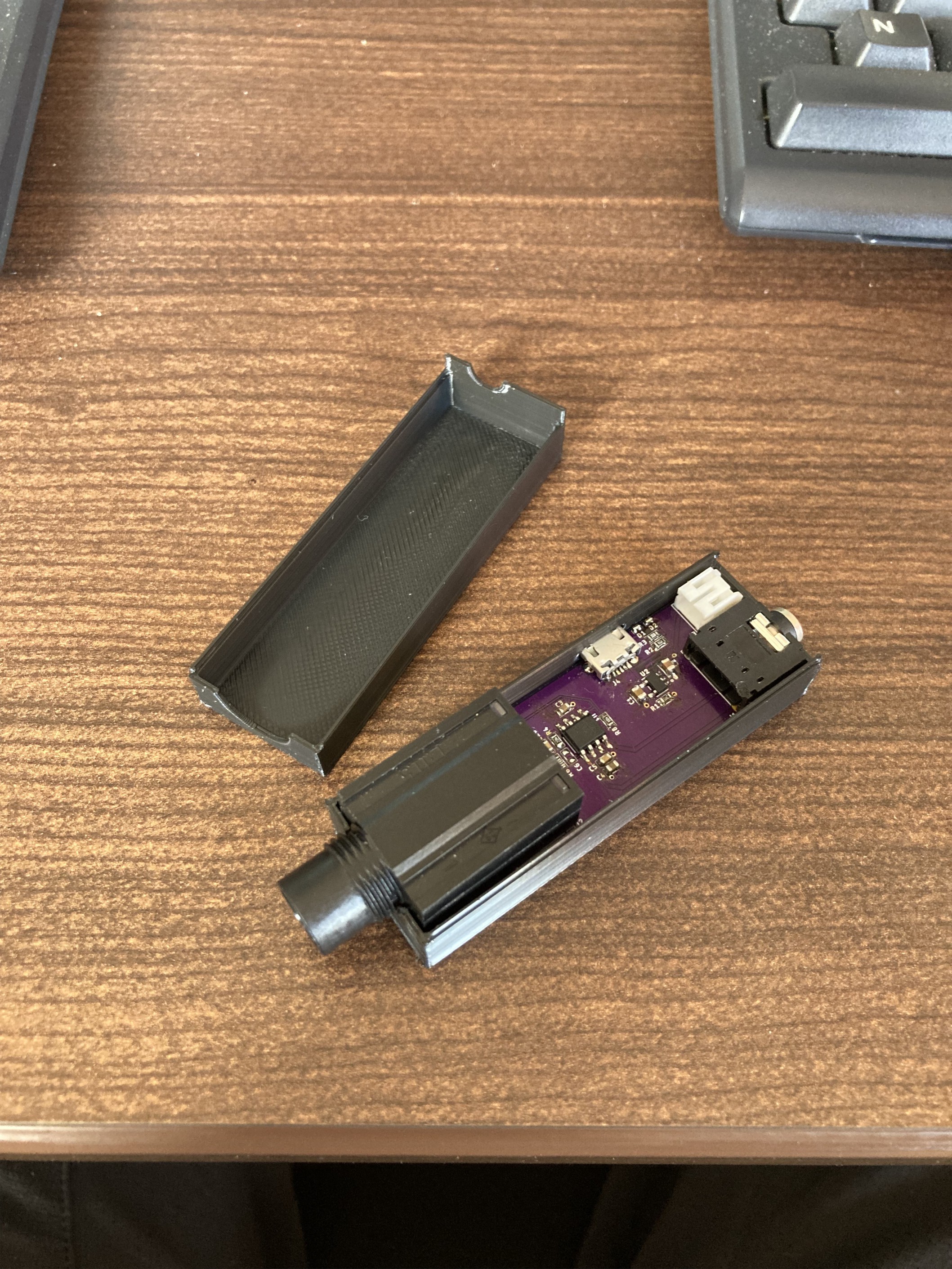
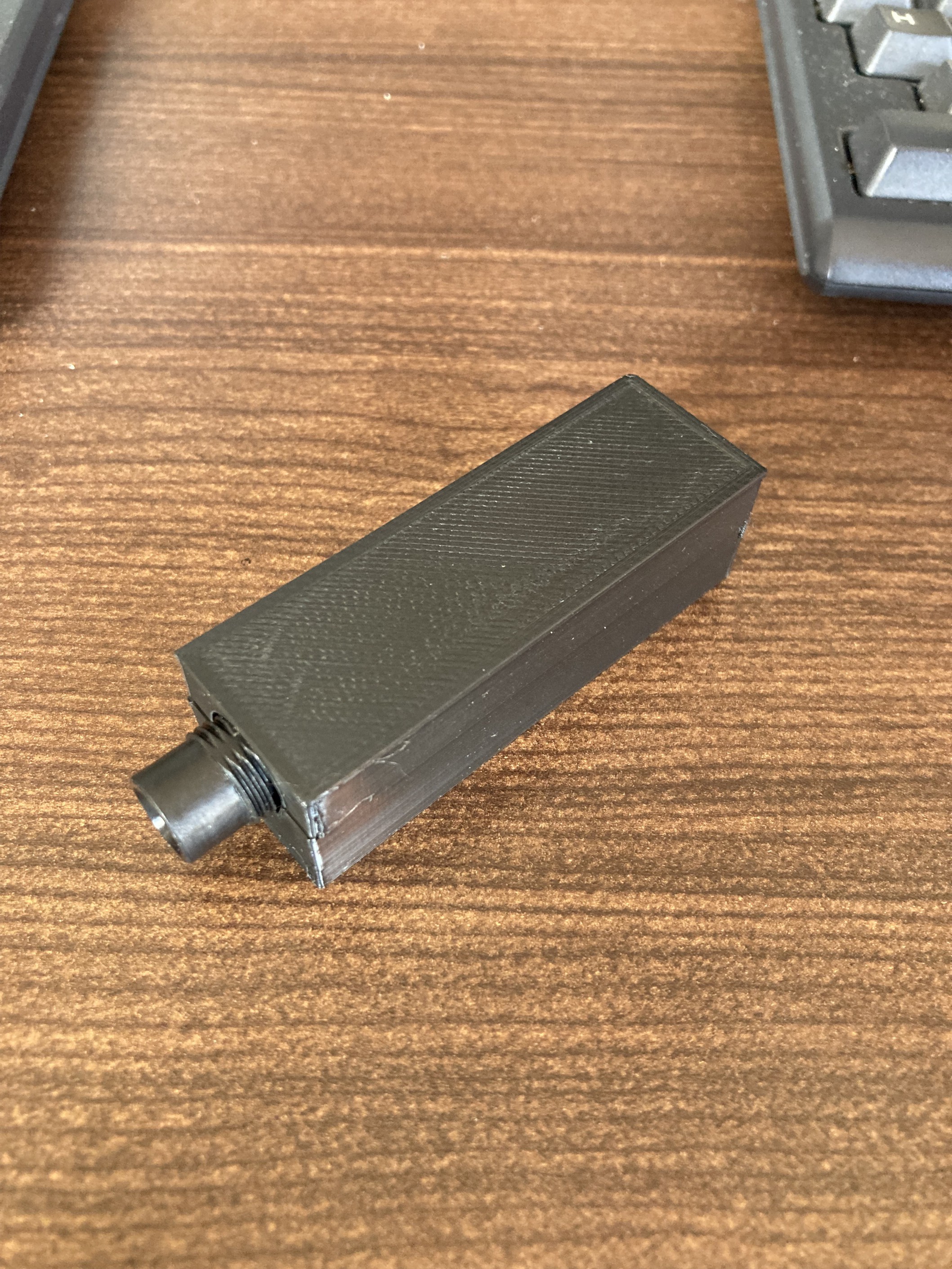
I quickly learned what it means to overconstrain yourself by putting connectors on 3 different faces... thankfully the plastic has some give to it, so I was able to still get the boards into the enclosure. I split the enclosure into two halves and added little bumper rails that would lock together securely enough to stay together, but not so securely that you can't separate them.
![]()
![]()
And those were the prototypes I started handing out for beta testing! The results came back with people pretty evenly split between the two versions. However, one piece of feedback was very consistent: please add volume control! It turns out a guitar's tone can change noticeably when using the passive volume control that's built into it (which is what I was relying on for this super-simple amp). I also wasn't particularly confident in my enclosure design for long-term use (the rails started cracking after a few cycles of assembly and disassembly), so I started looking into some off-the shelf options. More on that in my next post!
 Gavin
Gavin