 Peter
Peter-
1Cut the perfboard
Cut the perfboard to 2" x 3.5" (50 x 89 mm) dimension or 20 x 35 pads.
-
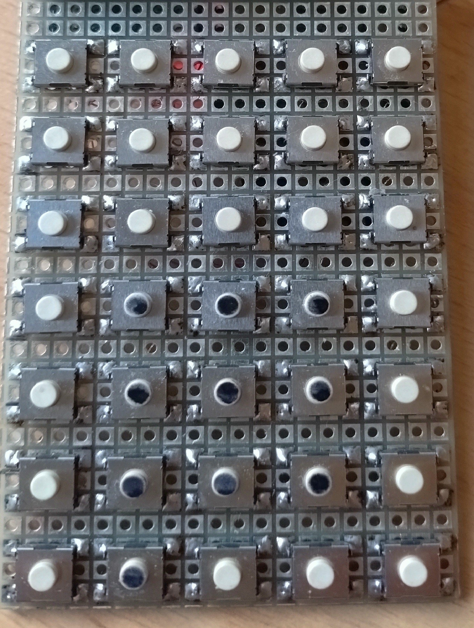
2Solder push buttons
Solder the 35 push buttons to the perfboard top layer. Each button is in the middle of 4 x 3 pads, the grid is 0.4".
![]()
-
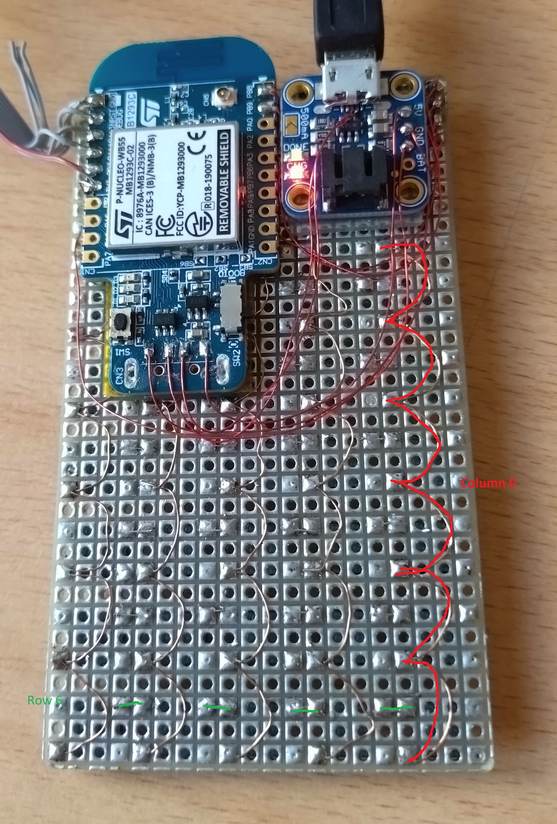
3Wire the buttons
Wire the buttons to columns and rows on the perfboard bottom layer. Build a keyboard matrix without diodes. Pullups are integrated in the MCU.
![]()
-
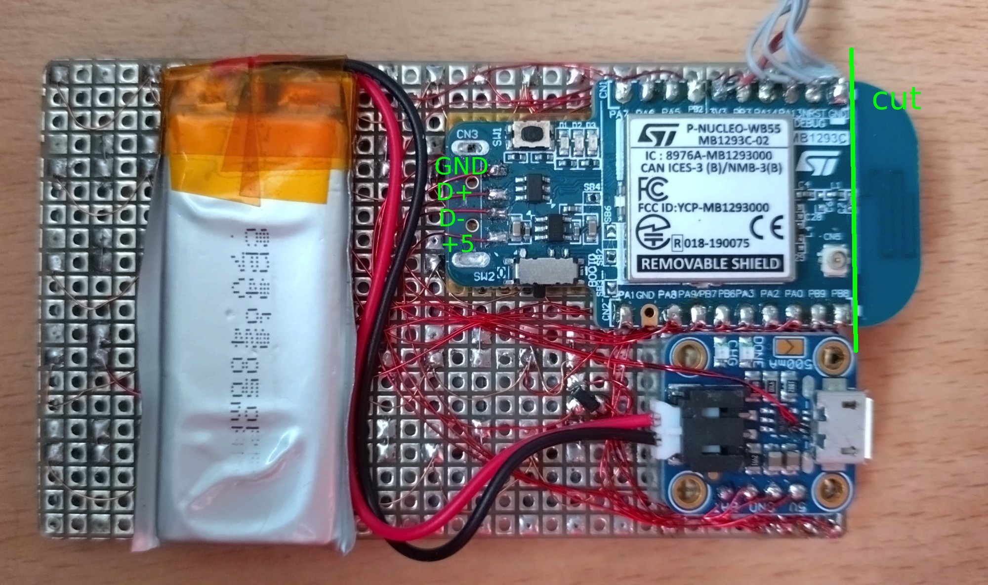
4Mount the dongle
Remove the USB connector from the dongle.
Glue (hot glue, mounting tape) the dongle to the perfboard bottom layer, upper left corner.
If you do not want to use the BLE, cut off the BLE antenna. -
5Mount USB Breakout
Glue (hot glue, mounting tape) the USB Breakout or the Adafruit Micro-Lipo Charger to the perfboard bottom layer.
-
6Wire the buttons to the dongle
Wire the button rows and columns to the dongle.
Description Dongle Function Calculator PB3 CN1.5 SWO ROW0 PB2 CN1.7 ROW1 PA6 CN1.9 D12 ROW2 PA7 CN1.10 D11 ROW3 PB6 CN2.6 UARTRX ROW4 PA9 CN2.7 D9 ROW5 PA8 CN2.8 D6 ROW6 PA0 CN2.3 A3 COL0 PA1 CN2.10 A2 COL1 PA2 CN2.4 D1 COL2 PA3 CN2.5 D0 COL3 PA5 CN1.8 D13 COL4 -
7Wire the JTAG SWD (optional)
Only needed if you want to debug the board.
Description Dongle Function JTAG 10pin GND CN1.1 GND 3, 5, 9 NRST CN1.2 RES 10 PA13 CN1.3 SWDIO 2 PA14 CN1.4 SWDCLK 4 3V3 CN1.6 3V3 1 -
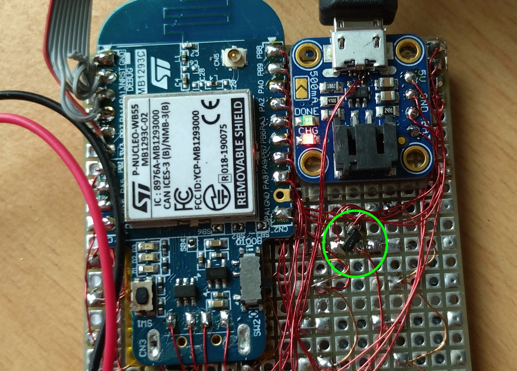
8Place the Diodes (optional)
I use a BAT54C double schottky diode in SOT23 package. Solder the diode to the perfboard bottom layer.
You can also use two 1N4148 diodes.
![]()
-
9Wire the USB connector
USB breakout without charger:
![]()
-
10Mount the OLED Display
Solder or glue the OLED Display to the perfboard top layer.
4TH Calculator
A small pocket calculator for programmers and engineers, a mix between HP-42 and HP-16. Fully programmable in Forth.
Discussions
Become a Hackaday.io Member
Create an account to leave a comment. Already have an account? Log In.