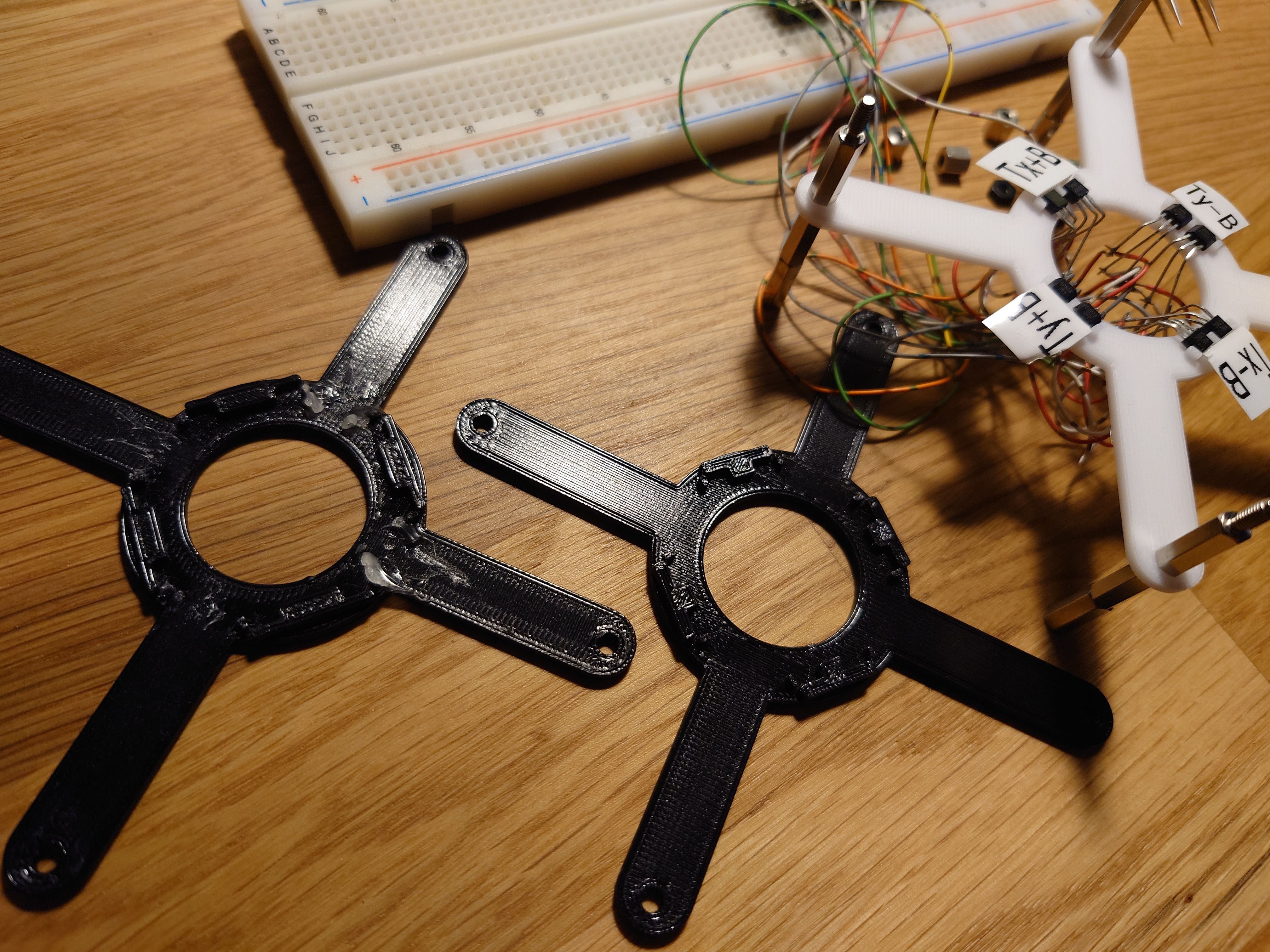
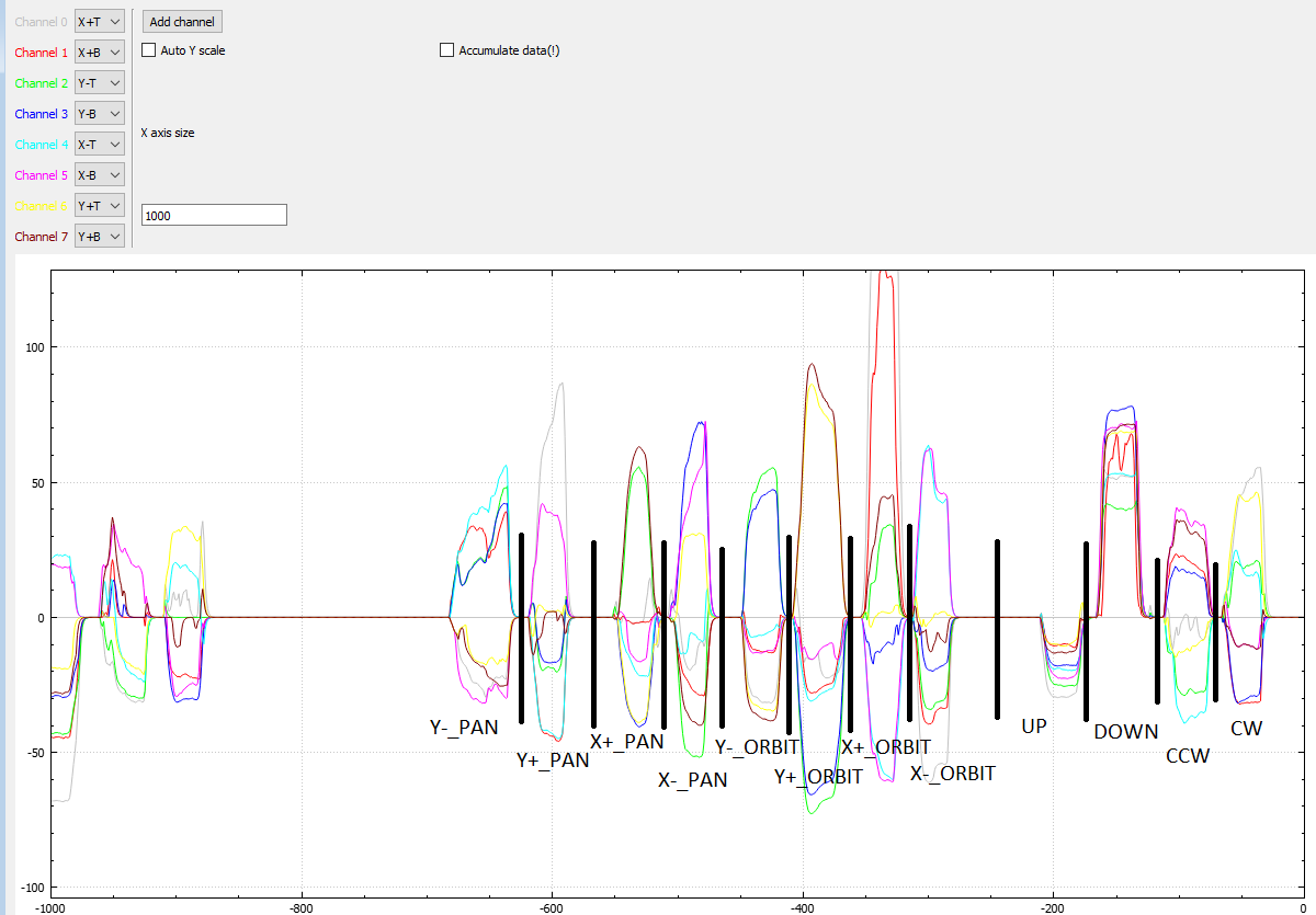
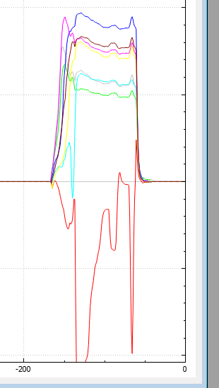
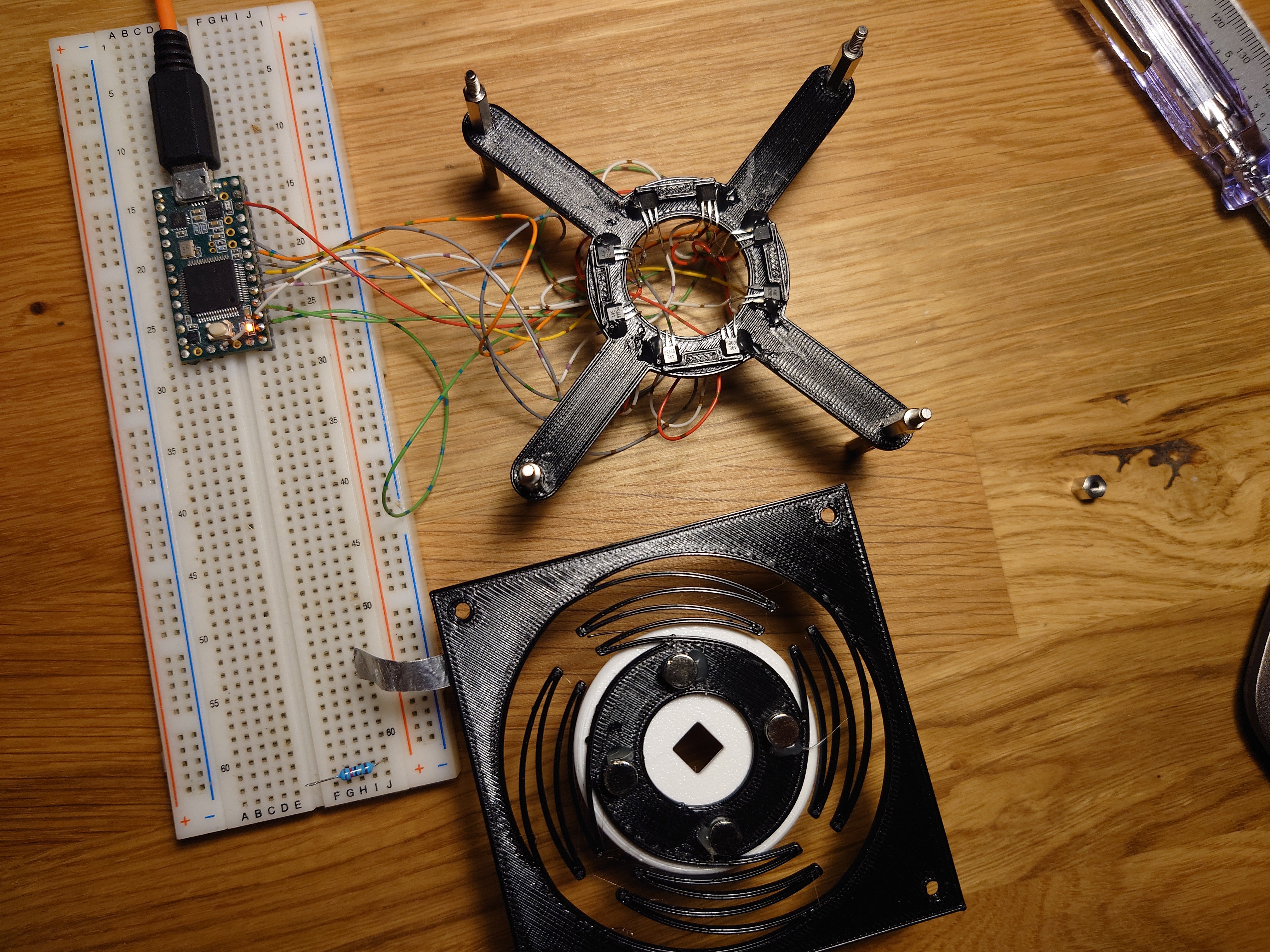
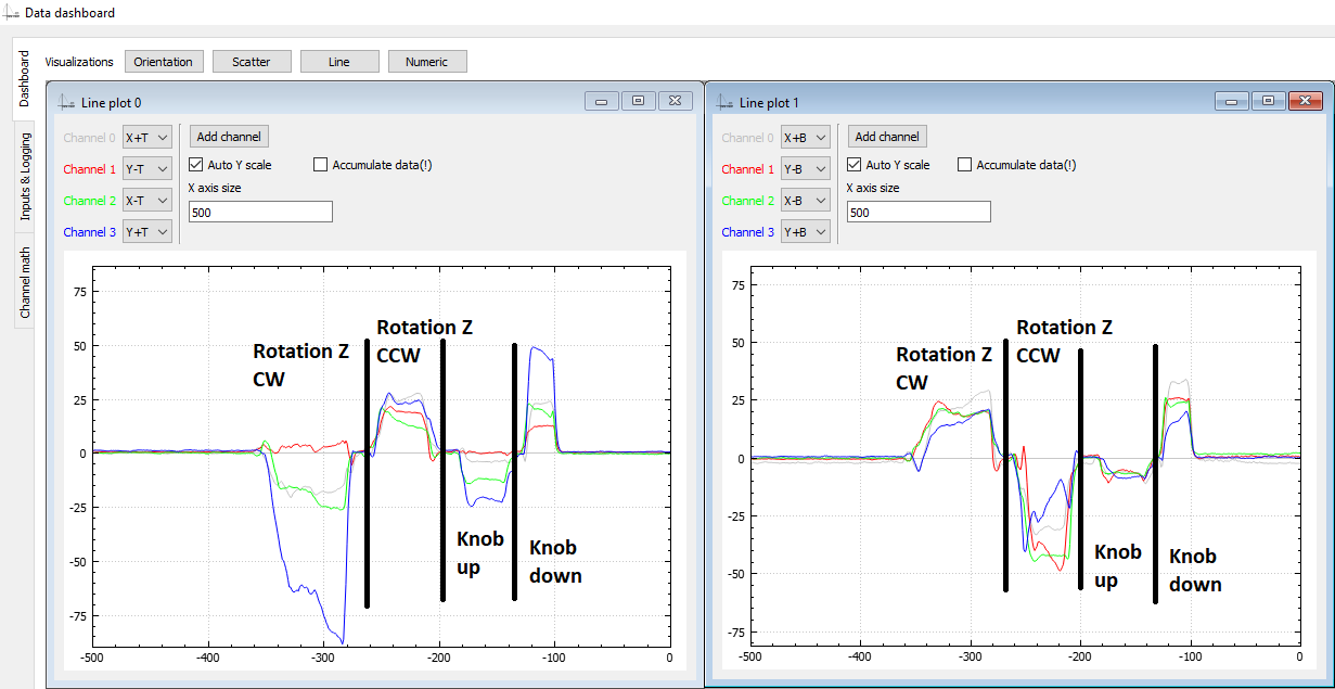
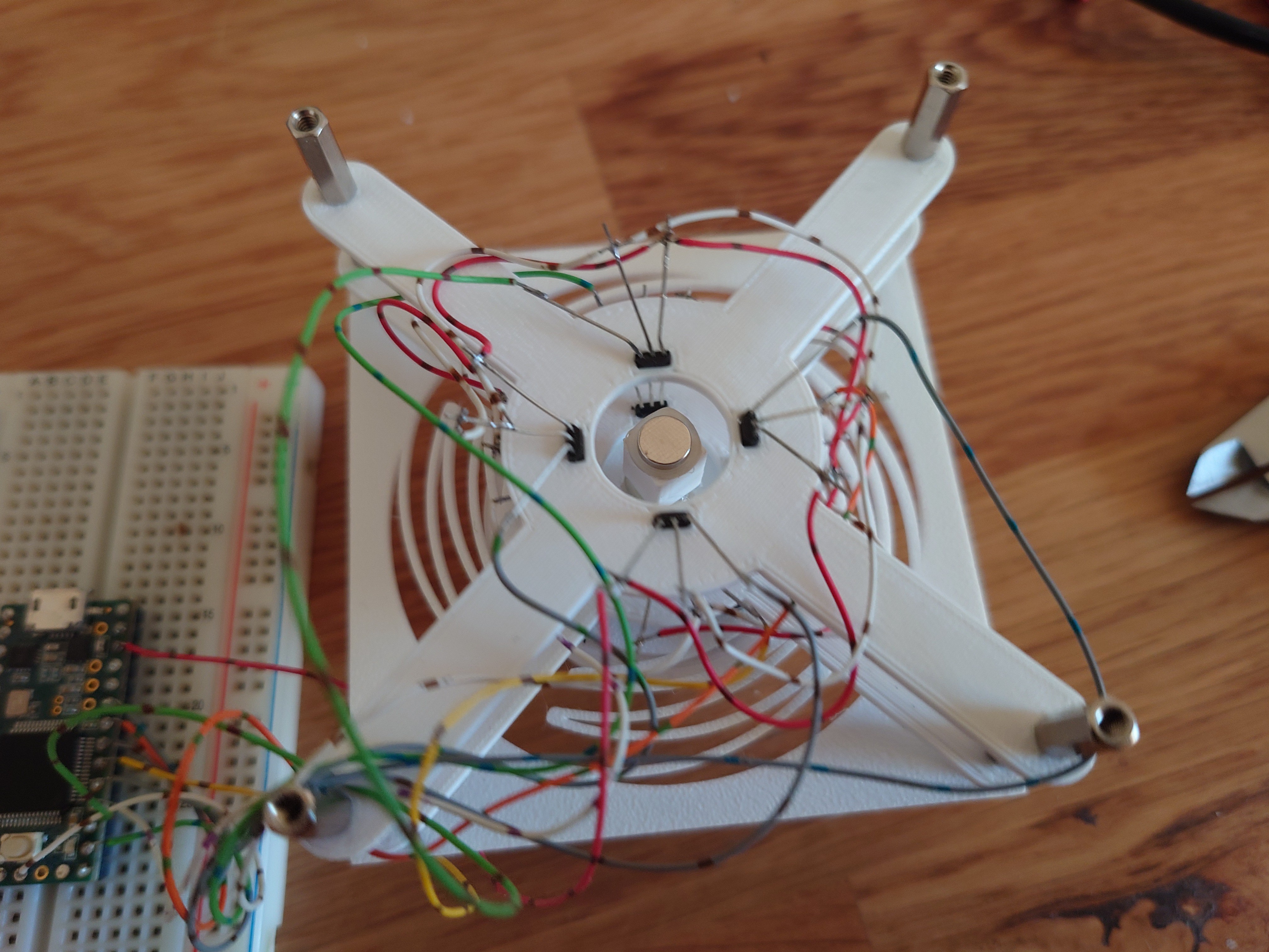
• ESP32-S3 port and electronics

    Vedran10/24/2025 at 18:16 0 comments

    My first choice of MCU is ESP32-S3. It offers a good amount of flexibility and covers all the requirements I want for this project:

    • (Must have) minimum 8 ADC input. Performance of ADC is slightly poorer comparing to Teensy 3.2 and the final decision hangs on the test to ensure that data is sufficient to run the algorithm developed on Teensy
    • (Must have) I2C bus to drive a screen, used to configure the mouse settings
    • (Must have) Few free output pins to drive few FETs, and addressable LEDs, this thing needs some bling
    • (Must have) At least 6 free input pins used to connect the buttons. Since this is a mouse targeting CAD usage, having some buttons to emulate keyboard keys is a must (e.g. ESC, Enter, ...)
    • (Must to have) One of:
      • USB that supports HID device, emulating keyboard & mouse
      • BLE that supports HID device, emulating keyboard & mouse   <--- Preferably BLE, it would be cool to make this a wireless mouse

    With this in mind, the priority is to validate the feasibility of ESP32-S3, although I don't have any big concerns at the moment, it looks to live up to spec above.

    On the side, I've also been playing with drafting some design ideas, trying my hand at designing something nice. It's probably the first time I'm trying to make something somewhat "visually appealing", and not just a square box 😂

    The funky looking "spoiler" on top is meant to house around 5 programmable buttons, and the hole on top of the knob will likely have 2 buttons as well. Cutout in front is where the screen sits.

    Electronics

    On the electronics side, I'm hoping to get the device to be wireless, which the requires a battery and a charger. Old phone battery I have lying around should provide enough juice for a couple of hours of continuous runtime, and paired with something like TP4056, it can get charged while the device is plugged in.

  • Software/MCU consideration

    Vedran10/14/2025 at 19:19 0 comments

    With the concept confirmed, it's time to look into the software side of the project. When it comes to connecting 3D mouse to the computer and letting it interact with e.g. CAD software, there's generally 2 approaches in DIY projects. One approach is to simply emulate a mouse and a keyboard, then convert 3D mouse movements into the keyboard shortcuts combined with mouse movements. Other option is to use 3D Connexion driver and tweak your mouse to be recognized as a 3D Connexion device. 

    Mouse/Keyboard approach


    I've been testing so far the mouse/keyboard approach, and while it is pretty decent, it comes with some annoyances. Biggest one for me is that you're essentially controlling a mouse pointer, which is bound by the screen size - it cannot be moved more than the screen edges. Furthermore, when the motion is completed, mouse pointer has to be retracted back to where it started. At least I'd like that, in order to not have to jump to a regular mouse to reposition the pointer.

    Mouse acceleration


    I tackled this in one of my tests, by simply counting the displacement and then moving the cursor back by the same displacement. For example, which orbiting a part, mouse pointer perhaps moved +60 points in X direction and +5 in Y direction, so when orbiting stops, moving the cursor by -60, -5 should get it back to where it started. While this probably works fine on linux & mac, turns out windows has on-by-default feature called "Enhance pointer precision" that completely messes this up.

    "Enhance pointer precision" takes into account pointer acceleration when moving around the screen. So now, to properly retract the pointer back to where it started, it's not enough to track how much it moved, but also how fast it was accelerating. If a pointer moved by +60, -5 over 5 second, and we try to retract that in a single mouse movement, we will blow past original mouse position due to mismatched acceleration. Instead, it's necessary to match to original acceleration during retraction. With that in mind, retract algorithm gets fairly complex and inconsistent when accounting for all possible movement. Simple option would be to just disable mouse "Enhance pointer precision" in Windows.
    Another smaller limitation is that emulating a mouse/keyboard relies on using in-app shortcuts. These shortcuts can differ from app to app, requiring more work to create a solution that works with multiple programs.

    3D Connexion driver approach


    Another way to interface 3D mouse with the PC is via 3D Connexion driver. Basically, someone (my search leads me here https://github.com/AndunHH/spacemouse ) has spent time reverse-engineering communication protocol 3Dconnexion uses to interact with their 3D mice. Using this information, it is possible to emulate a USB device that follows the same protocol. In other words, a DIY space mouse can be recognized as a legit 3D Connexion device and leverage their proprietary driver for interaction with supported CAD software.

    From what I could see online, this approach solves both of my annoyances with keyboard/mouse approach but it comes at a cost of relying on proprietary software, outside of my control. Basically, things could stop working at any point for any reason. 

    There's also an ethical question that rarely comes to my mind when working on DIY projects, but here somehow it inadvertently seems to poke me every time I consider this option. Despite seeming to be a superior approach, it somehow doesn't feel right to base my solution on it. 

    Summary

    Choice of the approach here mandates hardware required to go forward with this project. I have written the test code so far to run on Teensy 3, using arduino framework. However, teensy currently doesn't support implementing custom USB descriptors needed to test 3D Connexion solution. So this would prompt a different MCU. 

    Taking into account that I likely want to take this project wireless as...

    Read more »

  • Technology test 3: Final concept

    Vedran09/24/2025 at 18:03 0 comments

    This project has been shelved for the last year, but I'm finally back and determined more than ever to conclude this project! Building on the last few technology test, I'm pretty determined on keeping the hall sensors, despite all the good suggestion I received in texts and comments that I should instead go for a 3D magnetometer. I might investigate that option later, but for now I'd prefer to use whatever I have around :) I also looked into other variants that are not based on magnetism, like inertial (based on IMU), but have quickly abandoned that road. It seems quite impractical to move your pointer just because you decided to reposition the mouse on your desk :D

    Anyway, the final concept is based on 4 pairs of hall-effect sensors, placed 90 deg apart with a magnet hovering on the knob above each pair. Essentially, what was done in technology test 2. However, I chose to experiment a bit with the spacing of the sensors in a pair, and height of the magnet from them. I cam to the conclusion that sensors have to be spaced fairly close as the mouse movement is only +/- 1cm and a few degrees of tilt. So I went from initial 8mm, down to 4mm and finally at 1mm.

    This has produced very clear data for each of the 12 gestures that the mouse needs to support:

    While testing, I also got some insights for the next phase. Namely, the knob must be attached to the flexture as close to the sensors as possible (while still having the space to move). In other words, the knob can't be suspended on it's top surface. Also, the knob must have movement limits, especially in the -Z direction (push action) otherwise the hall effect sensors starts acting out.

    I'm assuming this has to do something with the sensing area inside the sensor itself, and its alignment with the magnetic field. That alignment might be very sensitive at such close proximity. But keeping the magnet 5-7mm away from the sensor helps avoid that.

    On the software side of things, one important part is normalizing sensor values. Something as simple as subtracting average of all sensor values from each value before using it for computation helps avoid wrong readings due to e.g. accidentally pressing on the knob while trying to pan, or pulling the knob while orbiting. 

  • Quick practical test

    Vedran06/29/2024 at 22:05 0 comments

    After the last success, I had to give it a quick go in actual CAD software. So I went to steer my test code from previous examples into something that can roughly detect which of the gestures mouse is currently doing, and inject the right command into Fusion 360 to be able to zoom, pan and orbit an object.

    I made a simple algorithm that represents each gesture with a sum of all sensors values comprising that gesture. For example, from previous post:

    The following gestures would be represented by the following sums(translate=pan):

        _sums[XP_PAN] = sensor(XpT) + sensor(XpB) + sensor(YmB) + sensor(YpT) + sensor(XmB) + sensor(XmT) - sensor(YmT) - sensor(YpB);
        _sums[XP_ORBIT] = sensor(XpT) + sensor(XpB) - sensor(YmB) - sensor(YpT) - sensor(XmB) - sensor(XmT) - sensor(YmT) - sensor(YpB);
    
        _sums[XN_PAN] = sensor(XpT) + sensor(XpB) + sensor(YpB) + sensor(YmT) + sensor(XmB) + sensor(XmT) - sensor(YpT) - sensor(YmB);
        _sums[XN_ORBIT] = sensor(XmB) + sensor(XmT) - sensor(YmB) - sensor(YpT) - sensor(XpT) - sensor(XpB) - sensor(YmT) - sensor(YpB);
    

    XpT represents a sensor input X+, top and XpB sensor X+, bottom, as my design features 2 sensors on each axis. The algorithm then goes on to compare all sums to find the largest one, and takes that as the most likely gesture. The exact gesture is actually not very important, as long as we can reliably determine in which of the following states we are: idle, pan, orbit, zoom (zoom is represented by lifting and pressing on the knob; +/-Z axis translation)


    Once we know the gesture, we need to somehow extract X/Y motion magnitudes to move mouse, and I should've spent more time on that as the current example doesn't do a very good job with tracking when in panning mode. But overall, I got what I needed and I could somewhat do what I wanted with the part.

    Generally, approach seems to work nice. Orbiting work as I would expect it, but panning can be a bit difficult, and that's mostly because I didn't yet look into what data gives the best tracking when in panning mode. Also, zoom is going to need reworking. Even though the current zoom speed is the slowest possible (on tick per refresh rate, at 100Hz that's still pretty fast). I am thinking that zoom will be somehow incremented internally at a much lower rate so that is ticks to one every 100 - 500 ms.

    Currently, though, my biggest annoyance is that the test setup needs to be held with one arm as it's too light and would otherwise just move around.

  • Technology test 2​

    Vedran06/27/2024 at 19:04 0 comments

    Another arrangement was inspired by an existing 3D mouse project, where the sensors lie flat on the board and magnets hover above them. Ignoring the fact the the linked project uses completely different technology, and doesn't use magnets at all, the design itself should in theory allow for tracking all 6 degrees of freedom. I went with 4 sensing areas, each area containing a magnet and 2 sensors.

    I feel like using 4 magnets results in simpler math behind tracking, and makes tracking more precise. First look at the data looks promising, and I feel that hall effect sensors are placed too fat apart from eachother. Also the feedback on lifting the knob looks too weak, but is detectable.

    Overall, the result looks promising and I'll iterate on this for a while.

    Software

    Softwarewise, I'm hoping to get away with a simple algorithm that tracks the 8 input signals, takes them through a low pass filter, normalizes them, sums them into 'signals of interest' and looks at the currently dominant signal. 'Signal of interest' would be sums of signals we know compose a 'movement of interest'. For example, looking at the picture above, Translate +X movement would be represented by a sum of all input signals above 0 plus negated signals below 0; i.e. (translate_+x)=(Y+T)-(X+T)-(X-T)-(Y+T)+(X+B)+...

    The movement of the mouse itself will likely just be a sum of data in X direction for X movement, and Y direction for Y movement and the software only need to know whether we're orbiting or panning to know which key combination to inject on the side of the mouse movement to work with the desired CAD software. Except that for tracking X axis movement, Y axis sensors would give us the most reliable and vice versa, so sum of X is likely movement in Y and sum of Y is movement in X direction. :D

  • Technology test 1

    Vedran06/26/2024 at 19:25 0 comments

    I am fairly certain I'd like to tackle this with some magnets, and as many OH49E hall effect sensors as necessary. I've chosen to use 3D printed flexture to hold the mouse itself, suspend a magnet on it, and track it with hall effect sensors. Teensy 3 acting as an HID device then reads the sensors and commands the mouse movement.


    First arrangement contained one long magnet placed in the middle of 8 hall effect sensors, split in 2 rows.

    Idea was that by tilting the magnet 45 deg between the sensors, it would be easier to track rotation. And while that turned out to be true, the rest of the tracking wasn't really something that made a lot of sense.

    For a second attempt, I tried to reuse this contraption with a different magnet configuration. Instead of one long, oddly polarized magnet, use two round magnets with poles on their flat sides. Magnets are spaced out so that they are slightly higher than the two sensor plates.

    And that approach indeed produced relatively nice output:

    Problem, however, was that tracking rotation around Z axis became impossible due to it causing no change in poles facing the sensors. The graph below shows twisting of the knob back and forth, for the whole duration of the graph. The readings here are simply the readings of how much the knob was accidentally pressed or pulled during the motion.

     Subtracting average of the data produced nothing interesting. Some of the higher spikes are also a bit misleading, but they are a product of the thin magnet being pushed passed a sensor, causing S pole, then N pole to move past the sensor and changing the value from positive to negative (and vice versa).

    So if this to be a truly 6DOF mouse, a different approach is needed.