-
Quick practical test
06/29/2024 at 22:05 • 0 commentsAfter the last success, I had to give it a quick go in actual CAD software. So I went to steer my test code from previous examples into something that can roughly detect which of the gestures mouse is currently doing, and inject the right command into Fusion 360 to be able to zoom, pan and orbit an object.
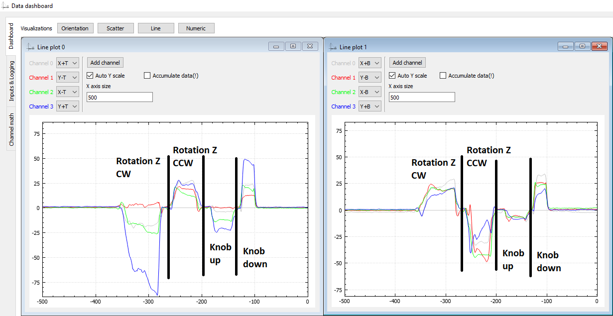
I made a simple algorithm that represents each gesture with a sum of all sensors values comprising that gesture. For example, from previous post:
The following gestures would be represented by the following sums(translate=pan):
    _sums[XP_PAN] = sensor(XpT) + sensor(XpB) + sensor(YmB) + sensor(YpT) + sensor(XmB) + sensor(XmT) - sensor(YmT) - sensor(YpB);
    _sums[XP_ORBIT] = sensor(XpT) + sensor(XpB) - sensor(YmB) - sensor(YpT) - sensor(XmB) - sensor(XmT) - sensor(YmT) - sensor(YpB);

    _sums[XN_PAN] = sensor(XpT) + sensor(XpB) + sensor(YpB) + sensor(YmT) + sensor(XmB) + sensor(XmT) - sensor(YpT) - sensor(YmB);
    _sums[XN_ORBIT] = sensor(XmB) + sensor(XmT) - sensor(YmB) - sensor(YpT) - sensor(XpT) - sensor(XpB) - sensor(YmT) - sensor(YpB);
XpT represents a sensor input X+, top and XpB sensor X+, bottom, as my design features 2 sensors on each axis. The algorithm then goes on to compare all sums to find the largest one, and takes that as the most likely gesture. The exact gesture is actually not very important, as long as we can reliably determine in which of the following states we are: idle, pan, orbit, zoom (zoom is represented by lifting and pressing on the knob; +/-Z axis translation)
Once we know the gesture, we need to somehow extract X/Y motion magnitudes to move mouse, and I should've spent more time on that as the current example doesn't do a very good job with tracking when in panning mode. But overall, I got what I needed and I could somewhat do what I wanted with the part.Generally, approach seems to work nice. Orbiting work as I would expect it, but panning can be a bit difficult, and that's mostly because I didn't yet look into what data gives the best tracking when in panning mode. Also, zoom is going to need reworking. Even though the current zoom speed is the slowest possible (on tick per refresh rate, at 100Hz that's still pretty fast). I am thinking that zoom will be somehow incremented internally at a much lower rate so that is ticks to one every 100 - 500 ms.
Currently, though, my biggest annoyance is that the test setup needs to be held with one arm as it's too light and would otherwise just move around.
-
Technology test 2
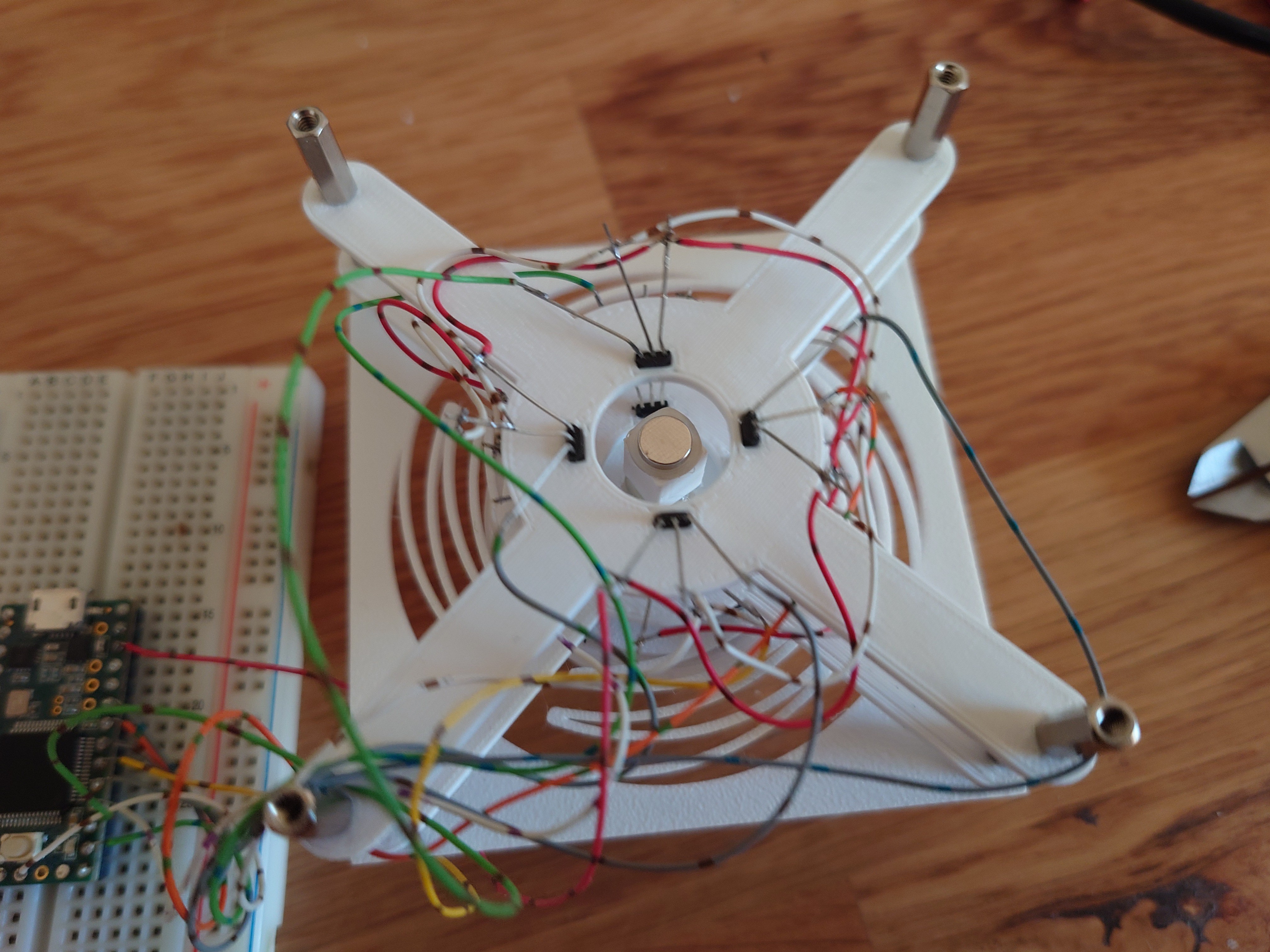
06/27/2024 at 19:04 • 0 commentsAnother arrangement was inspired by an existing 3D mouse project, where the sensors lie flat on the board and magnets hover above them. Ignoring the fact the the linked project uses completely different technology, and doesn't use magnets at all, the design itself should in theory allow for tracking all 6 degrees of freedom. I went with 4 sensing areas, each area containing a magnet and 2 sensors.
I feel like using 4 magnets results in simpler math behind tracking, and makes tracking more precise. First look at the data looks promising, and I feel that hall effect sensors are placed too fat apart from eachother. Also the feedback on lifting the knob looks too weak, but is detectable.
Overall, the result looks promising and I'll iterate on this for a while.
Software
Softwarewise, I'm hoping to get away with a simple algorithm that tracks the 8 input signals, takes them through a low pass filter, normalizes them, sums them into 'signals of interest' and looks at the currently dominant signal. 'Signal of interest' would be sums of signals we know compose a 'movement of interest'. For example, looking at the picture above, Translate +X movement would be represented by a sum of all input signals above 0 plus negated signals below 0; i.e. (translate_+x)=(Y+T)-(X+T)-(X-T)-(Y+T)+(X+B)+...
The movement of the mouse itself will likely just be a sum of data in X direction for X movement, and Y direction for Y movement and the software only need to know whether we're orbiting or panning to know which key combination to inject on the side of the mouse movement to work with the desired CAD software. Except that for tracking X axis movement, Y axis sensors would give us the most reliable and vice versa, so sum of X is likely movement in Y and sum of Y is movement in X direction. :D
-
Technology test 1
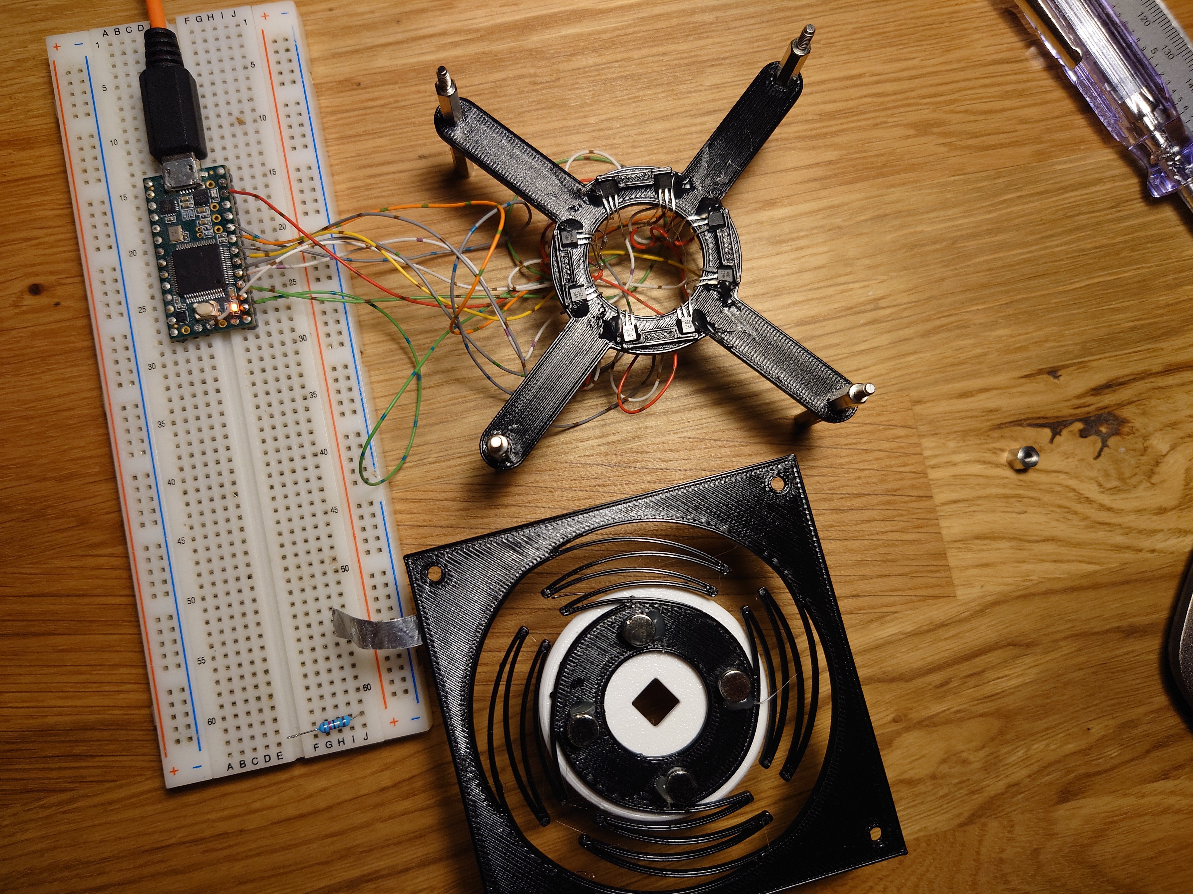
06/26/2024 at 19:25 • 0 commentsI am fairly certain I'd like to tackle this with some magnets, and as many OH49E hall effect sensors as necessary. I've chosen to use 3D printed flexture to hold the mouse itself, suspend a magnet on it, and track it with hall effect sensors. Teensy 3 acting as an HID device then reads the sensors and commands the mouse movement.
First arrangement contained one long magnet placed in the middle of 8 hall effect sensors, split in 2 rows.Idea was that by tilting the magnet 45 deg between the sensors, it would be easier to track rotation. And while that turned out to be true, the rest of the tracking wasn't really something that made a lot of sense.
For a second attempt, I tried to reuse this contraption with a different magnet configuration. Instead of one long, oddly polarized magnet, use two round magnets with poles on their flat sides. Magnets are spaced out so that they are slightly higher than the two sensor plates.
And that approach indeed produced relatively nice output:
Problem, however, was that tracking rotation around Z axis became impossible due to it causing no change in poles facing the sensors. The graph below shows twisting of the knob back and forth, for the whole duration of the graph. The readings here are simply the readings of how much the knob was accidentally pressed or pulled during the motion.
Subtracting average of the data produced nothing interesting. Some of the higher spikes are also a bit misleading, but they are a product of the thin magnet being pushed passed a sensor, causing S pole, then N pole to move past the sensor and changing the value from positive to negative (and vice versa).
So if this to be a truly 6DOF mouse, a different approach is needed.
 Vedran


