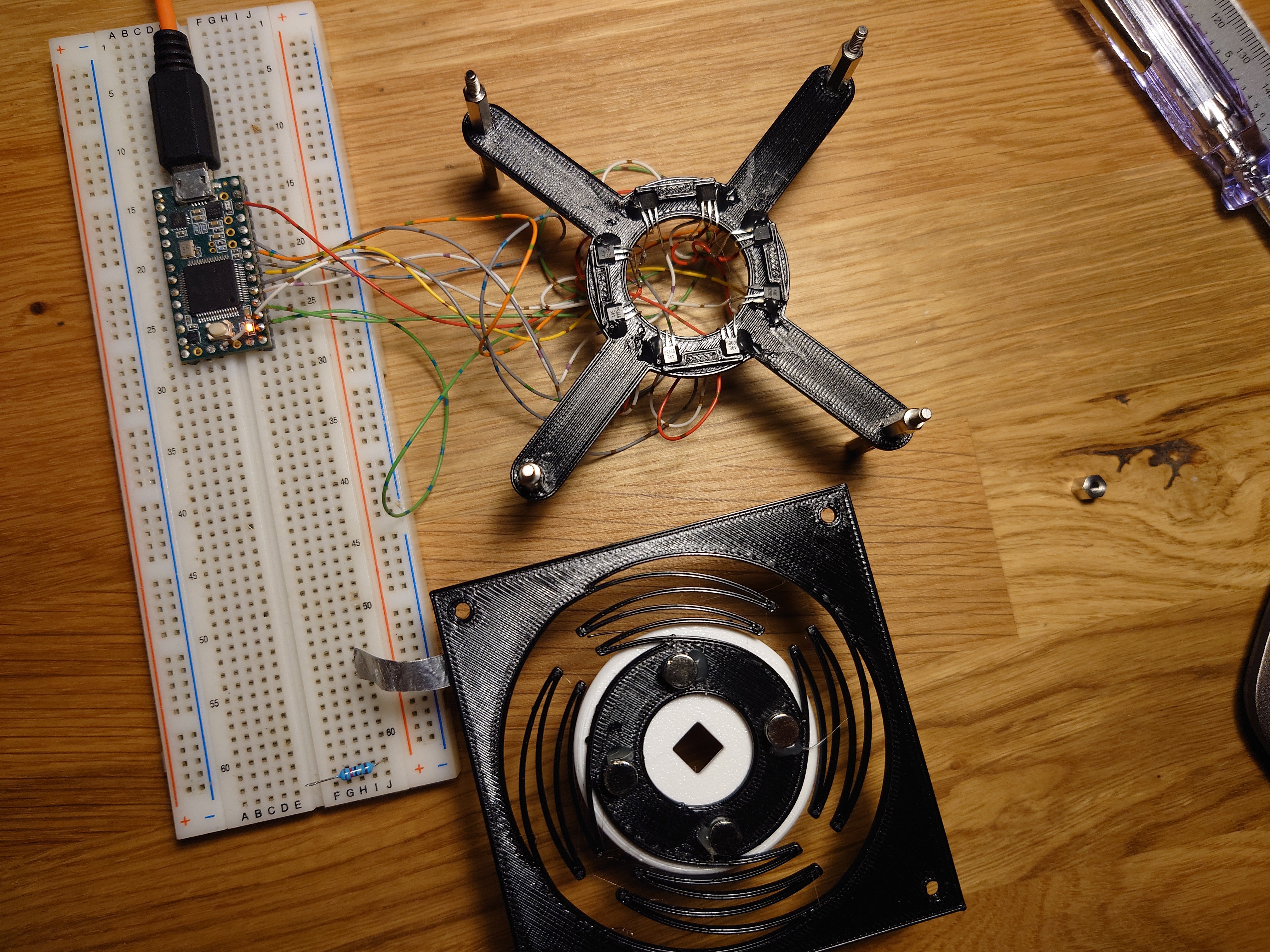
Another arrangement was inspired by an existing 3D mouse project, where the sensors lie flat on the board and magnets hover above them. Ignoring the fact the the linked project uses completely different technology, and doesn't use magnets at all, the design itself should in theory allow for tracking all 6 degrees of freedom. I went with 4 sensing areas, each area containing a magnet and 2 sensors.


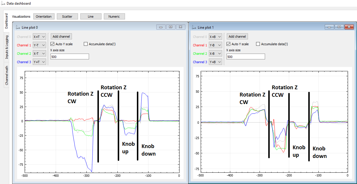
I feel like using 4 magnets results in simpler math behind tracking, and makes tracking more precise. First look at the data looks promising, and I feel that hall effect sensors are placed too fat apart from eachother. Also the feedback on lifting the knob looks too weak, but is detectable.


Overall, the result looks promising and I'll iterate on this for a while.
Software
Softwarewise, I'm hoping to get away with a simple algorithm that tracks the 8 input signals, takes them through a low pass filter, normalizes them, sums them into 'signals of interest' and looks at the currently dominant signal. 'Signal of interest' would be sums of signals we know compose a 'movement of interest'. For example, looking at the picture above, Translate +X movement would be represented by a sum of all input signals above 0 plus negated signals below 0; i.e. (translate_+x)=(Y+T)-(X+T)-(X-T)-(Y+T)+(X+B)+...
The movement of the mouse itself will likely just be a sum of data in X direction for X movement, and Y direction for Y movement and the software only need to know whether we're orbiting or panning to know which key combination to inject on the side of the mouse movement to work with the desired CAD software. Except that for tracking X axis movement, Y axis sensors would give us the most reliable and vice versa, so sum of X is likely movement in Y and sum of Y is movement in X direction. :D
 Vedran
Discussions
Become a Hackaday.io Member
Create an account to leave a comment. Already have an account? Log In.